Vacuum brake booster
- Vacuum booster and interchangeability of brake parts
- Vacuum booster from BMW
- Installing a vacuum booster
- Vacuum booster from GAZ-2401
- Diagram, design and principle of operation of the brake system of UAZ vehicles
Other questions about the brake system
- How to get rid of squeaking brake pads?
- How to overcome a large coefficient of unevenness of braking forces?
- Brakes from Volga (self-supplying cylinders)
- What to look for when buying a brake cylinder
- What to do to prevent RTC from turning sour
- The brake pedal is falling...
- Disc brakes on UAZ classic?
- How to set the emergency brake pressure warning light?
- Emergency pressure alarm from Zhiguli
- What is the best brake fluid to use?
- Hydraulic brake condition indicator (article)
- Which brake pads are best? Riveted or glued
- How to remove a brake drum
- Tips for adjusting brakes
- Low-mounted brakes - increased pedal travel
- Procedure for bleeding the hydraulic system
- Installation of disc brakes on geared military axles
- Installing disc brakes on “loaf” collective farm bridges
After checking the brake system, I bought a UAZ. And I don’t regret it!
How to get rid of squeaking brake pads?
The squeaking of brakes on a UAZ is its integral attribute. You may get the impression that the pads were worn down to the rivets, but this is usually not the case and the squeaking occurs due to dirt on the pads and brake drum. Intensive braking (but not skidding) from high speed helps a little. As a rule, the remainder goes through without a squeak. Personally, I’m not worried about this, quite the contrary. This squeak works better than a beep, especially if someone is cutting off.
My whistle disappeared after replacing all the cylinders with self-propelling ones from Volga. From which I can assume that the nature of this phenomenon lies in the uneven distribution of the load on the pads when using standard cylinders. No matter how you adjust them, after several brakings the gaps become different.
I once read in ZR a long time ago, like advice from experienced people, you need to drill two or three holes in the brake lining the thickness of a pencil lead and insert these same rods there, and so it was stated that all squeaks are due to the properties of graphite.
Replacing front pads on a UAZ
Before starting replacement work, to comply with safety regulations, put the car on the handbrake and place chocks under the wheels. Further:
- loosen the nuts, jack up the car and unscrew the nuts completely and remove the wheel;
- turning the adjusting eccentric with a key of 17, bring the pads together;
- unscrew and remove the drum;
- remove the pressure springs with cups;
- remove the tension spring;
- Using a 19mm wrench, unscrew the support pin nuts and remove them.
Replacing the front pads of a UAZ
This completes the disassembly, but before replacing, do several operations:
- Check the integrity of the protective caps.
- Place a little grease under the protective cap; this will prevent rust from forming inside the cylinder.
- Grind down the bead on the drum. Check the inner diameter of the drum, its maximum value is 281 mm.
Assembly proceeds in reverse order, but there are several nuances:
- Not everyone has special pliers to install the tension spring. I do it this way: I make a ring with a piece of wire and hook it onto the spring. I pull it out and use pliers to guide it into the seat.
- The support bolt marks work for new pads and drum. In practice, after replacement, you will have to adjust.
- Do not install the wheel until the pad clearances have been adjusted.
After replacement, press the pedal 2-3 times to return the brakes to working condition. Periodically, to maintain the gap between the pads and the drum, it must be adjusted manually.
How to overcome a large coefficient of unevenness of braking forces?
- Mark and remove ALL brake drums and use a caliper to measure their diameter. As a result of uneven wear or grooves, this size can vary within quite large limits - hence the unevenness. Check if the brake fluid or transmission is leaking somewhere. If it leaks, fix it.
- Make two pairs of them - for the front and rear axles - with the same (within 0.2-0.3 mm) diameter.
- Mark and remove the pads. Wash and clean them and all parts of their suspension.
- Assemble so that the pads work “on their own” drums. Adjust carefully.
- Ride around the city for a day.
Symptoms of a problem
You can determine that the pads need to be replaced without removing the wheels based on several signs:
- when braking, the car pulls to the left or right;
- unpleasant sound of metal rubbing against metal;
- creaking when braking;
- The drum and wheel rim get hot.
Depending on which side the pads are better on, the car pulls in that direction when braking.
Friction against metal is, of course, an extremely bad situation. Pads or linings must be changed when they are worn out, when the rivets are recessed into the lining by less than 0.5 mm and the friction material is damaged.
When the drum with the wheel disc heats up significantly, this may also be due to a faulty pad. For example, the tension spring burst, the lining came off and jammed, but more often it is due to other reasons. An article about such heating is here.
To monitor brake wear, there are holes in the shield.
Front brake pad arrangement
Vacuum booster and interchangeability of UAZ brake parts
Since November 1988, a vacuum brake booster (VUT) has been installed on UAZ vehicles, reinforced shields and pads have been introduced (reinforced pads have three extrusions at the edges on each side), and the diameters of the rear brake wheel cylinders (RTC) have been changed. On vehicles without a vacuum booster
The diameters of the front RTCs are 32 mm, the rear ones are 32 mm.
On cars with a vacuum booster,
the diameters of the front RTCs are 32 mm, the rear ones are 25 mm. Wheel brake cylinders with a piston diameter of 32 mm are marked “32” on the outer surface, and those with a piston diameter of 25 mm are marked “25”. On vehicles without VUT, it is allowed to install front reinforced pads, brake mechanisms, and axles with reinforced brake mechanisms. Rear reinforced parts cannot be installed on vehicles without VUT. Only reinforced parts are installed on vehicles with VUT.
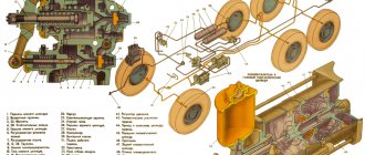
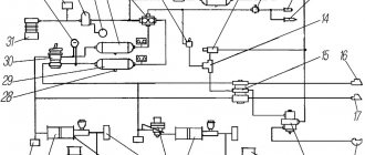
Detailed diagram of the UAZ “Bukhanka” braking system
In the diagram, numbers represent the various components.
1) Brake disc; 2) Front wheel brake caliper; 3) Front contour; 4) Master brake cylinder; 5) Reservoir with brake fluid movement sensor; 6) Vacuum booster; 7) Pusher; Brake pedal; 9) Brake light switch; 10.22) Brake pads; 11) Rear brake cylinder; 12) Back contour; 13) Rear axle housing; 14) Load spring; 15) Pressure regulator; 16) Rear cable; 17) Equalizer; 18 Central cable; 19) Parking brake lever; 20) Brake fluid emergency level indicator; 21) Parking brake warning switch.
The braking system of the UAZ “Bukhanka” has its most common breakdowns. For example: increased braking distance, sinking brake pedal, creaking and noise when braking, leaking brake fluid.
The causes of all these problems are also known. This, as a rule, is a violation of the tightness of the system, low level of brake fluid, wear of the pads and untimely replacement of consumables.
In most cases, if the problems are not related to wear of parts, simply bleeding the braking system will help. It is performed during any depressurization of circuits, during renewal of brake fluid, as well as during any replacement of system parts (pipes, hoses, cylinders).
Do not forget that for pumping you will most likely need an assistant.
Installing a vacuum brake booster
Please note that: The use of a vacuum booster increases the twist of the front springs and their load. Therefore, the plant previously changed the suspension kinematics of the front springs (on old cars the shackle is in the front; on new cars it’s in the rear; the change was introduced in the first quarter of 1988). At the same time, due to a change in the swing kinematics of the front axle, it was necessary to replace the front driveshaft of the 469B model with another one - model 3151, 9 mm shorter. Therefore, having installed a vacuum booster on an old car without altering the front suspension, it is necessary to constantly monitor its condition and the behavior of the car. “A vacuum will help you slow down” and additions to this article.
Vacuum booster from GAZ-2401
The trick is that the VUT GAZ-2401 comes as a separate unit (not near the pedals), and I have lower pedals and therefore don’t want to redo the pedal assembly.
There are no problems with the installation. From Ch. brake from the cylinder there is a tube to the amplifier, from the amplifier there is a tube to the circuit separator, and from the latter there are two tubes - one to the front wheels, the other to the rear. Vacuum from the intake manifold. There is also a circuit indicator (optional) - see doc. according to GAZ-24. Doubts arise about the fair passage of technical inspection. And it seems that it is rather weak for an UAZ, but still better than without it.
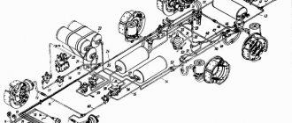
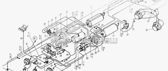
Description of the hydraulic brake drive circuit:
- master brake cylinder;
- hazard warning light;
- a hose with a diameter of 12 x 26, connected to the engine intake manifold;
- hydraulic vacuum booster (24-3550010);
- brake separator (24-3575010);
- hydraulic vacuum booster bleeder fitting;
- control lamp;
- rear wheel brake cylinders;
- front wheel brake cylinders;
- air filter for hydraulic vacuum booster.
Bleeding the brake system with an installed hydraulic-vacuum brake booster GAZ-24. Fill the main brake cylinder with BSK or Rosa liquid (Do not pour Neva, it is not compatible with GAZ-24 brakes, it is also not allowed to mix BSK and Rosa), turning the valve in the separator 2-2.5 turns brakes, pump the brakes of the rear and front wheels alternately, then the hydraulic vacuum booster. We close the separator bleeder valve with the brake pedal released. As always, when doing this work, add fluid to the brake master cylinder so that no air gets into the system. If all brakes and their actuators are adjusted correctly and there is no air in the system, the brake pedal should not go down more than half of its travel when you press it with your foot, and the hazard warning lamp should not light up when the ignition is on.
Vacuum booster from BMW to UAZ
I installed a vacuum brake booster from a 1990 BMW-7 (inflated). The only thing that is needed in advance is for a turner to grind out the adapters (since the UAZ brake pipe fittings differ in size and thread from the holes on the BMW-7 master brake cylinder). I also removed the reinforcing plate on the engine side panel and replaced the working self-regulating brake cylinders with GAZ-24 ones (they fit without modifications). The brakes have become much softer and more effective. The amplifier has been working for four years, during which time I haven’t even climbed or taken it apart.
I heard that Volga brakes are suitable for UAZ. How are they better or worse than their relatives?
Volga brake cylinders, starting from 24 (since 1970), are all self-feeding; manual adjustment of the pads is not required and less effort is required when braking. Back
UAZs are suitable from 24 (by 32 mm), because on 2410, 31029, ... (I mean the rear cylinders) there is a different thread for the brake pipe (without an intermediate bolt).
On the front
- from 2410 or 24 (the first are better - they have foam inserts, which must be lightly impregnated with BSK or castor oil, which prevents corrosion). Beware of the "leftists" - there are plenty of them in South Port. The main difference is the appearance: the anthers do not “shine”, are irregular in shape, and there is often rust under the anthers. You can also change the pads themselves - the force will decrease somewhat, and most importantly, the mileage will increase. They are glued and work almost until they are completely worn out.
After the modification, the brakes need to be pumped MORE CAREFULLY, because due to the locking ring this process is a little “delayed”.
After much thought and reading the statements of smart people (see CHIF’s note above), I came to the conclusion: The front ones are GAZ-3102, aka GAZ-2410, aka .... (they are all the same) diameter 32. Without alterations. I took it and installed it. The rear ones are GAZ-3102, also known as GAZ-2410, diameter 28. With an adapter fitting. I searched for fittings for a long time. There are no UAZ cars from GTZ 3160. The solution was found unexpectedly while looking at the display case in the storeroom. Adapter fitting 6x5 for rear working brake cylinders Moskvich. From a conversation with the seller I learned that there have been no working brakes from Moscow on the 412 for a long time. Available only on 41st. And they have the same problem - on the 41st x5, and on the 412th x6. 10 rub. issue price. Moskvichevsky adapter into a Volgov cylinder, into it our adapter (6x6 to another thread), and into our adapter a tube. Next, nadot. Wrench x12 twist the fittings. Bleed the brakes with a 10-piece spanner (for Volgov models, the fitting is x10). A set of copper washers for the front cylinders (it’s better not to use old ones), 6 pieces per wheel. Well, remember about the possibility of collapsing the tubes. See also the article about installing Volgov cylinders on the website.
What to look for when buying a brake cylinder
The cylinder must be disassembled before installation. Well, or at least bend the anthers. And now there are a lot of them - they look normal, but are rusty inside. And one more thing - in the store they are not very carefully reloaded. When I was choosing for myself, I didn’t find ONE(!) with a whole anther. I had to buy it separately.
In stores there are different cylinders that suit us: From 3102 - very often under their brand there are native UAZ ones, which are NOT even self-priming at all. From GAZ-24, they are also from 3302 - they stand up without problems, like family. The only negative is that on an empty car the rear reaches before the front - in theory, a regulator is needed, but there are no special problems (I’ve been driving for the 5th year already.) From 3160 and from GAZ 2410 - smaller in diameter than from 24 or 3302, but for docking them with our tube we need an adapter - GTZ fitting from 3160 (standardly these cylinders are for 5 mm tubes.)
I installed all FENOX cylinders. In the store I compared the factory rusty ones with sagging threads and the neat FENOX.
What to do to prevent RTC from turning sour
It is necessary to cut rings with a diameter of the RTC from 10mm foam rubber, saturate them with either castor oil or brake fluid, and place them under the anthers of each RTC.
Such nonsense happened. I was driving and suddenly the brake pedal sank to the floor, all the way. The brakes almost disappeared, although they still worked. I went to a UAZ car service center, where they told me that either the vacuum was broken or the main brake... In general, the story is long, but I have already changed two vacuum boosters (not new, but from working cars) and three working cylinders (two of which are new). But NOTHING WORKS OUT!!! The emergency brake light comes on periodically and the brakes are applied only when the pedal is pressed to the floor. The tube that connects to the vacuum sucks air as it should, I pumped the brakes 7-10 times (!!!). I rearranged everything as a complete set from another UAZ (vacuum unit, main brake, and everything that is connected to it. In general, everything except pipes and pads, of course). Brake fluid does not leak anywhere! Its level is always constant!!! Moreover, after quickly pressing the brake pedal several times (with the engine running), it does not “grab.” And when not working, it “grabs” as it should.
I had about the same thing, the pedal sank, the light blinked, however, the fluid level decreased, but very, very slowly. The problem was in the tubes connecting the upper and lower brake cylinders on the front wheels. Moreover, there were no signs of fluid leakage. It looks like they were cold bent at the factory after screwing one end into the cylinder. When trying to unscrew the tube, it burst at the bend, which was at the rear edge of the fitting, and the fitting on the tube did not rotate (the car was less than six months old, it had not seen salt or winter). In short, replacing BOTH tubes cured this defect (bending the tubes over the gas stove).
Try spreading the pads with eccentrics. On UAZ, unlike cars, the brake wheel cylinders are not self-expanding. Therefore, as the pads wear out, you have to move them manually.
Bleeding brakes UAZ 469
The purpose of carrying out pumping manipulations is to remove the air contained in the internal parts of the braking mechanism. Periodically, once a week, inspect the machine for damage and leaks, paying attention to:
- Presence of mechanical damage to pipes;
- Violation of seals in joints;
- Compliance of the amount of working fluid with the required standard;
- Operation of the foot brake lever.
Braking mechanism UAZ (469, 452):
A sign that it is time to perform pumping manipulations is an increased working stroke of the foot brake lever, as well as detection of dips when pressing the foot brake. In addition, the lubricant is changed after repairs or replacement of components or parts of mechanisms. Regardless of the circumstances, you need to refill DOT-4 brake concentrate and bleed the brakes on UAZ 469 and 452 once every two years.
Disc brakes on UAZ classic?
And at the gas station I saw a UAZ with front disc brakes... it was very clearly visible through the alloy wheels... and the owner said that everything from the Volga fit almost like original, only the discs were sharpened (or ground)... and he also said that the car stopped working When braking, try to change lanes in the next lane.
We installed disc brakes from 3160 on UAZ 31512 of our jeep girls. For installation on civil axles, you need a 3160 steering knuckle housing, calipers (2 pcs), brake discs and brake hoses. 40 mm spacers were installed on the hubs.
They could not install disc brakes on the gear axle. The steering knuckle housing 3160 has different connecting (mounting) dimensions.
Disc brakes have been installed for a long time by Igor Anatolyevich Plakhotin from “Silver Key” tel. 358-6474, only they were imported and cost about 300-350 USD with installation.
To install front disc brakes on 31512, 31514, 31519 (without wheel gears) you must:
- Buy two (right and left) steering knuckles assembled with discs, calipers, pads, hubs from model 3160 (price approximately 3000 rubles/piece autumn 2001)
- Replace the steering knuckles assemblies.
- Buy 2 front brake hoses from model 3160.
- Screw hoses 3160 onto the existing brake hoses and bleed the brakes.
At the same time, old rims will not fit. You need either spacers that increase the track, or alloy wheels, or wheels from 3160 with a bore diameter of 16″. Everyone does this, with their spare parts, in my opinion, at 15 a/k in Vykhino. I don’t know about certification, but it seems that only disc brakes are installed at the factory on 3153.
Caution: Traffic regulations prohibit making changes to the brake system that are not provided by the manufacturer. (you will have to undergo certification).
How to set the emergency brake pressure warning light?
So, after bleeding the brakes, you need to turn off the warning light. During this operation, according to the factory instructions, you need to lie under the car for a long time, trying to catch the moment when the lamp goes out, while your partner presses on the pedals, and the brake fluid is lost, and in general, crawling under the car again is not a good idea. bliss! So, you need to unscrew the brake emergency sensor, then using a thin screwdriver and a magnet (the more powerful the magnet, the better) you need to pull out the small steel ball. As soon as you have completed this operation, with any thin tool (screwdriver, thin long awl, etc.) you need to move that same notorious piston until its cut coincides with the hole for the emergency sensor. Then you put the ball in there, tighten the sensor, and, having assembled all this equipment, press the brake pedal firmly and sharply several times to check everything. If the lamp lights up again, it means there is a problem in one of the circuits! The whole job takes from 5 to 10 minutes maximum, and without loss of brake fluid!
Brake fluid should not drip into the sensor response - it should not be there. When disassembling the signaling device, the pistons can only be pulled out in the direction on which it is located, otherwise the cuffs can be torn. There are no cuffs on sale, although they are the same for us with the Mokvich and, possibly, with the Volga and other cars.
The alarm is disgusting - when it goes off, it blocks one of the circuits with its rod. And it is obviously unknown which one! And this is no longer good.
The easiest way to get rid of this is to bleed the excess brake fluid directly from this sensor by slightly unscrewing the front or rear nut with the brakes depressed and the ignition on (with the engine not running), until the light goes out (it’s better to do this, of course, with two people). Of course, this thing only helps with normally working brakes.
Somehow I measured the volume of the brake pipes and the volume of fluid coming out of the turbocharger in one pump - it turned out that it was necessary to pump a maximum of 5 times in order to comply. The liquid in the tube has completely changed. Well, the air is guaranteed to escape from it. With a reserve I make 10 strokes for the far wheel and 5 for the near one - the brakes are a scrap.
Emergency pressure alarm from Zhiguli to UAZ
Unlike the one proposed by Old Man, it signals problems BEFORE the fluid flows out of the tank. For example, the fluid is slowly poisoning - you will find out about this before the brakes fail.
I did this - I bought a Zhigov tank with a lid, cut off the top of the tank with a thread with a hacksaw (it turned out like a neck with a flange). I cut the flange so that it fit inside our standard lid. In the standard lid I cut a round hole for the neck of the Zhigov tank and inserted it inside. It turned out to be a union nut from our standard cap onto a Zhigov neck with a flange. I thoroughly washed the threads of the tank and the lid and assembled the structure with sealant (in the future, the liquid must be filled through the Zhigov lid). All that remains is to screw the cap with the sensor onto the neck protruding from our tank and connect the sensor itself. There is a similar one on the clutch. (The photo shows a later version, with a converted brake reservoir from Volga).
What is the best brake fluid to use?
Fill it with BSK rather than Dew, because BSK is not hygroscopic, non-toxic, does not corrode the rubber of the cuffs, and accordingly, the cuffs will last 10 times longer! It is a fact! Before replacing with BSK, be sure to thoroughly rinse the brake system with industrial alcohol (not drinking alcohol!!!) to remove dirt and dew residue, which will instantly “kill” all of your newly filled BSK. See also the article “Brake fluids”.
Which brake pads are best? Riveted or glued
Glued brake pads - from Volga. Glued ones - they are afraid of oil, they come off and, “bad” ones, they are afraid of water - you cannot stand in a swamp for more than a day if you are above the axles... Riveted ones can rub the drum very well (if the riveting is on its side, it happened to me, or the block will be erased). Riveted ones, even if they break off, they can slow down. The glued ones come off completely and hello...
It is my deep conviction that riveted ones are better. In theory, glued ones are more durable, but I don’t risk testing them to work on an UAZ. A passenger car with at least front disc brakes is one thing. There the block cools better, and the device does not have to be so heavy to stop. And in a drum it turns out like in an oven. In addition, if they are riveted on the left, they will simply last less and the drum itself will be scratched. But the latter is treatable, and the former is not fatal. And a torn glued lining will do such things inside the drum... This concerns the type of pads. And for quality, you need to go to a trusted store, look at the markings, so that they are not blurry, look at the neatness and uniformity of the rivets. And hope for luck.
Glued ones... peeled off after getting brake fluid. Maybe it’s the material, it’s very hard, it doesn’t press well when gluing it to metal, and the result is too thick a layer of glue. Once the pads fell off after standing for a long time (a year) - corrosion just got there. If you drive around the city every day and without deep puddles, then you can take glued ones. But I rarely drive a UAZ and on gullies. And if you leave the pads wet for a long time, they can fall off. So I took the riveted ones.
How to remove a brake drum
You can use the EXISTING puller on the DRUM. In it, in addition to rep. for studs and countersinked holes for countersunk screws, there are also, it seems, 2 or 3 THREADED holes. M8, which do not have a continuation in the metal of the hub. If you screw M8 bolts into them and tighten them smoothly, the drum should be removed. The same was applied to remove the rear axle shafts. You can also moisten this matter with WD40 or BSK.
By the way, a good “liquid key” product includes, among other things, kerosene and acid. It is an order of magnitude more effective than WD-40, it has been tested.
After removing the wheel, I remove the three countersunk screws. Next, I screw three bolts into the special holes for the M8 until they stop in the hub and begin to tighten them in a circle. If this does not help, or as it happened to me - there are holes, but there are no threads in them, then I take a heavy hammer (preferably a small sledgehammer) and hit it as hard as I can at diametrically opposite points on the outside of the brake drum. It takes a long time to knock, but victory always remains with me.
There is a method that, for 100 pounds, helps to remove brake drums stuck to the hubs (although I personally only used it on classics *). The fact is that on the classics the wheels are fastened with bolts, and on the UAZ - with studs. Those. on the classic, after separation from the hub, the drum will simply stop, and the hub will continue to rotate. On a UAZ, the studs will interfere with this, so here this method is not so effective. 1.Hang the wheel on a jack, unscrew all the bolts securing the drum to the hub. 2. Start the engine, put in third gear and accelerate the suspended wheel to 40-50 km/h according to the speedometer. 3. Depress the clutch and SHARPLY press the brake. The drum is braked by the pads, and the hub, due to the accumulated moment of inertia, rotates relative to the braked drum, breaking off all the rust. If you don't succeed the first time, repeat until you succeed. :))
In my life, I have never used bolts to remove drums, either on a UAZ or on a Volga... In taxi parks where Volgas were parked, the mechanic didn’t even install the three fixing screws on the drum…. And the drum was always removed easily and quickly with a few correct blows of a hammer (not a sledgehammer!). You just need to start hitting not along the inner edge of the drum, that is, towards yourself, but along the outer edge of the drum. That is, the direction of impact should be directly opposite to the direction in which the drum was removed. Naturally, turning the drum... This is how I always shoot. And after several blows, the drum loosens and can be safely removed by hand, even if there is wear on it, since when rocking it moves the pads a little (I have self-expanding cylinders)…
Tips for adjusting brakes
The adjusting eccentrics are reduced to a minimum (i.e., the gap is maximum), but not all the way. The minimum is clearly visible on the removed drum, but you can’t go all the way to the stop, because this stop again pushes the pads apart. Then the support fingers are set to the initial position. In this position, one of the side flats of the key should look with its surface at the center of the wheel, and the block should be moved as far as possible from the drum near the support pin. The exact position of the finger can be set by the mark that is placed on the end of the finger near the key flats, but they are usually not visible. After these operations, the actual adjustment begins. One person presses the brake with a force of 10-15 kg, the other turns the support pin until he feels increased resistance to turning the pin and in this position tightens the lock nut. You release the pedal and check how the wheel spins. If it’s tight, then turn your finger back a little, if it’s normal, then move the block with an adjusting eccentric so that it clings slightly to the drum or at the limit of this. From my own experience, I will say that it is better to first clean your fingers from dirt and lubricate them. After adjustment, the pads may slightly touch the drum, but this should only be felt by ear and the wheel should spin freely. As it is written in the book, slight heating is allowed. The drum should definitely not be hot. When I turned the wheel after such an adjustment, the wheel did not release the brakes well after releasing the brake, especially if I tried to turn the wheel while releasing the brake. The wheel made 2-3 revolutions before it started spinning freely. If the wheel was not turned when the brake was released, then immediately after release it would spin freely. Now the car brakes well, smoothly, nothing gets hot while driving. To reduce the gap, the adjusting eccentrics of the front wheels must be turned in the same direction as the wheels rotate. For the rear wheels: the front pads are also in the same direction as the wheels, the rear pads are in a different direction. The support fingers can be rotated in any direction (as it is written in the book). But it’s better in the direction in which the adjusting eccentrics turn to reduce the gap. This way there is less chance that the cuff will be squeezed out when completely worn out.
It’s easy to remember which way to turn the eccentrics if you know the device. On the front wheels, both pads, and on the rear, the front ones self-press when the wheel rotates forward. Therefore, for them it is necessary to turn in one direction (the gap decreases when the eccentric rotates in the direction of rotation of the wheel forward). The rear block of the rear axle is positioned mirror symmetrically to the first three (it self-presses when the wheel rotates forward). That’s why we turn everything in the other direction. The pad on it is shorter, as it wears out less.
Low-mounted brakes - increased pedal travel
A special feature of my car is the lower position of the pedals. Over time, signs of double squeezing of the brakes appeared. Spreading the pads and bleeding did not give anything - the free play of the pedal was 50-70 mm. ...From the lyrics I read about grinding RTC and GTZ, about rubber bands, about brake fluids. Armed with knowledge, I went to the garage. Breaking is not building, so I removed all the working cylinders, struggled with the long bolts securing the GTZ at the bottom (I had to use a gas wrench), and removed that too. The sight was not the most joyful, so I got to work. I took a long hairpin, onto which I put several squares cut out of felt, and secured them on both sides with nuts and washers. On a lathe they made me something very similar to a cylinder from this composition. By tightening the nut from below (be sure to lock the nut), thus tightening the cylinder, you can adjust the diameter of the cylinder, which in my case was 32 mm. It took a long time to tinker, about 25 minutes per cylinder and constantly adding GOI, but the result exceeded all expectations: the cylinders became mirror-like. The history of the brakes also came to light - there were some snags, so the pistons also had to be polished. I assembled everything and began to fill the hydraulic drive with (new) fluid. For some time we managed to fill and bleed, identifying leaks along the way, but the pedal caught at the very bottom. The pads and fingers were spread according to the UAZbook and the book. The free movement remained, there was a feeling of springiness, as if there was air left in the system. I had to crawl under the car and carefully look at the entire kinematic diagram. Here the main surprise awaited: the pedal really picked up at the very bottom, so the remainder of the piston stroke was not enough for any normal work. It turned out that during service two holes became oval. One of them is located on the brake pedal ear, the other is in the U-head bolt. For this reason, the pedal moved freely along two oval holes, which together gave such a large stroke. By removing the parts from the car, welding the holes and drilling new ones (round ones) :), we managed to completely get rid of the pedal sagging. Now the brakes grab at the very beginning, which is very pleasing.
Working brake system UAZ 3151
- Repair manuals
- Repair manual for UAZ 3151 1985-2008.
- Service brake system
Shoe brakes are installed on all vehicle wheels. The front brake mechanisms are structurally different from the rear ones. The front brake mechanisms of cars with axles with final drives are distinguished by shields that have a different stamping, a set of brake cylinders and connecting pipes of the cylinders, as well as the working position of the cylinders. The rear brake mechanisms of these cars differ only in their shields.
| Rice. 6.1. Front wheel brake mechanism: a – marks on the support pins; 1 – shield; 2 – connecting tube; 3 – wheel brake cylinder; 4 – bypass valve; 5 – coupling; 6 – tension spring of pads; 7 – pad lining; 8 – brake pad; 9 – protective cap; 10 – piston; 11 – sealing rings; 12 – piston spring; 13 – adjusting eccentric; 14 – support pin of the block; 15 – nut; 16 – coupling bolt; 17 – gaskets; 18 – support sleeve; 19 – bolt of the adjusting eccentric; 20 – washer |
| Rice. 6.2. Rear wheel brake mechanism: a – marks on the support pins; 1 – support finger; 2 – shield; 3 – eccentric; 4 – eccentric axis head; 5 – wheel brake cylinder; 6 – bypass valve; 7, 13 – brake pads; 8 – protective cap; 9 – piston; 10 – sealing rings; 11 – piston spring; 12 – tension spring |
The basic design of the brake mechanisms of the front and rear wheels is shown in and.
| Rice. 6.3. Drive of the service brake system of vehicles of the UAZ-31512 family: 1 – signaling device; 2 – switch for the warning lamp of the emergency condition of the hydraulic brake system; 3 – tanks; 4 – body of the main brake cylinder; 5, 8 – nuts; 6 – vacuum booster; 7 – plate; 9 – pedal axis; 10 – fork; 11 – finger; 12 – pedal; 13 – emphasis; 14 – brake signal switch; 15 – tension spring; 16 – bracket |
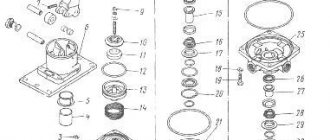
| Rice. 6.5. Vacuum booster: 1 – cover of the secondary chamber; 2 – piston of the secondary chamber; 3 – check valve; 4 – spring; 5 – nut; 6 – stop; 7 – rod; 8 – washer; 9 – rod seal; 10,12,37 – lock washers; 11 – sealing ring; 13 – sealing cuff of the cover; 14 – diaphragm plate; 15 – cover guide ring; 16 – cover of the primary chamber; 17 – support ring; 18 – diaphragm of the secondary chamber piston; 19 – connector; 20 – buffer; 21 – control valve diaphragm spring; 22 – diaphragm of the primary chamber piston; 23 – amplifier housing; 24 – piston of the primary chamber; 25 – valve body; 26 – thrust washer; 27 – housing guide ring; 28 – body sealing collar; 29 – valve piston; 30 – air filter; 31 – protective cover; 32 – pusher fork; 33 – pusher; 34 – spring bushing; 35 – valve spring; 36 – control valve seal; 38 – cotter pin; wire; 39 – valve diaphragm; 40 – stop screw; I, II – atmospheric cavities; III, IV – vacuum cavities |
| Rice. 6.6. Master brake cylinder: 1 – cover; 2 – gasket; 3 – mesh; 4 – tank; 5 – fitting; 6, 8, 15 – gaskets; 7 – plug; 9 – plug insert; 10 – spring; 11 – spring seat; 12 – washer; 13.19 – pistons; 14 – thrust bolt; 16 – spring holder; 17 – stop screw; 18 – sealing collar; 20 – sealing ring; 21 – thrust washer; 22 – retaining ring |
| Rice. 6.7. Signaling device: 1 – housing; 2 – fitting; 3 – switch; 4, 8 – gaskets; 5 – plug; 6 – long piston; 7 – short piston |
Drive of the service brake system (and
) includes a pedal, a vacuum booster (), a two-chamber master cylinder (), a warning device (), pipelines with connecting fittings and wheel cylinders.
| Rice. 6.8. Pressure regulator: 1 – piston; 2 – piston sealing ring; 3, 6 – piston spring support washers; 4 – piston spring; 5 – body; 7 – piston head seal; 8 – body bushing; 9 – pusher bushing support washer; 10 – pusher bushing; 11 – sealing ring of the pusher; 12 – support plate; 13 – pusher bushing spring; 14 – plug; 15 – plug gasket; 16 – bypass valve; 17 – plug; 18 – piston sleeve; 19 – retaining ring; 20 – protective cover |
On some vehicles, a pressure regulator ( ) can be installed in the hydraulic drive system, which automatically adjusts the brake fluid pressure in the rear wheel brakes depending on the load on the vehicle.
Maintenance
Constantly monitor the serviceability of the service brake system, adjust it in a timely manner and eliminate any malfunctions that arise.
Systematically check the fluid level in the master cylinder reservoirs and, if necessary, bring it up to normal. The level should be 15–20 mm below the upper edges of the filling holes. Make sure the connections of the hydraulic drive pipelines are tight. Check the condition of the pipelines and the reliability of the pipes on the frame and rear axle. During inspections, make sure that there is no damage to tubes and flexible hoses. Replace damaged pipes and hoses with new ones.
| Rice. 6.9. Pressure regulator drive: a – vehicles of the UAZ-31512 family; b – vehicles of the UAZ-3741, UAZ-3962, UAZ-2206, UAZ-3303 family and their modifications on UAZ-33036, UAZ-39094, UAZ-39095 vehicles, the regulator is installed on the opposite side of the frame cross member; 1 – pressure regulator; 2 – bracket (base); 3 – drive lever; 4 – adjusting bolt; 5 – elastic lever; 6, 9, and 13 – bolts; 7 – bushing; 8 – lever stand; 10 – spacer sleeve; 11 – terminal; 12 – rack bracket; 14 – lever axis |
During seasonal maintenance, check the operation of the pressure regulator. Clean the regulator from dirt and check the reliability of its fastening. By external inspection, make sure that the regulator and its drive parts are not damaged, there are no leaks of brake fluid and there are no gaps in the connection of the strut with the elastic lever and the bracket on the rear axle ( ).
When you press the brake pedal, piston 1 (see) of the pressure regulator should move out of the housing by 1.7–2.3 mm. Lack of piston stroke, as well as insufficient or excessive stroke, indicates a malfunction of the regulator or its drive.
When inspecting the hydraulic drive, pay attention to the location of the plastic (control) plug 17 and the absence of brake fluid leaking from under it. In normal condition, the plug should be recessed into the hole in the regulator body until it stops. The protrusion of the plug from the hole and the leakage of brake fluid mean a loss of tightness of the sealing rings 11 and, as a consequence, the functionality of the regulator.
As necessary, check the reliability of the vacuum booster, wash or replace the booster air filter.
Periodically remove the brake drums and clean the brake parts from dirt. In summer and when driving on dirty roads, clean more often.
When removing the brake drum, make sure that there are no leaks from the wheel brake cylinders, as well as that the wheel cylinders are securely attached to the shields. Pay attention to the condition of the wheel cylinder protective caps, the degree of wear of the friction linings, and the condition of the brake drum. If the surfaces of the linings become oily, clean them with sandpaper.
With the hubs removed, tighten the brake shield bolts.
Regularly flush the hydraulic drive and fill it with fresh brake fluid. To thoroughly flush the hydraulic drive, disassemble the main and wheel brake cylinders, the pressure regulator, and blow out the pipelines with compressed air.
When disassembling cylinders, maintain cleanliness. Wash rubber and metal parts of the cylinders in clean brake fluid. Do not use kerosene or gasoline, as this will cause swelling of the rubber parts and failure of the brake system. During assembly, it is recommended to lubricate the working parts of the cylinders with brake fluid.
Adjustment
To restore the normal size of the gaps between the pads and brake drums and reduce the pedal stroke, adjust the eccentrics, in which the hexagonal heads of the axles are brought out through the shield.
Adjusting the gaps between the pads and brake drums
(current adjustment) carry out in the following order:
1. Jack up the wheel whose brake mechanism needs to be adjusted.
2. While rotating the wheel, gradually turn the adjusting eccentric until the wheel brakes.
3. Gradually release the eccentric, turning the wheel until it rotates freely without the drum touching the pads.
4. Adjust the gaps between the pads and drums of the remaining brake mechanisms in the same way.
| Rice. 6.10. Adjusting the gaps between the brake pads and the front wheel brake drum |
When adjusting the front brakes and the front brake pads of the rear wheels, rotate the wheel forward ( ).
| Rice. 6.11. Adjusting the gaps between the pads and the rear wheel brake drum |
When adjusting the rear brake pads of the rear wheels, rotate the wheel backwards ( ).
To reduce the gaps, turn the eccentrics in the direction of rotation of the wheel, and to increase them, turn them against them.
5. Check while the car is moving that the brake drums do not heat up and that the brake mechanisms operate evenly when braking.
During the current adjustment, do not use the support pins, as this will disrupt the factory setting of the pads.
When replacing friction linings, adjust the installation of the pads.
Adjust the brakes when the brake drums are completely cool and the wheel bearings are properly adjusted.
Adjusting the pedal free play on vehicles of the UAZ-31512 family
do this by changing the stop position of switch 14 (see) of the brake signal.
| Rice. 6.4. Drive of the service brake system of vehicles of the UAZ-3741 family: 1, 20 – brackets; 2 – brake signal switch; 3 – nuts; 4 – buffer stop; 5 – pedal; 6 – intermediate fork; 7 – fork; 8 – lock nut; 9 – traction; 10 – cover; 11 – intermediate lever; 12 – tension spring; 13 – switch for the emergency signal lamp of the brake system; 14 – signaling device; 15 – housing of the main brake cylinder; 16 – tanks; 17, 19 – nuts; 18 – vacuum booster; 21 – pusher fork |
Adjusting the pedal free play on vehicles of the UAZ-3741 family
do this by changing the length of the vertical rod 9 (see) using forks 7, having previously unscrewed the lock nuts 8.
Check the free play of the pedal with the engine not running.
The free play of the pedal on UAZ vehicles is 5–14 mm, counting along its platform.
Filling the hydraulic brake system with fluid and checking the functionality of the system
Fill the hydraulic drive only with special brake fluid according to the instructions in the lubrication table in the following order:
1. Check the tightness of all hydraulic drive connections and the condition of flexible hoses.
2. Lift the hood (remove the radiator trim on a car of the UAZ-3741 family) and unscrew the caps of tanks 3 (see) and 16 (see) of the main cylinder. Fill the reservoirs with brake fluid.
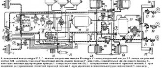
| Rice. 6.12. Bleeding the brake system |
3. Remove the rubber cap from the bypass valve of the brake cylinder of the right rear brake mechanism and place a rubber hose about 400 mm long onto the valve. Place the other end of the hose into a glass container with a capacity of at least 0.5 liters filled with brake fluid ( ).
4. Unscrew the bypass valve 1/2–3/4 turn, then press the pedal several times. Press the pedal quickly, release slowly.
Fluid under pressure from the master cylinder piston will fill the hydraulic drive and displace air. Bleed* until the release of air bubbles from the hose, lowered into a container with brake fluid, stops. While bleeding, add brake fluid to the master cylinder reservoirs, making sure to avoid exposing the bottom to prevent air from entering the system again.
Keep the end of the hose immersed in liquid during the entire filling operation.
5. Tightly tighten the wheel cylinder bypass valve while pressing the pedal, remove the hose and put on the cap.
* Bleed the hydraulic drive not only when it is filled with liquid, but also in case of depressurization of the hydraulic drive of the working cylinder of the rear brake mechanisms
6. Bleed the rear left brake cylinder, then the pressure regulator and the front brake cylinders. On the brake mechanisms of the front wheels, first the lower and then the upper cylinder are pumped.
7. Turn off the alarm device, do the following:
– unscrew the bypass valve of the right or left working cylinder of the rear brake mechanisms;
– gently press the pedal until the warning light on the instrument panel goes off; if the warning light flashes, this will mean that the indicator pistons have passed the neutral position, and therefore the operation must be repeated from the beginning, but only by unscrewing the front wheel bypass valve;
– close the valve while pressing the pedal.
After bleeding all brake mechanisms, add fluid to the master cylinder reservoirs to a level 15–20 mm below the upper edges of the filler holes.
Close the lids tightly.
| Note Do not add fluid to the brake master cylinder that is collected in a glass container during bleeding. |
If the brake fluid in the system is dirty, drain it and refill the system with fresh fluid. Do not press the pedal with the brake drum removed, as pressure in the hydraulic drive will force the pistons out of the wheel cylinders and fluid will flow out.
After filling the system with fluid, check the car for braking. With proper adjustment of the working brake mechanisms and correct bleeding of the hydraulic drive, full braking should occur within 1/2–2/3 of the pedal stroke, after which the foot should feel a “hard” pedal.
Repair
If there is significant wear or other malfunctions in the brake system parts, disassemble and check the condition of the parts and their suitability for further work. Replace worn and damaged parts. Use the data when repairing the system
.
Immerse brake pads with linings that become oily during operation in gasoline (unleaded) for 20–30 minutes. Then thoroughly clean the working surfaces of the pads with a wire brush and sandpaper. If the linings are heavily worn (0.5 mm left to the rivet heads), replace them with new ones. When replacing linings, grind their surface so that the diameter of the linings is 0.2–0.4 mm less than the diameter of the drum.
If there are deep grooves, scoring or uneven wear on the working surface of the drums, then bore the drum. When boring the drums, base it on the outer races of the hub bearings. An increase in the inner diameter of the drums by 0.8 mm after boring does not require a change in the diameter of the brake pads.
The maximum permissible diameter of the bored drum of the service brake mechanism is 281 mm.
When disassembling the wheel and master brake cylinders and pressure regulator, maintain cleanliness. Wash rubber and metal parts of the cylinders only in alcohol or brake fluid. Do not use kerosene or gasoline, as this will damage the rubber parts of the brake system.
After washing the parts, blow them with compressed air, but do not wipe them with a cloth to avoid fibers getting onto the working surface of the parts and losing their tightness. Before assembling, immerse the cuffs and O-rings in brake fluid.
Removal, disassembly and assembly of working brake mechanisms
During repairs, brake pads and wheel cylinders or parts included in them usually need to be replaced; to remove them, it is not necessary to completely remove the brake mechanisms.
Remove complete brake mechanisms from the vehicle only when they are completely replaced with new ones or when the axles are completely dismantled.
When installing the front wheel brakes on the vehicle, pay attention to the correct position of the shield. The upper cylinder should be tilted forward (from the vertical axis) at an angle of about 30° (on vehicles with final drive axles, the cylinders are positioned horizontally). When braking, the pads must be pressed out as the brake drum rotates as the vehicle moves forward. When installing rear wheel brakes on a car, the block with a long lining must be in front.
Removing and installing brake pads
do it in the following order:
1. Raise the car with a jack and remove the wheel whose brake pads need to be removed.
2. Remove the brake drum from the hub. To do this, unscrew the three screws securing the drum to the hub. If the drum is difficult to remove, then screw the removable bolts into the three special threaded holes in the disk and, tightening them evenly, remove the drum.
| Rice. 6.13. Removing and installing the brake pad tension spring |
3. Remove the brake pad tension spring using special pliers ( ).
4. Remove the upper release spring cups, springs, lower cups and remove the rods.
5. Unscrew the support pin nuts, remove the support pins, eccentrics and remove the brake pads.
Install the pads with new linings and assemble the brake mechanisms in the reverse order.
The brake drums are machined together with the hubs, so after removal, install them on the same hubs. Rearranging the brake drums from one hub to another will increase the runout of the working surfaces of the drum relative to the brake linings.
When installing the drum in place, before tightening the screws, you should firmly press the brake drum to the hub with the wheel nuts and only then tighten the screws. This is necessary to press the brake drum more tightly to the wheel hub.
Adjusting the installation of brake pads
do it in the following order:
1. Jack up the wheel whose brake mechanism needs to be adjusted.
2. Slightly unscrew the support pin nuts and set the support pins to their initial position (the marks on the ends of the support pins should be located as indicated in and ).
| Rice. 6.14. Adjusting the rear wheel brake pads using support pins |
3. Pressing the pedal with a constant force of 118–147 N (12–15 kgf), turn the support pins so that the ends of the shoes on the pin side rest against the brake drum ( ). Determine the moment of contact of the pads with the drum by the increase in resistance when turning the support pin. In this position, tighten the support pin nuts, being careful not to turn the pins.
4. Turn the adjusting eccentrics until the pads touch the brake drum until the wheel brakes.
5. After stopping pressing the pedal, turn the adjusting eccentrics in the opposite direction so that the wheels rotate freely, without the drum touching the pads.
When correctly installing new pads with unworn brake drums, the “a” marks on the support pins should be located as shown in and or with deviations from this position in one direction or the other up to 50°.
When installing new pads, when the friction linings have not yet been run in to the surface of the drums, the brake drums may heat up slightly after the indicated adjustment. After several braking sessions the pads will break in and the heating will stop. If the brake drums become very hot, move the pads slightly away from the brake drum using the adjusting eccentrics.
Removing and disassembling wheel brake cylinders
do it in the following order:
1. Disconnect the pipeline from the cylinder and remove the cylinder.
2. Remove the cylinder protective caps, take out the pistons with sealing rings and springs.
Assembly and installation of wheel brake cylinders
do in reverse order.
Removing and disassembling the master cylinder
do it in the following order:
1. Disconnect the pipelines leading from the master cylinder to the warning device.
2. Disconnect the warning device from the master cylinder.
3. Disconnect the brake master cylinder from the vacuum booster.
4. Unscrew the thrust bolt 14 (see).
5. Remove the lock ring 22 and take out the thrust washer 21.
6. Remove the primary chamber piston assembly 19.
7. Unscrew plug 7, remove plug insert 9, return spring 10 and secondary chamber piston assembly 13.
It is not recommended to remove tanks 4 unless necessary. If necessary, to remove them, unscrew the plugs of the tanks 1, remove the screens 3 and unscrew the fittings 5 securing the tank bodies.
Remove piston assembly 19 only towards the flange, and piston assembly 13 towards the opposite end. Remove the pistons carefully so as not to damage the sealing collars 18 and rings 20. If the pistons cannot be removed freely from the cylinder, first lightly push the piston 13 with the piston 19, and then carefully push the piston 19 by pressing (through the vacated cavity) with a screwdriver or other object onto the spring holder 16 or spring holder screw 17.
Reassemble and install the master cylinder in the reverse order. In this case, install the assembled pistons into the cylinder carefully and only from the side of the corresponding ends of the cylinder. To avoid damaging the seals and rings, do not push the pistons through the entire cylinder cavity.
When assembling piston 19, screw screw 17 until it stops in the piston. Screw the thrust bolt 14 into the crankcase only after installing the assembled piston 19, washer 21 and retaining ring 22.
Tightening torques:
thrust bolt 14…..8–10 N m (0.8–1.0 kgf m);
fitting 5…..16–22 N m (1.6–2.2 kgf m);
plugs 7…..167–186N·m (17–19 kgf·m).
Removing and disassembling the pressure regulator
do it in the following order:
1. Disconnect the lines leading to the regulator.
2. Disconnect the regulator from the bracket (base).
3. Unscrew plug 14 (see) from the end of the housing.
4. Remove the protective cover 20 and the locking ring 19.
5. Remove piston 1 from the housing with all internal parts.
6. Unscrew the bypass valve 16.
It is not recommended to remove control plug 17 unless necessary. Remove the piston from the housing carefully towards the end under the protective cover so as not to damage the sealing rings. If the piston cannot be removed freely from the housing, first lightly push it from the end under the plug.
Assemble and install the regulator in the following order:
1. Assemble piston 1 with seal 7 (see).
2. Install body bushing 8, assembled piston with seal, support washer 6, piston spring 4, support washer 3, sealing ring 2, piston bushing 18 and retaining ring 19 into the regulator body 5.
3. Install support washer 9, sealing ring 11, pusher bushing 10, second sealing ring 11, support plate 12 and bushing spring 13 into the regulator body.
4. Assemble plug 14 with gasket 15 and screw it into the regulator body.
5. Screw bypass valve 16 into the regulator body.
6. Install the protective cover 20, the bypass valve cap and the control plug 17 (if it was removed).
Tightening torques:
plugs 14…..43–57 N m (4.4–5.8 kgf m);
valve 16…..10–14 N m (1.0–1.4 kgf m).
Removing and installing the pressure regulator drive. It is not recommended to remove the pressure regulator drive from the vehicle unless necessary, so as not to disrupt its adjustment. In case of dismantling during assembly, it is necessary to maintain the installation dimensions given on. In this case, set dimension H (the position of the elastic lever 5 relative to the bracket 2) using the adjusting bolt 4 on the pressure regulator assembled with bracket 2, drive lever 3, elastic lever 5 and terminal 11 (before installation on the car).
Tightening torques:
bolt 13 and nuts, bolts 4, 13 and axle 14……..27–35 N m (2.8–3.6 kgf m);
bolts securing the regulator to bracket 2 and bolt nuts 9……..14–18 N·m (1.4–1.8 kgf·m);
bolt nuts 6……..6.4–8.0 N·m (0.65–0.8 kgf·m).
Removal, disassembly and assembly of the vacuum amplifier
If the amplifier fails, only the force from the driver’s foot is transmitted to the pistons of the master cylinder through pusher 33 (see ), control valve, buffer 20 and rod 7.
Increased pedal force indicates the need for inspection and possibly repair of the amplifier.
If seals, springs and other parts fail, remove the amplifier from the car, first disconnecting the master brake cylinder, hose, pedal from it and disassemble it. Before disassembling, mark the body and cover so that they can be reinstalled in their original positions during reassembly.
Disassemble and reassemble the amplifier in a special fixture using a small press.
Install the amplifier with four bolts with rubber bushings put on them to protect the threads from damage in the holes of the stationary plate. On the two bolts of the secondary chamber cover, having also previously secured their threads, install a special lever with holes for these bolts and, pressing it with a little force with a press, turn the cover until the protrusions on the amplifier body align with the depressions on the cover.
Other operations do not require special devices.
When assembling, lubricate the working friction surfaces of parts 6,17, 24, 25 and the contacting surfaces of cover 1 with diaphragm 18 with CIATIM-221 lubricant.
After assembly, check the amplifier for functionality and tightness. To do this, attach a hose to the check valve and, with the engine running, apply a force of 196–294 N (20–30 kgf) to pusher 33. In this case, the control valve body together with the pusher should move until it stops.
After removing the force from pusher 33, the control valve body should return to its original position. After 2–3 minutes after stopping the engine, when you press pusher 33, you should hear the hiss of air entering the amplifier through the control valve.
Before installing the master brake cylinder on the booster, adjust the extension of the rod 7 relative to the mating plane of the cover 1 to 7.78–8 mm and the extension of the pusher 33 relative to the mating plane of the body 23 to 134.7–136.3 mm.
↓ Comments ↓
1.Operation and Maintenance
1.0 Operation and maintenance 1.1 Maintenance 1.2 Scope of work by type of maintenance 1.3 Vehicle lubrication
2. General information
2.0 General information
3. Engine
3.0 Engine 3.1 Crank mechanism 3.2 Possible engine malfunctions, their causes and methods of elimination 3.3 Gas distribution mechanism 3.4 Lubrication system 3.5 Cooling system 3.6 Power system 3.7 Exhaust system 3.8 Engine mounting 3.9 Checking the technical condition of the engine
4. Transmission
4.0 Transmission 4.1. Clutch 4.2. Gearbox 4.3. Transfer case 4.4 Drive axles 4.5. Rear axle 4.6. Front axle 4.7 Axles with final drives
5. Chassis
5.0 Chassis 5.1. Car suspension 5.2. Hubs, wheels and tires
6. Steering
6.0 Steering 6.1 Maintenance 6.2 Possible steering malfunctions, their causes and solutions
7. Brake system
7.0 Brake system 7.1 Service brake system 7.2 Possible malfunctions of the service brake system, their causes and methods of elimination 7.3 Parking brake system 7.4 Possible malfunctions of the parking brake system, their causes and methods of elimination
8. Electrical equipment
8.0 Electrical equipment 8.1 Battery 8.2 Possible malfunctions of the battery, their causes and methods of elimination 8.3 Generator 8.4 Possible malfunctions of the generator, their causes and methods of elimination 8.5 Possible malfunctions of the voltage regulator, their causes and methods of elimination 8.6 Starter 8.7 Possible malfunctions of the starter, their causes and methods elimination 8.8 Non-contact ignition system 8.9 Possible malfunctions of the ignition system, their causes and methods of elimination
9. Car body and cabin
9.0 Body and cabin of vehicles 9.1 Body of vehicles of the UAZ-31512 family 9.2 Body and cabin of vehicles of the UAZ-3741 family 9.3 Frame and towing device
10. Applications
10.0 Applications 10.1 Appendix 1. rolling bearings used in components and assemblies of automobiles 10.2 Appendix 2. special tools and devices for disassembling and assembling components and assemblies of automobiles