The pneumohydraulic booster of the Ural-4320 car is an integral part of the clutch system of this car, reducing the force applied to the pedal. The CCGT consists of three units:
- pneumatic cylinder;
- tracking system;
- indicator of lining wear on the driven disk.
During operation, the pressure of the liquid that is inside the main cylinder is transferred to the CCGT. As a result, the amplifier pistons and tracking devices are activated. At the moment of release, the pressure on the tracking system piston decreases, as a result of which this mechanism, together with the PSU piston, returns to the initial position.
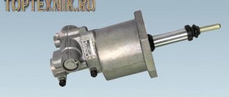
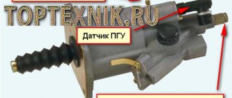
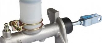
PGU device (pneumohydraulic clutch booster)
The pneumatic hydraulic booster of the clutch drive is used to reduce the force applied to the clutch pedal by the driver.
- hydraulic cylinder with piston, rod and spring;
- a pneumatic cylinder with a piston, a rod (common with the hydraulic cylinder piston) and a return spring;
- a follower mechanism consisting of a follower piston with a cuff, a diaphragm (sandwiched between two parts of the housing), in the center of which the exhaust valve seat is attached, a diaphragm return spring;
- exhaust and intake valves (mounted on one rod) with a return spring;
- intake valve seats;
- a hole closed with a seal to prevent dirt from entering, connecting the above-piston cavity of the pneumatic cylinder with the environment.
When the clutch is engaged, the common rod is pressed against the pistons of the hydraulic cylinder and pneumatic cylinder. The piston of the follower mechanism occupies a position corresponding to the open exhaust valve connecting the above-piston space of the pneumatic cylinder with the environment and the closed inlet valve.
When the clutch is disengaged, the working fluid from the master cylinder enters the hydraulic cylinder of the pneumatic hydraulic booster, and at the same time through the channel to the piston of the follower mechanism. Fluid pressure moves the piston toward the exhaust valve seat. The diaphragm, bending, moves the seat to the exhaust valve, which sits in the seat, isolating the above-piston space of the pneumatic cylinder from the environment.
Next, the force from the exhaust valve is transmitted through the rod to the intake valve, which opens, and the compressed air flows through the channel into the above-piston space of the pneumatic cylinder. The piston of the pneumatic cylinder, mixing, acts on the piston rod of the hydraulic cylinder. The piston transmits force to the pusher, which acts on the clutch release fork lever. Part of the compressed air enters the diaphragm cavity.
Thus, the follower piston is under the action of two oppositely directed forces: the action of the working fluid on one side and the compressed air on the other. The pistons of the follower mechanism and the pneumatic cylinder are selected to ensure the necessary reduction in the force on the clutch pedal.
When the clutch pedal is released, the pressure of the working fluid drops, and all parts return to their original position under the action of return springs; the above-piston space of the pneumatic cylinder communicates with the environment through the open exhaust valve.
If the pneumatic system fails, the hydraulic cylinder piston moves only under the pressure of the working fluid.
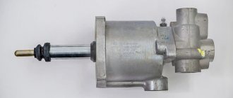
KamAZ-5320, PGU: design and principle of operation
What is the KamAZ-5320 PGU device? This question interests many beginners. This abbreviation may confuse an ignorant person. In fact, the PGU is a pneumatic hydraulic power steering. Let's look at the features of this device, its operating principle and types of maintenance, including repairs.
- 1 – spherical nut with lock nut.
- 2 – piston pusher of the clutch deactivator.
- 3 – protective cover.
- 4 – clutch release piston.
- 5 – back part of the frame.
- 6 – complex seal.
- 7 – follower piston.
- 8 – bypass valve with cap.
- 9 – diaphragm.
- 10 – inlet valve.
- 11 – graduation analogue.
- 12 – pneumatic type piston.
- 13 – drain plug (for condensate).
- 14 – front part of the body.
- “A” – supply of working fluid.
- “B” – supply of compressed air.
Purpose and device
A truck is a fairly massive and large-sized vehicle. Controlling it requires remarkable physical strength and endurance. The KamAZ-5320 PGU device makes it easier to adjust the vehicle. This is a small but useful device. It makes it possible not only to simplify the driver’s work, but also increases work productivity.
The node in question consists of the following elements:
- Piston pusher and adjusting nut.
- Pneumatic and hydraulic piston.
- Spring mechanism, gearbox with cover and valve.
- Diaphragm seats, control screw.
- Bypass valve and piston follower.
Peculiarities
The amplifier housing system consists of two elements. The front part is made of aluminum, and the rear part is made of cast iron. A special gasket is provided between the parts, which acts as a seal and diaphragm. The follower mechanism automatically regulates the change in air pressure on the pneumatic piston. This device also includes a sealing collar, springs with diaphragms, as well as inlet and outlet valves.
Operating principle
When the clutch pedal is pressed under fluid pressure, the KamAZ-5320 PGU device presses on the rod and piston of the follower, after which the structure, together with the diaphragm, moves until the intake valve opens. The air mixture from the vehicle's pneumatic system is then supplied to the pneumatic piston. As a result, the forces of both elements are summed up, which allows you to retract the fork and disengage the clutch.
After the foot is removed from the clutch pedal, the pressure of the supply main fluid drops to zero. As a result, the load on the hydraulic pistons of the actuator and follower mechanism is reduced. For this reason, the hydraulic piston begins to move in the opposite direction, closing the inlet valve and blocking the flow of pressure from the receiver. The pressure spring, acting on the follower piston, moves it to its original position. The air initially reacting with the pneumatic piston is released into the atmosphere. The rod with both pistons returns to its initial position.
Production
The KamAZ-5320 PGU device is suitable for many model modifications of this manufacturer. Most old and new tractors, dump trucks, and military variants are equipped with pneumatic-hydraulic power steering. Modern modifications produced by various companies have the following designations:
- Spare parts for KamAZ (PGU) manufactured by KamAZ OJSC (catalog number 5320) with vertical placement of the tracking device. The device above the cylinder body is used on variations under the index 4310, 5320, 4318 and some others.
- WABCO. CCGT units under this brand are manufactured in the USA and are distinguished by their reliability and compact dimensions. This equipment is equipped with a system for monitoring the condition of the linings, the level of wear of which can be determined without dismantling the power unit. Most trucks with a 154 series transmission are equipped with this type of air-hydraulic equipment.
- Pneumatic hydraulic clutch booster "VABKO" for models with ZF type gearbox.
- Analogues produced at a plant in Ukraine (Volchansk) or Turkey (Yumak).
In terms of choosing an amplifier, experts recommend purchasing the same brand and model that was originally installed on the machine. This will ensure the most correct interaction between the amplifier and the clutch mechanism. Before changing the unit to a new variation, consult a specialist.
Service
To maintain the operating condition of the unit, carry out the following work:
- Visual inspection to detect visible air and fluid leaks.
- Tightening the fixing bolts.
- Adjust the free play of the pusher using a spherical nut.
- Adding working fluid to the system tank.
It is worth noting that when adjusting the KamAZ-5320 PGU of the Wabco modification, the wear of the clutch linings is easily visible on a special indicator extended under the influence of the piston.
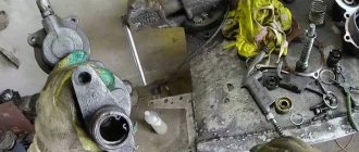
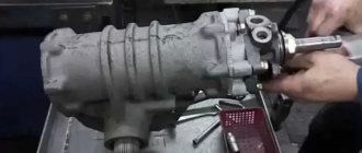
Disassembly
This procedure, if necessary, is performed in the following order:
- The back of the body is clamped in a vice.
- The bolts are unscrewed. Remove the washers and cover.
- The valve is removed from the body part.
- The front frame is dismantled along with the pneumatic piston and its membrane.
- The following are removed: the diaphragm, the follower piston, the retaining ring, the clutch release element and the seal housing.
- The bypass valve mechanism and the hatch with the outlet seal are removed.
- The frame is removed from the yews.
- The thrust ring of the rear part of the housing is dismantled.
- The valve stem is freed from all cones, washers and seats.
- The follower piston is removed (you must first remove the stopper and other related elements).
- The pneumatic piston, cuff and retaining ring are removed from the front part of the housing.
- Then all parts are washed in gasoline (kerosene), sprayed with compressed air and go through the defect detection stage.
PGU KamAZ-5320: malfunctions
Most often, the following problems occur in the node in question:
- The compressed air flow is supplied in insufficient quantities or completely absent. The cause of the malfunction is swelling of the inlet valve of the pneumatic booster.
- Jamming of the follower piston on the pneumatic booster. Most likely, the reason lies in the deformation of the o-ring or cuff.
- There is a “failure” of the pedal, which does not allow the clutch to be completely disengaged. This problem indicates that air has entered the hydraulic drive.
Repair of KamAZ-5320 PGU
When troubleshooting the elements of a unit, special attention should be paid to the following points:
- Checking sealing parts. Deformations, swelling and cracks are not allowed on them. If the elasticity of the material is impaired, the element must be replaced.
- Condition of the working surfaces of the cylinders. The internal clearance of the cylinder diameter is monitored, which in fact must comply with the standard. There should be no dents or cracks on the parts.
The CCGT repair kit includes the following KamAZ spare parts:
- Protective cover for rear housing.
- Cone and diaphragm of the gearbox.
- Cuffs for pneumatic and follower piston.
- Bypass valve cap.
- Retaining and sealing rings.
Before installation, it is recommended to treat all parts with Litol type lubricant.
Replacement and installation
To replace the node in question, perform the following manipulations:
- The air is being bled from the KamAZ-5320 CCGT unit.
- The working fluid is drained or the drain is blocked using a plug.
- The clutch spring fork is removed.
- The water and air supply pipes are disconnected from the device.
- The fastening screws to the crankcase are unscrewed, after which the unit is dismantled.
After replacing deformed and unusable elements, the system is checked for leaks in the hydraulic and pneumatic parts. Assembly is carried out as follows:
- Align all the fixing holes with the sockets in the crankcase, after which the amplifier is secured using a pair of bolts with spring washers.
- The hydraulic hose and air line are connected.
- The release spring mechanism of the clutch release fork is mounted.
- Brake fluid is poured into the compensation reservoir, after which the hydraulic drive system is pumped.
- Re-check the tightness of the connections for leakage of working fluid.
- If necessary, adjust the size of the gap between the end part of the cover and the travel limiter of the gear divider activator.
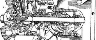
Schematic diagram of connection and placement of node elements
The operating principle of the KamAZ-5320 PGU is easier to understand by studying the diagram below with explanations.
- a – standard diagram of interaction of drive parts.
- b – location and fixation of node elements.
- 1 – clutch pedal.
- 2 – main cylinder.
- 3 – cylindrical part of the pneumatic amplifier.
- 4 – follower mechanism of the pneumatic part.
- 5 – air duct.
- 6 – main hydraulic cylinder.
- 7 – release clutch with bearing.
- 8 – lever.
- 9 – rod.
- 10 – drive hoses and pipes.
The unit in question has a fairly clear and simple structure. Nevertheless, its role when driving a truck is very significant. The use of a PSU can significantly facilitate machine control and increase the efficiency of the vehicle.
fb.ru
MAZ clutch PGU, device, diagram - manufactured by Spetsmash.
If there were no such overloads after installing (replacing) the amplifier, another version immediately arises - they slipped a defective one! And what, today everyone is counterfeiting, even some
or 238, even though the Brabus SV12 is assembled for the 600th gelding. Probably, only components for the Russian “Kalina” and the Ukrainian “Tavria” are not counterfeited - the material is more expensive.
If this distance is less than 50 mm, then this means that during operation the rod plunger will extend all the way, thereby opening the outlet of the liquid. All that is required is to move the lever one slot closer to the amplifier. If the distance is greater, then the reason for the leakage is different, and it is better to carry out a more detailed check at a car service center. However, we repeat, but most often there will be plenty of adjustment.
1 6430-1609205 Cylinder body 2 6430-1609324 Cuff 3 6430-1609310 Ring 4 6430-1609306 Washer 5 6430-1609321 Cuff 6 6430-1609304 Bushing 7 Ring 033-036- 19-2-2 Ring 033-036-19-2 -2 8 6430-1609325 Cuff 9 Ring 018-022-25-2-2 Ring 018-022-25-2-2 10 6430-1609214 Follower piston 11 Ring 025-029-25-2-2 Ring 025-029- 25-2-2 12 6430-1609224 Spring 13 Ring 027-03 0-19-2-2 Ring 027-03 0-19-2-2 14 6430-1609218 Seat 15 500-3515230-10 Clutch booster valve 16 842- 8524120 Spring 17 Ring 030-033-19-2-2 Ring 030-033-19-2-2 18 6430-1609233 Support 19 6430-1609202 Cylinder 20 373165 Pin M10x40 21 6430-1609203 G Ilsa 22 375458 Washer 8 OT 23 201458 Bolt М8-6gх25 24 6430-1609242 Spring 25 6430-1609322 Cuff 26 6430-1609207 Piston 27 6430-1609302 Ring 28 Ring 020-025-30-2-2 Ring 020-025-30-2-2 29 6430-1609236 Shaft 30 6430-1609517 Seal 31 6430-1609241 Rod 32 6430-1609237 Cover 33 6430-1609216 Cylinder plate 34 220050 Screw M4-6gx8 34 220050 Screw M4-6gx8 35 64221- 1602718 Protective cap 36 378941 Plug M14x1.5 37 101-1609114 Bypass valve 38 12-3501049 Valve cap 39 378942 Plug M16x1.5 40 6430-1609225 Breather 41 252002 Washer 4 42 252132 Washer 14 43 262541 Plug kg 1/8″ 43 262541 Plug kg 1/8″ 44 Ring 008-012-25-2 -2 Ring 008-012-25-2-2 45 6430-1609320 Tube 46 6430-1609323 Seal 46 6430-1609323 Seal Link to this page: https://www.kspecmash.ru/catalog.php?typeauto=2&mark= 11&model=293&group=54
Hydropneumatic clutch drive
Clutch and brake control drive
1. Compensation tank. 2. Tank cover. 3. Bolt. 4. Nut. 5,14,23. Bracket. 6. Cylinder stop. 7. Main cylinder. 8. Pedal mechanism. 9,32,37,51,54,59. Springs. 10. Brake pedal. 11. Clutch pedal stop. 12.15. Brake pedal rods. 13. Brake valve control lever. 16,24,33. Hoses. 17,19,22,31. Clutch drive pipes. 18. Triple protective valve. 20. Air cylinder. 21. Check valve. 25. Clutch fork shaft lever. 26. Rod. 27. Pneumohydraulic booster (PTU). 28. Bleeding valve. 29. Bracket thrust bolt. 30. Clutch pedal. 34,53,64. Cases. 35. Cap. 36. Control valve.
38.65. Piston. 39. Cover. 40. Wiper. 41.49. Forks. 42. Nut. 43. Guide ring. 44.66. Cuffs. 45. Exhaust window. 46.67. Retaining rings. 47,48,58,63. O-rings. 50,56,57. Traffic jams. 52. Air valve. 55. Spool. 60. Spring cup. 61. Pressure spring. 62. Underwater fitting. 68. Protective cover. 69. Pusher. 70. Ring. 71. O-ring.
B,C,D,F,K,V,M. Cavities. a. compressed air supply b. supply of working fluid
Data for monitoring and adjustments
d=0.2-0.6 mm L=185-200 mm L1=289 mm L2=30-40 mm
When replacing brake fluid or repairing the hydraulic part of the drive, bleed the system in the following order: - fill compensation tank 1 with brake fluid; - remove the protective cap 35, put the bleeding hose on the valve 28, unscrew the valve 1/2-3/4 turn and immerse the end of the hose in a clean, transparent container with brake fluid;
- loosen nut 4 and when the first drops of liquid appear, tighten; - sharply press the clutch pedal 30 with the valve open and slowly release with the valve closed until air bubbles stop coming out of the hose. If the release of air bubbles with liquid has stopped, tighten the bleeder valve. To prevent air from being sucked into the main cylinder when pumping, you need to ensure that the liquid level in the compensation tank is always more than half, and the end of the hose is constantly in the liquid. The criterion for complete pumping is a sharp increase in the force on the pedal when it moves by an amount of L = 35-40 mm after selecting free play.
PGU KAMAZ | clutch, repair, malfunctions
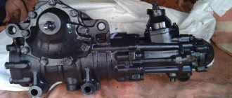
This device is installed on special feet located on the right side of the clutch housing. This arrangement allows you to achieve greater efficiency of the amplifier itself and make the most of the space. In terms of design, the KamAZ CCGT unit does not look too complicated, and this unit consists of the following elements:
– two connected buildings; – release piston with pusher; – pneumatic piston; – follower piston; – diaphragm and gearbox valves.
Five bolts are used to connect the front and rear housings, and a diaphragm is installed at the connection point. Both housings have machined holes for the pistons; these holes are sealed with covers and/or sealing elements. The work of KamAZ PGU consists of the following...
When the driver presses the pedal, the working fluid enters under pressure into the cavity of the cylinder of the switching piston, and then passes to the tracking piston. It begins to shift, and at the same time puts pressure on the diaphragm spring, shifting its seat. When the diaphragm seat moves, the outlet valve of the gearbox is closed and the inlet valve is released.
Consultation on technical issues, purchase of spare parts 8-916-161-01-97 Sergey Nikolaevich
As a result, compressed air enters the space above the piston and into the cavity of the diaphragm, and two counter-directional forces begin to act on the follower piston. As a result, to fully press the pedal, a force of only about 15 kgf is required. If for some reason there is no air, then to depress the clutch you will have to apply a force equal to 70-90 kgf.
By the way, if we talk about the most common malfunctions for KamAZ CCGT units, it is not even the deformation of the pistons, or a manufacturing defect, but the swelling of the sealing rings, which results in leakage of the working fluid and contamination of the internal cavities.
If it so happens that you have problems with the KamAZ clutch PGU, or with the clutch itself, then use only high-quality spare parts for repairs. Such as we offer you - . All our spare parts for the clutch and brake system of KamAZ vehicles have an increased service life (up to 100 thousand km), which is confirmed by numerous checks and, as a result, MADI certificates.
KAMAZ PGU device
Hydraulic clutch - a ready-made solution?
https://ru.aliexpress.com/item/Atv-accessories-big-pump-brake-bull-atv-re. Look what I found. As I understand it, when pressure is applied, this device will pull the cable towards itself, which is what we need. Do you think it will work?
- Login or Register
If you can find a working cylinder, it will work. Well, you still need to have enough movement. But what for a goat button accordion? You may also have problems with the hydraulic system and the cable may still break. It is necessary to make a hydraulic coupling without any rods or levers, so that it puts pressure directly on the release lever. Fewer parts means fewer problems.
- Login or Register
You still need a lever, otherwise the force will be too great.
- Login or Register
interesting thing. But Alex is right, the cable remains. Here's where to get a compact hydraulic cylinder with a stroke of 15 millimeters in order to minimize cables and other body kits. ___________________________________________________________________ “Man can be destroyed, but he cannot be defeated” (E. Hemingway)
- Login or Register
Why does the Urals need a hydraulic clutch at all?
- Login or Register
You still don't understand this? The answer is simple - so that it’s not like everyone else