Both cavities of the cylinder communicate with each other through a distributor; the piston can move freely and float under the influence of the gravity of the mounted implement, which copies the field relief with the support wheel.
They cut off the discharge channel from the cavities, and the oil liquid is not able to get to the cylinders. In this case, the distributor is removed from the tractor and replaced with a new one.
Three ball retainers 7 fit into the upper recess of the cage and are held in this position by bushing 6. This is not recommended, since not only the conical locking part of the valve wears out, but also its seat. On our new website you can see all the equipment, equipment and place an order! The discharge inlet hose of the throttle-flow meter is connected to the discharge fitting of the high-pressure pump being tested, and the drain hose is lowered into the hydraulic system tank.
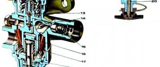
The distributor consists of a cast iron body 12 fig.
If there is significant shrinkage of the rod with a working distributor or the mounted implement rises jerkily, then the power cylinder is removed and disassembled for technical examination of the parts. This allows you to move the piston in the cylinder by external force and, under the influence of its own gravity, lower the mounted machine or the working body of a hydraulically powered trailed machine, as well as follow the soil topography with the support wheels of the mounted machine, ensuring a constant tillage depth.
The oil approaches the valve through the inclined and axial drillings in the spool. It is possible to grind the conical surface of the valve in the centers of the lathe, fig.
The spools are controlled using levers 7 located in the bottom cover. The pusher moves the locking sleeve 6, compressing the spring 4. What kind of valve is it and what is its function on the hydraulic distributor? Tractor MTZ-82.
We recommend: how to adjust valves on MTZ
Design and principle of the hydraulic system
The advantages of a tractor over other equipment are well known: versatility, the ability to work with different attachments and trailers. It is the hydraulic system that makes it possible to aggregate, that is, combine the tractor with mounted and semi-mounted working equipment, various trailers and semi-trailers equipped with hydraulic mechanisms. Due to oil pressure - the working fluid of the system - manipulation of all attachments is ensured: bulldozer blades, buckets, plows and harrows, organs for planting and harvesting. The basis of the hydraulic system is a hydraulic pump and a distributor.
The pump creates the necessary pressure in the system, which makes it possible to control additional equipment and trailers. To avoid overload, it operates only at low engine speeds. The pump is located on the body of the hydraulic units, secured with studs, and centering is ensured by a special glass. The drive is connected to the intermediate gear of the power take-off shaft (PTO).
Principle of operation:
- Due to the rotation of the gears, the pump creates a vacuum in the suction zone.
- The rarefied air is discharged into the discharge hole located between the gear teeth and the pump housing.
- The required pressure is created due to the difference in the diameters of the discharge and suction holes.
The distributor performs the following functions:
- Directs oil from the hydraulic pump to the consumer (equipment or trailer).
- Ensures that the system switches to idle mode by redirecting oil to the tank.
- Limits pressure, thereby protecting the hydraulic system from overload.
The safety valve is activated when the pressure in the MTZ 82 hydraulic system increases to 135 kgf/cm².
Operating modes of the hydraulic distributor:
- Neutral (system unloading due to the bypass valve).
- Lifting - the safety valve opens, the spool spring is pressed out and oil from the tank enters the lower part of the cylinders. As a result, the attachment moves to the up position.
- Forced Lowering - The valve closes, preventing oil from entering the cylinder and causing the equipment to lower.
- Floating - the working element lowers under the influence of its own weight.
The MTZ 82 hydraulic tank is a cast iron body with one top and two side covers. A pump with a drive is attached to the lower part. The tank volume is 6 liters and is refilled with universal seasonal oils. The oil level is checked by an oil gauge using three marks: O - minimum permissible level, P - upper level, C - upper level for working with dump trailers and haystack throwers.
The general hydraulic structure is organized according to the separate-aggregate type. This means that the mounted hydraulic system and the power steering (power steering) system are controlled separately. This ensures the same ease of control regardless of the type and mode of operation of the hitch or trailer.
Essential elements
The system consists of several components that perform their functions. All of them are very important:
- pump. It is used to convert engine energy through a drive into the energy of a fluid flow, which moves and creates pressure. It is installed on the hydraulic unit body using studs, after which it is centered. A special glass is used for this. In MTZ tractors, PTO intermediate gears are used as a drive;
- distributor. Controls flows in the system under external influence. Performs several functions. Firstly, it transfers oil to consuming devices (cylinder, hydraulic motor, trailer). Secondly, it serves as a switch to idle mode. To do this, the liquid is redirected to the tank. Limits pressure when overload occurs.
- power hydraulic cylinders. Raise, lower or hold attachments and trailers;
- hydraulic boosters. They regulate the adhesion weight by applying load to the drive wheels to reduce slipping;
- oil tanks. They are containers for storing oil on which other units are mounted;
- position-force regulators. Used to control agricultural machines and implements directly from the cab. Used to reduce fuel consumption and increase productivity;
- locking devices. Prevents lubricant from leaking out of the oil line;
- breakaway couplings. Used when the forces applied to the disconnecting hoses are exceeded to avoid breakages;
- connecting fittings. Pipelines connect structural elements.
You can buy spare parts for the MTZ 82 tractor and other models in the catalog of our online store.
Hydraulic system diagram
The general structure of the system includes:
- gear pump for hydraulics NSh-32-2;
- distributor Р75-33-Р;
- main cylinders Ts100 and two remote cylinders Ts75;
- power regulator providing four operating modes;
- hydraulic adhesion weight increaser (GWI), which reduces wheel slip and facilitates the operation of equipment;
- a hydraulic accumulator that serves to maintain pressure and replenish possible oil leaks;
- locking devices;
- MTZ hydraulic breakaway coupling (2 pcs);
- hydraulic tank (oil reservoir);
- oil filter;
- fastening fittings.
The pump is connected to the tank, distributor and power regulator. The suction pipe goes to the tank, and the oil discharge pipes go to the distributor and regulator. The oil flow is directed by a distributor either to the tank or to the fuel pump and then through the regulator and power cylinder it is supplied to the hydraulic drive of the trailer or attachment. As a result, the working body (blade, bucket, mower) moves in accordance with the operator’s commands.
Hydraulic diagram MTZ-82.1
The Belarus MTZ-82.1 hydraulic attachment system includes:
- Hydraulic tank equipped with a filter.
- Hydraulic system pump - creates the required oil pressure necessary for the system to operate.
- Spool valve.
- Power hydraulic cylinders – control the raising and lowering of the attachment.
- Position-force regulator – necessary to control the position of the tractor and its attached parts.
- Drain oil line.
- Rear mounted unit.
The diagram of the MTZ-82.1 hydraulic system is presented below.
Possible faults
Proper operation of the system is ensured by the use of suitable parts and consumables, as well as timely maintenance. Maintenance comes down to regular oil changes, as well as checking the condition of parts, linings and oil lines.
The oil is changed once a season or after every 2000 operating hours. First start the engine until the oil warms up to 30° C. Then turn off the engine and drain the used oil through the drain hole in the bottom of the crankcase. The hydraulic oil filter is removed and washed in diesel fuel. The washed filter is put back in place and fresh oil is added until about. The recommended brand of hydraulic oil for MTZ 82 is M-8G2K, M-10G2K, M-10G2. At the final stage, start the engine and lower and raise the rear linkage mechanism several times to bleed the hydraulic system.
Basic malfunctions and their elimination
Malfunctions in hydraulic distributors can cause a decrease in their operating efficiency or complete failure. Listed below are the main faults and how to resolve them.
Reset the safety valve.
Due to such a failure, the protection system is triggered prematurely. To avoid such a situation, you should set the pressure according to the instructions, that is, in the following sequence:
- Connecting a pressure gauge to the pressure cavity of the distributor;
- Increased load;
- Turn the adjusting screw until the pressure is established at the required level - it should be taken into account that to increase the pressure, the screw must be turned clockwise, and to decrease it - counterclockwise.
The hydraulic distributor should be adjusted at maximum engine speed.
Bypass channel stuck.
In this case, the distributor must be disassembled and all components and assemblies washed. The valve pressure should be set to 13-16 MPa, depending on the model and manufacturer of the device.
MTZ hydraulic distributor - design, purpose and its diagram
Back in 1974, the first MTZ 80 wheeled tractors rolled off the assembly line at the Minsk Tractor Plant, which were distinguished by their versatility when performing agricultural work. Its features such as rear axle drive, front-mounted engine compartment, 18 forward and 4 reverse gears, as well as ease of maintenance and repair, made it popular not only in the fields, but also in production, construction, housing and communal services. and forestry. The long history of production of these machines is due to the fact that their design allows the use of a wide range of all kinds of special-purpose attachments. This, in turn, became possible thanks to the hydraulic system installed on the tractor, which is characterized by high performance, quality and reliability. The MTZ hydraulic distributor (model range R-80) is one of the most important mechanisms of this system.
Purpose and design of the MTZ hydraulic system
As mentioned above, the MTZ 80 tractor has the ability to install additional attachments, the operation of which is ensured by the hydraulic system of the tractor. It consists of the following main components:
- Hydraulic tank;
- Filter;
- Gear pump;
- Oil lines;
- Hydraulic distributor MTZ;
- Filter safety valve;
- Hydraulic booster (HSV);
- Power (position) regulator;
- Hydraulic cylinders;
- PTO;
- High-pressure hoses;
- Side and rear outlets;
- Mechanism for attachments;
- Connecting fittings.
As you can see, the hydraulic system contains a large number of different components and elements. Over the course of many years of intensive use of special equipment, a number of design flaws were identified and eliminated, due to this the overall reliability of the system has significantly increased.
Improvements to the hydraulic system of the MTZ 80 tractor, which have given it high performance and reliability, now allow the use of mounted and trailed equipment that keeps up with the times. The P80 hydraulic distributor has a significant influence on this. The reliability of this device is so high that with proper adjustment and periodic maintenance, it rarely needs repair.
Hydraulic linkage system
The hydraulic linkage system is used to connect mounted machines and implements to the tractor, as well as transfer them to the working and transport position.
It consists of a linkage and a hydraulic drive (system). The tractor, hydraulic linkage system and machine form the mounted unit. Mounted units have significant advantages over trailed units:
- good maneuverability
- higher productivity
- lower fuel consumption per unit of work performed
- relatively low metal consumption of mounted machines
- Some types of work do not require support personnel
The hydraulic attachment system includes:
- oil pump
- distributor
- hydraulic cylinders
- oil tank
- shut-off and bursting devices and oil lines
- linkage mechanism
- in tractors MTZ-80 and MTZ-82 - additionally a hydraulic grip weight increaser (GSV) and a tillage depth regulator
The figure shows a diagram of the operation of the hydraulic mounted system (the GSV and the tillage depth regulator are conditionally not connected to the hydraulic system). Oil pump 1 (Figure a) from tank 2 pumps oil into distributor 3. Distributor spool 4 can be set in four positions using handle 5: lift (R), neutral (N), lower (O) and floating (F). When the spool takes position P (shown in Figure b), oil from the distributor is pumped through the oil line into cavity B of hydraulic cylinder 6 and moves the piston in it towards cavity A. At the same time, the piston rod through the linkage mechanism 8 lifts the tool 9. At the same time, from cavity A, the oil is displaced by the piston and discharged through the distributor into the tank. Conventionally, the path of oil in the distributor is shown in Figure b.
Drawing. Diagram of the hydraulic mounted system of the MTZ-80 and MTZ-82 tractors (a) and the oil path in the hydraulic system (b): 1 - pump; 2 — oil tank; 3 - distributor; 4 — distributor spool; 5 — spool handle; 6 — hydraulic cylinder (main); 7 - oil lines; 8 — linkage mechanism; 9 — mounted implement; 10 — support wheel of the gun.
When the handle is placed in position H, the spool closes the holes leading to the oil lines of the main hydraulic cylinder, so the piston in it is motionless and the tool remains in the installed position, and the oil pump, operating idle, pumps oil through the distributor into the tank. When the handle is set to the forced lowering position, the pump supplies oil to cavity A of the hydraulic cylinder, the implement is lowered by the piston, and the oil is forced out of cavity B into the tank. If the handle is set to the floating position, the spool will be positioned so that oil will flow through the distributor from one cavity of the hydraulic cylinder to another. This will allow the implement to rise and fall, following the soil surface with the support wheel. The pump will run idle, as in the neutral position.
Let's consider the design and operation of individual components of the hydraulic system using the example of the hydraulic system of the MTZ-80 tractor and its modifications. The hydraulic system includes a gear pump NSh-32-2 (NSh - gear pump, numbers - theoretical fluid supply in cm per revolution of the pump drive shaft), a main Ts-100 and two remote Ts-75 cylinders (Ts - cylinder, numbers - internal diameter of the housing in millimeters), distributor P75-33-R, power (position) regulator, hydraulic adhesion weight increaser (GSV), hydraulic accumulator, hydraulic unit housing with filter and high-pressure hoses with a locking device.
Drawing. Diagram of the tractor hydraulic system: 1 - pump; 2 - suction pipe; 3 - oil injection line; 4 - tank; 5 - intermediate oil line; 6 - distributor; 7 - filter; 8 — filter safety valve; 9 — oil drain line; 10 — hydraulic booster (GSV); 11 — oil line of the main cylinder (right); 12, 35 — side terminals; 13 - power regulator; 14 — locking device; 15 — bracket; 16 — high pressure hose; 17 — main cylinder; 18 — retarding valve; 19 — rotary shaft lever; 20 - short lever; 21 — hinge bracket; 22 - bolt; 23 - spring; 24 — leaf spring; 25 — spring accumulator; 26 — power control rod; 27 — position control rod; 28 — coupling; 29 — position control lever; 30 - nut; 31 — lever for power regulation of the control channel; 32 - switch; 33 - oil line; 34 - rear output
Pump 1, through the suction pipe 2, takes oil from the tank and, under a pressure of more than 10 MPa, supplies it through the oil pipeline to the distributor 6 and the power regulator 13. The distributor regulates the direction of oil flow. It directs the oil either to the tank through the oil drain line, passing it through the filter, or through the intermediate oil line to the GSV. Further, through the oil pipeline, the oil enters the power regulator and through the high-pressure hose into the hydraulic cylinder or through the side outlets directly to the hydraulic drive of agricultural machines.
The hydraulic system devices fixedly mounted on the tractor are connected by seamless steel pipelines designed for pressures up to 32 MPa, and fluid is supplied to the hydraulic cylinders through flexible hoses. Oil lines are connected using special couplings equipped with self-locking ball-type devices.
depth regulator works as follows.
The upper central link of the hitch is connected to the rear axle housing of the tractor not rigidly, as usual, but with a bolt through a leaf spring. When a machine, such as a plow, is deepened beyond the norm, the pressure on the spring increases, as a result of which its length decreases, and the driver, through the rod and the power control lever, moves the power regulator spool upward, as a result of which the oil is sent to the hydraulic cylinder and the plow is deepened.
Distributor design
Hydraulic distribution unit MTZ 82 (80) - R75-33R (GOST 8754-71)
- P – distributor
- 75 – unit throughput liters per minute
- 3 - type of spool whose design does not allow fixation in the “ lowering ”
- 3 – number of spools in the unit design
- P - unit is designed to work with a power, position regulator
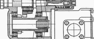
The design is made in a separate cast-iron body with three vertical, through landing channels for the spools and one channel for the bypass valve. The top and bottom of the case are closed with aluminum, one-piece lids. The connecting planes of the covers and the body are sealed with gaskets and tightened with screws.
Hydraulic distributor MTZ 80(82) R75-33R
The distributor has three working lines for the flow of working fluid, located perpendicular to the stroke of switching the position of the spools; discharge line " B" - connects the cavities of the bypass valve and spools, drain line " B" - connects the holes of the spools, the bypass valve control line " G" passes through the distributor body and the holes in the spools, bypass valve 14 is connected to the pipeline. The piston of the bypass valve is equipped throttle jet 13 to create a pressure difference in the discharge channel and sub-piston cavities, which ensures its opening in the neutral position.
The spool valves block and open the working lines with throttling recesses. Control is carried out by levers located in the lower distributor cover. The levers are connected to the spools through a spherical joint 9 with plastic liners 10 and an o-ring 8 . The joint is covered from the outside with a rubber boot 6 . Three spools allow you to simultaneously control three working hydraulic drive units.
Principle of operation
Each spool, depending on the specified position, operates in four modes:
- “ Neutral ” is the average between the uppermost “lifting” and the lower “lowering” position. The bypass valve is open and discharges the working fluid into the drain. The spool valves block all channels, thereby fixing the previously specified position of the hydraulic drive elements.
- “ Rise ” is the first upper position after “neutral”. The bypass valve closes the drain cavity. The spool passes oil from the discharge channel into the cylinder lift line.
- “ Forced lowering ” - the lower position before the extreme “floating” one. The bypass valve closes the drain cavity. The spool passes oil from the discharge channel into the return line of the hydraulic cylinder.
- “ Floating ” is the lowest position of the lever. The bypass valve is open and discharges the working fluid coming from the pump into the drain. In this position, the working fluid flows freely in both directions from both cavities of the hydraulic cylinder. The hydraulic cylinder is in a free position and reacts to external conditions and the machine’s own gravity. Thus, this allows the working bodies of the aggregating machine to follow the terrain when cultivating the soil and maintain stability of the cultivation depth.
Operation of the spool lock
The spools are equipped with a spring-valve mechanism that automatically returns to the neutral position 3 and ball retainers that hold it in the selected position. The automatic return ball valve is activated when the pressure in the system exceeds 12.5-13.5 MPa. Excess pressure occurs when the hydraulic cylinder reaches its extreme position in the corresponding lifting and forced lowering position, as well as when the system is overloaded.
Working equipment
Control channel G is blocked by the cylindrical part of the spool, and the flow of oil through the control channel and the orifice hole of valve 21 stops. Leakage of working fluid Along the spheres of the levers. At the bypass valve guide stop connector.
The rod deflection is allowed no more than 0.1 mm over the entire length. Control channel G is open, since the recesses on the spools between the lower wide flanges are on the axis of channel G. Turn on the stand and use the distributor handle to move the piston of the power cylinder several times, filling both cavities with heated oil.
Due to this, valve 12, compressing spring 13, moves, opening a hole in seat 11, through which oil flows from cavities G and B into the cavity of booster 9, moves it together with retainer 19, releasing the spool. Separate the upper and lower covers, mark and remove the spools from the body, disconnect the safety and bypass valves.
After the oil flow is completely blocked, the pressure gauge reading is noted, which reflects the actual response pressure of the safety valve. Unscrew and remove the safety valve cap, loosen the lock nut and adjust the pressure with the screw.
The body has three through holes for the spools and one for the bypass valve; discharge channel B, connecting the cavities of the bypass valve and all spools; drain channel B connecting the spool holes; control channel G, drilled through all the holes of the spools and bypass valve and connected by pipeline 4 to the regulator pos. Leakage of working fluid occurs due to wear of the gasket or sealing ring of the guide. The highest pressure noted on the pressure gauge at the moment the spool handle returns to the neutral position is taken as the operating pressure of the machine. Why the hydraulics don’t hold the hitch, and why the hydraulics don’t lift
See also: Ignition adjustment MTZ-80 d 240
Why do you need a hydraulic distributor on the MTZ-82 tractor?
Let's take a closer look at the three-section hydraulic distributor R-80-3/1-222G. It is installed in the hydraulic system of the MTZ 80 tractor (being also a basic element when performing modifications of devices used on loaders, excavators and other equipment) to solve the following tasks:
- Protection of hydraulics from overloads during lifting or forced lowering;
- Distribution of oil between hydraulic system elements (cylinders, hydraulic motors, etc.);
- Reduces the load on the system when idling by draining fluid into the tank (“neutral position”);
- Holds the organs of working mechanisms in a certain position.
The marking of the hydraulic distributor contains information about its technical characteristics and parameters. Let's look at how R-80-3/1-222G stands for: the first character indicates that we have a distributor in front of us, the number following it shows the nominal flow rate of the working fluid (in this case it is equal to 80 l/min), followed by the operating code pressure (we have 3, which corresponds to the nominal system pressure of 16 MPa with a maximum of 20 MPa), the unit under the fraction is the purpose code (i.e. the device is designed to work autonomously in general purpose hydraulic systems), 222 - show that in the device has 3 type 2 spools, and the last symbol G indicates the presence of hydraulic locks in the device.
Areas of application
The purpose of using a distributor bypass valve is to control that the operating pressure is within normal limits. If the pressure in a certain area begins to increase and exceeds the specified parameters, part of the medium will be discharged into the bypass circuit.
The pressure regulator is used in the following areas:
- water supply;
- heat supply (working with different sources is allowed);
- cooling;
- conditioning.
The distributor bypass valve is also used in automobile production. It is found in cooling and fuel supply systems. In cars, these devices regulate the air flow of the compressor.
Maintenance
In order for the hydraulic distributor of the MTZ-82 tractor to function without interruption, it is necessary to regularly inspect the component parts and maintain this unit.
Periodic maintenance comes down mainly to checking the oil level in the tractor's hydraulic system. To do this, take the dipstick and lower it into a container with hydraulic fluid. The recommended level should be between the dipstick marks.
In addition, frequent failure of the hydraulic distributor of the MTZ-82 tractor is associated with the use of low-quality oil. Therefore, it is necessary to use only oil recommended by the manufacturer. By regularly checking the condition of the oil line, you can prevent loss of hydraulic fluid.
Hydraulic Maintenance
Maintenance of the system consists of monitoring the level of the working fluid and checking for leaks in all connections, as well as timely cleaning of the filter elements of the hydraulic tank filter.
The oil level should correspond to the position between o and “ O ”. When a tractor is coupled with equipment or machines that have single-acting hydraulic cylinders in their design, the oil level is checked with the cylinders lowered. Otherwise, when the cylinders are lowered, the volume of oil will increase and lead to depressurization or rupture of the tank due to excess liquid.
It is forbidden to turn on the hydraulic pump when the fluid level in the system is below o.
The filter is washed every 500 working hours. When a new tractor is put into operation, the filter is cleaned after the first 60 hours of operation. Dismantling the filter is carried out carefully so that blockages do not get into the hydraulic tank. The filter elements are washed with gasoline or diesel fuel. Also, during maintenance, wash the foam filter element of the breather. Pure, settled oil is poured into the system without foreign solid inclusions, which lead to clogging and rapid wear of hydraulic units. It is also necessary to prevent water from entering the system. Freezing of water at low temperatures clogs the system filter with ice, which leads to rupture of the distributor cap or filter.
The main cause of problems in tractor hydraulics is a clogged distributor. Clogging causes the bypass valve to malfunction and block the working channels of the unit. The general condition and performance of the system and hydraulic units is checked using the KI 5473M diagnostic device. If the pump performance or distributor capacity drops by more than 5 liters per minute, the units are replaced or sent for repair.
Design and principle of operation of the MTZ 82 hydraulic distributor
The main structural elements of the hydraulic distributor are:
- Housing, top and bottom covers;
- Spool control levers installed in the top cover;
- Inlet and outlet channels in the housing for supplying circulating working fluid from the pump to the working cylinders and draining it into the tank;
- Spool valves with locking and automatic return mechanisms;
- Safety valve;
After the MTZ 82 hydraulic distributor is connected to the tractor’s hydraulic system, the movement of oil inside the housing occurs through one of three channels created by the spools and the valve. Let's consider how they are formed and what they serve.
- Discharge channel - passes through all spools and safety valve;
- Drain channel - passes only through the spools, needed to release used oil;
- Control channel - covers the spools and safety valve, while connecting to the line supplying fluid from the pump.
By controlling the spools, it is possible to provide the attachments with different positions by redistributing the hydraulic fluid along the necessary channels. The modes created for mounted units are conventionally divided into four types:
- Neutral position, used when this spool is not used;
- Climb;
- Lowering;
- Floating position, similar to neutral, but at the same time allows the working body to lower under its own weight
This design makes it possible, if desired, to carry out repairs on each individual operating mode and connected circuit of the MTZ hydraulic distributor.
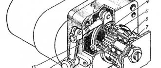
Design of the MTZ-80 hydraulic system: pump diagram
The main “pumping” mechanism of the hydraulics of an agricultural machine is a hydraulic pump. It ensures the operation of all worker nodes.
The design of a hydraulic pump is shown in this diagram.
Through the gear (11), the pump is driven by the main shaft of the tractor power rotation. The device drive is located in the upper part of the intermediate part of the MTZ-80 transmission housing near the clutch housing. The mechanism is started through the control handle (16).
Connection diagram R-80
The P-80 distributor is connected to the hydraulic system of a machine or tractor between the storage tank, pump and cylinders. Depending on the type of hydraulic cylinder used, the connection diagram for the P-80 hydraulic distributor may differ significantly. If the removal of liquid from the cylinder will be carried out under the weight of the attachment, then the fitting going to the cylinder should be connected in such a way that when the spool is opened, its collar opens a channel for draining the liquid into the storage tank. When using a double-sided cylinder, the reverse movement of the hydraulic cylinder rod is carried out by supplying oil from the reverse side of the power mechanism, while the liquid located on the reverse side of the valve must have an open channel for draining the oil into the tank.
Be sure to read: Petrol garden sprayer
Valves classification
Bypass valves differ in different parameters:
- connection method (thread, welding, flange);
- flow direction;
- active element (a diaphragm can be used instead of a shutter);
- mechanism of action (direct action or the presence of additional elements for fine tuning).
The choice of device depends on where it will be used. Requirements vary from system to system; the bypass valve must provide connectivity and the ability to operate under specific operating conditions.
Common hydraulic valve malfunctions and repairs
Most often you may encounter the following problems with the MTZ hydraulic distributor installed on the Belarus tractor:
- Violation as a result of wear of the tightness between the spool and the hydraulic distributor housing;
- Worn hydraulic cylinder piston;
- Destruction of the gear pump;
- The appearance of cracks in rubber seals;
- Violation of the tightness of the connecting fittings;
- Damage to hydraulic system pipelines.
The simple design of the device allows it to be repaired without the participation of service specialists. Often machine operators do it with their own hands. In addition, a special repair kit recommended by the company that produces these products can significantly simplify the repair of the MTZ 82 hydraulic distributor.
The P80 hydraulic distributor, developed many years ago, due to its successful design and high reliability, is successfully used on modern Belarus 920 and MTZ 3022 tractors.
System Maintenance Recommendations
During operation, the technical condition of the hydraulic system and its components should be regularly monitored. At the first signs of wear, the elements are replaced with new ones or repaired. The most common problems include valve failures, deformation of seals and jamming of individual parts of the assembly. In most cases, repairing a structure requires dismantling. Accordingly, the question arises about how to remove the hydraulic distributor on the MTZ 82? Work begins from the cab platform, where the panel with the attachment control system panel is disconnected. Next, the side flap on the hood is removed, the cylinder pipes, distribution fittings and pressure hoses are disconnected. The hydraulic distributor housing itself is removed after unscrewing the bolts from the spar. With the mechanism base disassembled, it is possible to replace individual elements, clean channels with spools, check the condition of oil drains, etc.
Advantages of our store
Our company has formed an experienced and responsible team that has long been familiar with the equipment produced by the Minsk Tractor Plant. Therefore, we can easily select any spare part you need.
In our catalog you will find about 1000 items of spare parts, among them there are both frequently used products and those that are rarely needed. This allows you to find everything you need for repairs in one place.
Understanding that the operation of special equipment involves high loads and difficult conditions, we interact only with trusted manufacturers. This allows us to have no doubt about the high quality of the product and its compliance with the stated technical characteristics.
Source