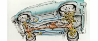
You can already write textbooks about the cross-country ability of the UAZ (Ulyanovsk Automobile Plant) bestsellers. The owners of such cars know very well how this is achieved. For those who are just considering the prospect of purchasing a car of this brand or want to understand the reasons for its vulnerabilities, the first thing to do is to find out about the design of its transfer case.
Transfer case UAZ Bukhanka
The UAZ-452 was originally created for the Soviet armed forces as a medical service vehicle, where it was therefore dubbed the “tablet” (the civilian nickname is “loaf”). Therefore, the design of the mechanisms, including the transfer case, is simplified as much as possible.
During operation, the entire transmission system is unpretentious, which is confirmed by half a century of practice. The only recommendation from the manufacturer is to periodically check the oil level and check the fasteners.
In addition, if necessary, the front linkages should be adjusted and the lever axles should be lubricated on a preventive basis. This mechanical unit, including bearings, does not require any further maintenance or adjustment.
Device and how it works
The transfer case is a mechanism located in a separate housing made of gray cast iron. The assembly is divided vertically into a crankcase and a cover, which are connected by bolts. Both halves undergo joint processing, so it is impossible to install a part from another gearbox. The crankcase has a separate hatch for installing a power take-off. The oil-filled unit with the parking brake drum installed weighs 37 kg.
The transfer gearbox will only work correctly if it is correctly centered on the gearbox housing. For this, a 2-row angular contact bearing and a steel cylindrical cup are used. The gearbox shafts are mounted on ball and roller bearings, secured with nuts and retaining rings, respectively. The output shafts pass through sealing seals installed in the covers.
The drive shaft of the unit is the driven axis of the gearbox, which is equipped with a splined tip on which the gear is located. This part has 2 positions that allow you to get forward and reduced speeds. The shift drive is equipped with a special fuse that prevents the low range from starting until the front wheel drive is connected.
When the gear is connected to the gear wheel of the rear axle drive shaft, direct transmission is ensured. The gearbox device includes a special lever that allows you to move the gear to the side, engaging it with the gear of the intermediate shaft. In this position, the rotation speed of the driveshafts of the axle drives is reduced.
The design of the transfer gearbox has a movable gear wheel mounted on the middle shaft and controlled by a separate lever. This gear provides connection to the front wheel drive. When the gear is disengaged, the gear continues to rotate as it remains in contact with the rear axle drive gear. This operating principle is necessary to spray the oil in the crankcase.
The plant produced several modifications of the transfer gearbox, which differ in the module of installed gears. Because of this, the gear ratio changed - instead of 1.94 it became 1.47. It is possible to remake the old-style transfer case by replacing gears, since the housing design has remained unchanged.
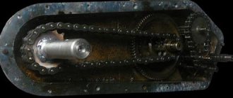
On some cars there is an imported Hyundai Dymos transfer case (Dymos) with electrical control. The unit weighs 32.4 kg, provides direct and low gears (gear ratio 2.542). The unit is equipped with a controller that diagnoses the box and records error codes. The mechanical part of the imported box is very different from the Russian counterpart - instead of gears, a chain drive is used.
Specifications
Briefly commenting on the tabular information, we conclude the following: the “loaf” has two drive axles, the UAZ “loaf” gearbox is of a mechanical type and, together with the transmission, is a monoblock. Activation is carried out using a demultiplier.
Engine UAZ-452
The engine is a modernized GAZ-21 engine installed inside the cabin. This allows you to make minor repairs without leaving the cab. Good load capacity and cross-country ability retain the title of “SUV” and “all-terrain vehicle”. Specifications
| Modification | Glass van UAZ | UAZ bus |
| Body | ||
| Wheel formula | 4x4 | 4x4 |
| Number of seats | 2 or 5 | 9–10 |
| Length, mm | 4390 | 4363 |
| Width, mm | 1940 | 1940 |
| Height, mm | 2064 | 2064 |
| Wheelbase, mm | 2300 | 2300 |
| Ground clearance, mm | 205 | 205 |
| Fording depth, mm | 500 | 500 |
| Curb weight, kg | 1805 for closed van 1920 for glass van | 2005 – for 9 seater bus 2022 – for 10 seater bus |
| Total weight, kg | 2730 for closed van 2845 for glass van | 2880 |
| Load capacity, kg | 925 | 875 – for a 9 seater bus 865 – for a 10 seater bus |
| Engine | ||
| Engine | Gasoline, ZMZ-40911.10 | |
| Fuel | Gasoline with an octane rating of at least 92 | |
| Working volume, l | 2,693 | |
| Maximum power, hp (kW) | 112.2 (82.5) at 4250 rpm | |
| Maximum torque, Nm | 198 at 2500 rpm | |
| Maximum speed, km/h | 127 | |
| Fuel consumption at 60 km/h, l / 100 km | 9,0 | |
| Fuel consumption at 80 km/h, l / 100 km | 11,2 | |
| Fuel tank capacity, l | 77 | |
| Chassis | ||
| Transmission | 5-speed, manual | |
| Transfer case | 2-speed with front axle drive disabling | |
| Brake system | Dual-circuit, with vacuum booster, front disc, rear drum) | |
| Tires | 225/75 R16 |
Safety
When creating the UAZ, the concept of driver safety was considered a secondary task. The main task was to realize the intended purpose. That is, meeting the requirements of the defense field.
According to some experts, this car has a 30 percent chance of surviving a frontal collision.
UAZ Bukhanka front view
Although, crash tests carried out for the first time in 1971 did not confirm this figure. The design does not provide seat belts, but the good news is that in the UAZ “loaf” line, it has decent strength characteristics.
It is also impossible to deny the fact that traffic safety largely depends on the qualities and experience of the driver himself.
Switching transfer case UAZ Hunter
The transfer case is controlled and activated from the driver's cab, remotely. To do this, the user uses the levers located on the right side in relation to him. It is noteworthy that the machine, depending on the installed configuration, uses both single-lever and double-lever gearbox control designs.
The inclusion of a lower gear by an activating mechanism with one lever is accompanied by an independent shift of the lever at the end point, under the influence of a spring element, to the left side (towards the driver).
Transfer case shift lever positions:
The procedure for turning off a lower gear is accompanied by a preliminary shift of the lever to the right until it stops (in the direction of travel of the car). After which the lever moves to the zero position, forward in the direction of movement of the machine.
When working with a mechanism that controls the transfer case with two levers, take into account that the top switch drives the front pair of wheels. Device positions: first (wheel set on), second (wheel set off). The transfer case is controlled by three positions: first (main gear is working), second (zero position), third (low gear is activated).
IMPORTANT!: To prevent breakage of the transfer case gear teeth when switching gears, you can activate and deactivate the device (direct and low gear) only after the machine has completely stopped.
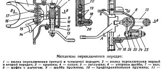
Mechanism adjustment
After assembling and installing the new switching mechanism, it is necessary to adjust the rods and the entire system. The goal is achieved by changing the length of the vertical and horizontal rods. Do-it-yourself setup sequence:
- Move the gear shift lever to the neutral position, and move the element responsible for selecting the gear all the way.
- Move lever 1 to positions corresponding to speeds 1 and 2. While checking that the elements are not pulled up, connect and secure the selection rod.
- Similar actions must be carried out for other gear stages.
After work, you should check that the gears are fully engaged by starting first gear and reverse. The lever must not come into contact with other parts or controls. The optimal gap size is up to 3 mm.
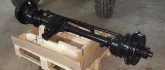
Rear axle drive shaft
What does the UAZ transfer case consist of, what are its features? This shaft is mounted on two ball bearings. To protect the element from axial movements, it is held in place by a rear bearing with a thrust ring and a cover. A gear is attached to the front of the shaft. Its inner crown has slots. The function of this gear is to drive the front drive axle. Internal splines are required to engage direct transmission in the transfer case.
A screw-type gear is also installed on the splines between the bearings. It serves as a drive for the speedometer. The rear part of the shaft is connected to the cardan shaft using a nut with a conical protrusion through a flange. If you tighten this nut, its conical protrusion will bend into one of the grooves that are cut into the threads and stop.
RK Corps
The transfer case housing consists of two parts. To prevent lubricant leakage at the joint, the parts are sealed with gaskets. Oil seals are installed on the shafts coming out of the sealed housing. They prevent lubricant from leaking out when the car is moving.
REFERENCE: Under load, the lubricant and parts of the lubricant heat up. To avoid breaking the seal of the housing, the manufacturer equipped it with a breathing valve. The device provides communication between the device cavity and the atmosphere.
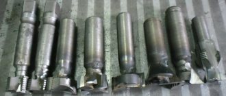
Drive mechanism
The RK mechanism consists of:
- Rear axle shaft. Rigidly connected to the rear driveshaft of the car. Mounted on ball bearings. They allow the shaft to rotate freely;
- Front axle shaft. Drives the front driveshaft. Fastened with a nut;
- Intermediate shaft. Necessary for engaging the front axle or downshifting;
- Shift forks. Used to move gears when turning the front axle on/off and to downshift. The movement of the forks is carried out along specialized rods. Each fork is equipped with a locking mechanism that prevents spontaneous movement of the product along the rod.
Control mechanism
The unit is made in the form of a metal cover. It is bolted to the transfer case housing. Two levers are installed in the cover. One serves to connect the front axle, the second to reduce the torque transmitted from the gearbox.
REFERENCE: The UAZ 469 transfer case diagram shown above is distinguished by its reliability and high service life. With normal maintenance, the unit can be used for a long time, regardless of operating conditions.
Replacing the bearing and oil seal
The design of the transfer case allows the replacement of the rear wheel drive shaft seal without dismantling the unit. To do this, you need to disconnect the driveshaft and remove the parking brake mechanism. The old oil seal is removed using a slotted screwdriver.
Replacing bearings without removing the gearbox is not recommended, since the parts are installed with interference. If the bearings are removed from their housings by hand, the gear housing must be replaced with a new one.
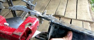
The other day I received a second set of races and washers (according to Tough drawings) for installing a double-row bearing on the front shaft of the RK. In connection with this, the question arose about quickly replacing the bearing without removing the transfer case. The operation is not complicated - but maybe it will help someone not to waste time thinking and running from the pit and back. The tools are standard - heads, wrenches, and preferably a cardan. So:
1. Remove the front cardan, turn on the lock and loosen/unscrew the nut of the front shaft shank.
2. Remove the plastic cover of the control levers in the passenger compartment to gain access to the nuts of the locking lever cover.
3. Disconnect the locking switch sensor and unscrew the four nuts of the locking lever cover. We lift it to make sure that the gasket/sealant does not hold it - it will be inconvenient to tear it out of the hole!
4. Drain the oil from the reservoir into a clean container
Read more: Land Rover Defender 1998
5. Unscrew the nuts securing the front cover of the RC and pull it out from the studs towards you. The shaft with the CV cover passes under the traverse of the third gearbox support, but the locking lever is hidden in the tunnel. As a result, we hold the front cover of the RC with one hand, and with the other we hold the lever so that it does not fall on our heads and carefully carry everything to the workbench/clean floor. ATTENTION – do not lose the spring and ball of the locking rod retainer!
6. Next, we change the bearing (I won’t describe the process - everything is done as in the manual) with a new one or with a cage - my case.
Now all this needs to be installed back. To do this, you need to remove the locking lever and assemble everything without it:
7. Use a screwdriver to pry up the washer holding the axis of the locking lever and remove/knock out this very axis (it comes out with difficulty).
8. We wipe everything with a rag soaked in kerosene/diesel oil and make sure that the axle enters/exits freely - by hand - if not, then you need to do this - neither a hammer nor a pry bar can help.
9. Next, carefully apply the sealant (before this, be sure to remove traces of the old one) onto the cover of the locking lever and install it in place (without the lever).
10. We put the RC in neutral, and turn on the lock on the front cover of the RC so that the clutch does not fall out. We climb into the hole with the assembled RC cover and, having applied sealant to it, put it in place; for me it stopped 5 mm to the end and refused to go any further. I put the front flange on the shaft and rotating the rear and front flanges squeezed them towards each other - click - the cover sat down! The flange can be removed - without it it is more convenient to install the lever.
11. Tighten the front cover nuts.
12. Install the lever (not forgetting about the axle lock washer and the metal gasket between the lever and the locking rod - it probably serves to dampen vibrations from the rod to the lever).
13. Next, we reconnect the lock activation sensor and turn on the lock.
14. We put on the flange and tighten the nut with the proper torque.
15. Well, then - we install the cardan, the lever casing - we check EVERYTHING! - ATTENTION! Don't forget to refill the oil!
PS If I missed something, don’t be angry – I’m not particularly good at writing, but I think I didn’t forget to point out anything fatal.
Causes and troubleshooting
The design of the UAZ gearbox is reliable, trouble-free and durable. However, problems with equipment occur due to errors in use and violation of established regulations.
| Source and symptoms | What to do |
| Exceeding the permissible hum level of a working device | |
| Erasing the gear teeth of the box. | Replace worn out box items. |
| Weak fastening of the transfer case to the box, or reduced fixation of the bearing caps. | Tighten the fasteners, if the symptom recurs, dismantle the product and eliminate the defect. |
| Bearings are worn out. | Replace erased items. |
| Saturation of the working fluid with wear products from the box. | Remove the pan, wash it, change the oil. |
| Incorrect oil used, low fluid filling level. | Change the working fluid, set the desired level. |
| Carrying out repairs to replace gears, without selecting a product to minimize noise. | Check the gears for noise and replace them with the required ones. |
| Switching steps is difficult | |
| Different wheel wear. | Replace with wheels with the same tread and equalize the internal pressure. |
| The joints of the longitudinal projections of the main and the mediator shaft are jammed. | Sand the areas with burrs; if that doesn’t help, change the elements. |
| The drive gear has damage on the teeth of the small ring. The shift fork rod is bent. | Sand the damaged areas, straighten the rod, if that doesn’t help, change the element. |
| The switch rods are stuck on the axle. | Separate the parts, clean the axles and pipes, coat with lubricant, and connect the product again. |
| Spontaneous speed shutdown | |
| Erasing the teeth of the gears of the box. | Replace worn out box items. |
| The box bearings are worn out. | Replace worn box elements. |
| A large gap in the articulation of the shaft and gear. | Select the gear according to the size of the longitudinal protrusions. |
| The transmission is unable to engage because the mechanism is bent or there is damage to the gears and cylinders. | Correct bends, sand damage, or replace parts. |
| Poor functioning of the locking mechanism, loss of elasticity of the spring mechanism, abrasion. | Replace erased items. |
| Leakage of working fluid | |
| Violation of the integrity of the sealing elements of the pan, bearing caps, and the transfer case’s articulation with the gearbox. | Replace sealing elements. |
| Weak fastening of the cover, bearing, pan, joints. | Tighten connections. |
| Violation of the integrity of the shaft seals. | Replace the damaged element. |
| Violation of the integrity of the tray or lid. | Replace the damaged element. |
| The plugs of the switching rods, switching rods, and the plugs of the front bearing of the middle shaft fall out or are broken. | Change the plugs. |
| Bearings are damaged | |
| No, or a small amount of lubricant. | Change or add fluid. |
| Demolition of cages and bearing rings due to abrasive. | Change the elements, dismantle and wash the pan, change the working fluid. |
| Excessive shaft bearing friction. | Disconnect the element, clean the product, and coat it with lubricant before reassembling. |
Transfer case maintenance
With constant use of the vehicle, the transfer case of the UAZ “Patriot” and any other model requires careful maintenance.
The standard part care process includes:
- visual inspection for the presence of lubricant leaks in places where rubber seals and gaskets are located;
- checking the fasteners that attach the gearbox to the gearbox and tightening the propeller shaft bolts;
- Changing the oil in the UAZ transfer case.
Car maintenance requires simultaneously changing the oil in the gearbox and transfer case of the UAZ Patriot. The frequency of replacement is determined independently, taking into account the manufacturer’s recommendations. Regardless of which transfer case is installed on the UAZ, the Ulyanovsk Automobile Plant recommends changing the oil every 35-40 thousand kilometers.
When regularly operating a vehicle in off-road conditions, the oil must be changed more often, since the transfer case and the entire transmission of such a vehicle are subject to increased loads.
Without careful maintenance and care, the transfer case may fail, after which the driver will have to replace the UAZ RK with a new one.
Checking handouts
The advantage of a torque impulse distributing device is that the device requires minimal intervention and maintenance. Manipulation consists of checking the level and changing the oil, inspecting the joints for damage. Before working with the box, the product is cleaned. This helps detect hidden cracks and leaks. If such symptoms are found, they find out the cause of this phenomenon. Defective parts are usually replaced, such as seals and seals.
After cleaning and visually inspecting the dispenser surface, check the product's lubricant level. If there is not enough liquid, add substance. At the same time, check the oil in the gearbox; the value corresponds to the lower edge of the filler hole. If the fluid level in the transfer case is low, but at the same time high in the transmission, there is no need to add it, since the total amount of fluid has not changed.
A detailed inspection of the box includes disassembling the product. After washing and air drying, the area is checked. The pan and plugs are checked for cracks and chips. Seals and gaskets have been replaced with new ones.
Changing the oil in the UAZ gearbox:
They check whether the condition of the working parts on the shafts and grooves is normal, so that the teeth of the gears do not wear out or become scratched. Even if the damage is minor, the products must be replaced. Attention is paid to the bearings; abrasion of the ring tracks is not allowed. Cages, spheres, rollers, etc. are also checked. Gaps, fragments, impacts, uneven movement are a signal to change the product.
READ Rear lights of VAZ 2107 do not light up
Cranks and forks become stuck and deformed, spring elements lose elasticity, and products change. In addition, you should carefully consider the issue of switching when finding the UAZ levers and handouts. The clutch teeth are checked for damage. The weak link of the differential is the satellite. Small defects force the product to be ground or, in the worst case, changed.
general information
First, let's figure out what this part is and why it is needed? The transfer case is a unit that is responsible for distributing torque from the car’s engine to multiple drive mechanisms, and they quite often increase the number of gears in the transmission.
Some cars of this brand are equipped with an improved small-module box. In such a box, the teeth of the gears of the front and rear axles, the teeth of the rims of the drive rollers of the front and rear axles are made with a module of 2.5 mm (in other transfer cases - 3.5 mm). The transfer cases can be replaced with each other, and in addition, they are exactly the same in appearance.
Maintenance
Like any other car part, the transfer case also requires some maintenance. So, the necessary maintenance:
Check the oil level regularly to ensure timely replacement.
Please note that during vehicle operation, the oil level in the gearbox may drop by up to 8 mm relative to the lower edge of the filler hole, as well as its increase. In this case, there is no need to equalize the oil level, because the total volume of oil contributes to the normal functioning of both units. Check all fastenings regularly; In case of oil leakage, it is necessary to detect and eliminate the cause, namely, replace failed cuffs, plugs, gaskets, etc.;
Removing and disassembling the transfer case
Removing the transfer case
We work together on an inspection ditch or lift.
Drain the oil from the transfer case (see Changing the oil).
Remove the left and right floor linings (see Removing the parking brake drive mechanism). Disconnect the speedometer drive from the transfer case (see Replacing the speedometer drive). Remove the front and rear driveshafts (see Removing the driveshaft).
Using a 13mm wrench, unscrew the two nuts securing the exhaust pipe clamp to the gearbox bracket.
Using a 12mm wrench, unscrew the two bracket mounting bolts...
Disconnect the wire ends from the parking brake warning switch.
Using two 19mm wrenches, loosen the tightening of the switch adjusting nuts.
Remove the rubber buffer of the switch.
Unscrew the nut and remove the switch.
We disconnect the adjusting fork from the parking brake lever and, having unscrewed two bolts, remove the brake lever along with the rods (see Removing the parking brake drive mechanism).
Holding the eight crossmember mounting bolts with a “17” wrench, unscrew their nuts with a “19” head.
Using a 17mm wrench, unscrew the two bolts securing the transfer case to the gearbox on the right side...
...and with a 19mm wrench, use the two nuts on the left side.
Tapping with a hammer through a wooden block..
...and, pressing with a mounting spatula, remove the transfer case.
Remove the spacer washer.
Install the transfer case in reverse order:
We replace the sealing gasket between the transfer case and the gearbox, applying a layer of sealant to the gasket. We engage direct transmission in the transfer case with a lever, guiding the drive gear by hand through the hole in the crankcase. For ease of installation:
Using a 12mm wrench, unscrew the four bolts securing the switching mechanism.
Install the intermediate washer. We use sealant to “glue” the sealing gasket to the gearbox. By turning the parking brake drum, we put the transfer case on the studs and the secondary shaft of the gearbox. We tighten the bolts and nuts securing the transfer case. By evenly tightening the bolts and nuts, we ensure that the outer ring of the bearing is pressed into the transfer case socket and that the units fit tightly together. Install the removed parts in reverse order.
Pour transmission oil into the transfer case (see Changing the oil).
Disassembling the transfer case
We remove the transfer case (see Removing the transfer case), clean it from the outside of dirt and place it on a workbench. Pour about 0.5 liters of kerosene or diesel fuel into the crankcase and rinse the box, intensively rotating the shafts. Drain the liquid. Remove the speedometer drive (see Replacing the speedometer drive).
Repairing transfer case: do-it-yourself UAZ car
The transfer case helps distribute the torque from the engine to several drives at the same time.
You can repair the UAZ transfer case yourself; it is not as difficult as it seems at first glance, and you will also be able to save on paying for the services of a car service technician.
Causes of transfer case malfunction
This is the unit
Before starting repairs, of course, it is necessary to find out the cause of the malfunction.
- There was a loud noise in the transfer case. This could be the result of loose nuts that connect the transfer case to the transmission or loose bolts on the bearing caps. The list of reasons includes wear of the bearings or gears themselves, poor-quality or unsuitable oil, or its low level.
- Gear selection and shifting work poorly. This usually occurs due to the clutch seizing on the splines of the front drive hub or shafts. Or, alternatively, the gear selector is deformed.
- The transmission switches off spontaneously while the vehicle is moving. The gear teeth may be worn. Also, shutdown may be affected by an increase in the gap in the spline connection or wear of the clamp parts.
- Oil leaks. Often the problem is caused by wear or mechanical damage to the sealing gaskets, loosening of the nuts on the cover, wear of the seals or sealing rings of the actuator rods.
The solution to all these problems is either repair or replacement of faulty parts. In some cases, it will be enough to just tighten the nuts or add oil.
Stages and main points of repair
Repair of the transfer case takes place in several stages.
- Removing and disassembling the box.
- Troubleshooting.
- Eliminate these faults by replacing the part or repairing it.
- Assembling and installing the box in place.
To remove the box and disassemble the UAZ 469 transfer case, you need to proceed as follows:
- drive the car into the inspection hole;
- lower the parking brake lever and put the gear levers and transfer case in neutral;
- then the casing and lining are unscrewed one by one, the handles and covers are removed, and all wires are disconnected.
Before you start disassembling the device, you need to wash it and drain all the oil. For ease of disassembly, it is better to use a special stand where the transfer case can be secured.
When disassembling the differential, it is advisable to mark on its body the relative positions of the driven gear mounting bolts, so that later it will be easier to put everything back in place.
Finding faulty parts, repairing and replacing them
Before inspection, all parts must be cleaned with a brush and rinsed.
- Oil seals. They are considered unusable if the wear of their working edge exceeds 1 mm. For any minor damage, the part is replaced with a new one.
- Covers and crankcase. Cracks, dents, chips - all this is a good reason to replace it with new parts. However, for very minor damage, you can get by with simply cleaning the damaged area with a file.
- Gears. Worn teeth and their chipping are a reason to replace the part. Otherwise, this will lead to deterioration in handling on difficult road sections and increased load on the engine.
- Shafts. For these devices, the first thing to check for wear is the splines, working surface and threads. By installing the front and rear drive shafts on the prisms and turning them by hand, as well as the drive shaft, we check the runout of the end part, which should not exceed a tenth of a millimeter.
- Bearings. Check for scratches and other damage to the surface. Any cracks or chips indicate the need to replace the bearing. The work of the part must be flawless. It is important that its turns are carried out without jamming or extraneous sounds. Otherwise, the bearing is unusable and must be replaced.
- Clutch and hub. May have nicks, burrs and burrs, which can only be cleaned with a file. If the ends of the teeth on the coupling are damaged or deformed, the part must be replaced.
- Differential. In case of minor damage to the surface of the satellite axis, they can be sanded with fine-grained sandpaper. If the damage is significant, the axle will have to be replaced.
The UAZ transfer case is assembled in the reverse order to the one in which it was disassembled, and before installing the unit in place, its operation is checked on the stand. The function must be flawless, the assembly must be correct, and it is important that no oil leaks. Tests are carried out first in a higher gear, then in a lower gear.
General characteristics
UAZ gearbox
A gearbox is a car's gearbox. The UAZ 469 has a manual 4-speed gearbox equipped with inertia-type synchronizers. They are designed to engage gears without noise or rumble. Synchronizers help equalize the speed of the connecting teeth before engaging. The rotation speeds of the motor and wheels do not match; a synchronizer is needed to combine them. In addition, the gearbox allows the car to move in reverse.
The UAZ 469 gearbox consists of the following parts:
- input shaft;
- front cover;
- special purpose nut;
- auxiliary fasteners;
- auto laying;
- ball bearings;
- secondary shaft drive bearing;
- crankcase;
- coupling for connecting III and IV gears;
- 3rd gear gear;
- 2nd gear gear;
- clutch for connecting 1st and 2nd gears;
- 1st gear gear;
- secondary shaft;
- fastening washer;
- gearbox spacer ring;
- mounting bolt;
- washer for fastening;
- intermediate shaft;
- reverse gear axis;
- reverse gear;
- cork;
- block of gear wheels driving the intermediate shaft and 3rd gear;
- lid.
The device of the UAZ box
If you are interested in the UAZ gearbox diagram, it is easy to find it in photos and drawings posted on various sites on the Internet.
4 studs are screwed into the clutch housing, on which the gearbox is attached. The intermediate shaft drive has gears that are in stable mesh. 1st gear gears have straight teeth, 2nd and 3rd gears have spiral teeth. They are mounted on the drive shaft, supported by needle bearings. The drive shaft has 2 supports. When engaging second gear, the role of the clutch is performed by the first gear. Activation of reverse and first gear occurs due to the movement of gears. Gearbox ball bearings. To prevent movement along the axis, the gears are secured with rear bearings. The rear bearing of the intermediate shaft is integrated with the shaft itself using a bolt.
The switching device has 3 forks attached to the rods with locking screws and located in the side cover. The ball-shaped stopper for neutral position and engaged gears has a rod. The locking blocks located between the rods do not allow connecting 2 gears at the same time. The support contains a lever that helps move the forks. It itself is pressed by a spring to the supporting spherical surface. The boot placed on the lever prevents water and dirt from entering the device. To prevent accidental engagement of reverse gear (the driver may simply get confused), this device contains a fuse - a plunger, which is equipped with a return spring and a ball.
The box lubrication device is combined with the transfer case. Lubricant from the transfer case passes into the UAZ gearbox through a double-row bearing (angular contact) and the existing drain device, after which it returns through the drain hole.
UAZ gearbox repair
The manual gearbox is the most important transmission unit of the UAZ 469 vehicle. The UAZ 469 gearbox has a responsible and fundamental task - monitoring the variability of the engine torque and carrying out transmission from the engine to the driving wheels of the vehicle. The UAZ 469 manual transmission has a fairly long service life. This does not mean that the gearbox does not need repair.
Site about off-road vehicles, SUVs, off-road vehicles
The transfer case of utility vehicles of the UAZ-452 family is designed to distribute torque between the vehicle's drive axles. In addition, the transfer case has an additional reduction gear, which allows you to significantly increase traction on the wheels in difficult road conditions.
Main technical characteristics of the UAZ-452 transfer case.
— Center-to-center distance in mm: total — 213.5 1st pair of gears — 106.75 — Maximum input torque, kgcm: 89 — Gear ratios: highest gear — 1st low gear — 1.94 — Gear module, mm: 3.5 — Splines of the drive axle drive output shafts: number of splines — 10 outer diameter, mm — 30-0.02, 30-0.04 inner diameter, mm — 23-0.21 spline width, mm — 4.5-0.011, 4.5-0.061 — Transfer case weight boxes, kg: 29.7 - Crankcase filling capacity in l: 0.7
Transfer case for cars of the UAZ-452 family.
The transfer case has drive axle drive shafts, an intermediate shaft and five gears. All mechanisms are enclosed in a cast-iron crankcase with a connector perpendicular to the axes of the shafts. The main number of parts are connected to the crankcase cover, so during assembly they are clearly visible and conveniently mounted.
The box has such a kinematic scheme in which the gears come into operation only when the front axle is turned on. When one rear axle is engaged, torque from the drive shaft is transmitted to the rear axle drive shaft. The drive shaft is the rear end of the gearbox output shaft.
The rear axle drive shaft is mounted on two ball bearings. The shaft is held against axial movement by the rear bearing using a thrust ring and a cover. In the front part, the shaft has a gear and an internal ring with involute splines. The gear serves to drive the front axle, and the inner ring serves to engage direct transmission in the transfer case.
A helical gear for the speedometer drive is installed between the bearings on the splines. At the rear end of the shaft, a flange for connection to the propeller shaft is secured with a nut having a conical protrusion at the outer end. After tightening, the conical protrusion of the nut is bent into one of the two grooves on the shaft thread and locked.
The intermediate shaft is mounted on two bearings. The front bearing is a radial roller bearing. The outer race with rollers is pressed into the housing and closed with a plug, the inner race is pressed onto the shaft. The rear bearing is a radial ball bearing, secured to the shaft with a nut and has a thrust ring for fixing the bearing and shaft in the housing. The outside of the bearing is covered with a cover. The shaft is made as one piece with the reduction gear; in addition, it has involute splines for fitting the front axle engagement gear.
Safety precautions when performing work
When repairing the transfer case on a UAZ 469, or performing unit maintenance operations, you should work with gloves and safety glasses. It is advisable that the car owner does not work on the car alone. A partner should always be nearby. When operating a power tool, you must ensure that it is in good condition. All devices, machines, tools must be reliably grounded.
The article introduces readers to the purpose, design, operating principle, and frequency of maintenance of the transfer case of a UAZ 469 vehicle. The author will be glad if recommendations, visual materials and advice help the owners of this model to promptly identify all faults and eliminate them. Our recommendations are aimed at extending the service life of the machine, maintaining its reliability, durability, and high technical indicators laid down by the manufacturer.
How to disassemble and reassemble
Algorithm for removing the unit from the car:
- Disconnect the propeller shaft flanges from the transfer gearbox.
- Unscrew the attachment points of the transfer case to the gearbox.
- Separate the units by simultaneously removing the locking ring located on the intermediate shaft of the gearbox.
- Remove the gaskets from the mating surfaces.
- Remove the cover of the opening for installing the power take-off gearbox, and then dismantle the gear selection mechanism (together with rods and levers).
- Remove the handbrake drum secured with several screws. After this, you need to remove the rear propeller shaft drive flange.
- Remove the bolts securing the parking brake mechanism to the transfer gear housing. After this, you need to remove the mechanism.
- Remove the flange for installing the front axle drive shaft. Then you need to unscrew the front bearing cap.
- Remove the bolts connecting the crankcase halves. Disconnect the assembly, keeping all internal elements on the cover. It is not recommended to remove the covers and steel bearing cup.
- Disconnect the shift rod stopper and remove the elements using a soft hammer. At the same time, the shift forks are dismantled along with the clamps.
- Unscrew the speedometer drive gear lock.
- Using a screwdriver, remove the bearing retaining rings and then remove the transfer gear shafts.
- Remove the bearings from the shafts using a puller.
- Press out the drive shaft of the rear wheels, remove the oil deflector and the speedometer gear drive. After this, you need to remove the bearing with a puller.
- Disassemble the gear shift mechanism (if necessary).
- Carry out troubleshooting of parts, replace worn elements with new ones. If the housing is damaged, the transfer case must be replaced with a new one.
- Assembly of the unit is carried out in reverse order. It is necessary to install new original gaskets; the use of parts with increased thickness is prohibited.
Read more: Gazelle 406 tachometer does not work
It is recommended to disassemble the imported Daimos box in a car service center, since repairs require special equipment. The unit is equipped with electric drives, so it is difficult to adjust the mechanism yourself.