Did you like the article? Follow our channel for new ideas of useful car tips. Subscribe to us in Yandex.Zen. Subscribe.
After restyling in 2003 and 2010, the popular truck in Russia received a new name - Gazelle-Business. But the car received not only a name prefix and modified upholstery - more than 20 components were revised and in total the automaker made 130 design changes, including a modified electrical circuit.
If we compare the first-born, released in 1994, and the new product, the alterations turned out to be significant. The service experience accumulated over the years allowed us to formulate tasks for designers and engineers, which were implemented in the new model.
GAZ Gazelle business 4x4 Titan - pinout
1 - not connected 2 - 382.3801 has an open door alarm (may not be present). You can run a wire to the limit switch on the driver's door. 3 - 382.3801 has an oil overheating indicator (may not be present). You can run a wire to the TM-108 overheating sensor, and put the sensor itself into the crankcase. 4 - 385.3801 has an open door alarm (may not have one). You can run a wire to the limit switch on the driver's door. 5 - 382.3801 has a test. If ground is applied to this contact, the indicators for brake fluid level, oil overheating, open doors and coolant overheating light up. Can be connected to a button or relay. In the second case, the relay winding is connected to ground and the wire from the lock to the starter (i.e., when the starter is turned on, the lamps will be tested). 6 - 382.3801 has a seat belt warning indicator (may not be present). 7 - 382.3801 has a fuel reserve indicator. Connect the blue wire with the red stripe. 8 — fuel level indicator. Connect to the pink wire with the red stripe. 9 — oil pressure indicator. At 382.3801, run a wire to the sensor (you need a VAZ-2106 tee) from GAZ under the ZMZ-406 engine. With 385.3801, if you install a sensor, it will squeak about low pressure at idle, so a sensor is not needed, you need to connect the wire from the device to ground through a resistor, select it experimentally. 10 — emergency oil pressure indicator. Connect to the gray wire with a blue stripe. 11 — engine overheat indicator. Can be connected to overheat sensor TM-111-02. The sensor itself must be in contact with the coolant. 12 — coolant temperature indicator. Connect to the green wire with a white stripe. The pointer will exaggerate the readings; you can connect a resistor to the wire gap and select it experimentally. 13 - indicator for closing the carburetor air damper. Connect to the gray wire with an orange stripe if the car is a carb. 14 - for 382.3801 the indicator may be on and will light up when the mass is supplied. 15 - downshift indicator (may not be present), will light up when the mass is supplied. 16 - differential lock indicator (may not be present), will light up when the mass is supplied. 17 - for 382.3801, the seat heating indicator will light up when positive is applied. 18 - rear PTF indicator (may not be present), lights up when positive is applied. 19 — side light indicator. Connect to the yellow wire. 20 — instrument lighting lamps. Connect to the white wire. 21 - 385.3801 has power supply to the meter. Connect to constant power (red-white wire of stop switch). 22 and 23 - right and left turn signal indicators, respectively. You can connect them together and connect to a blue wire with a white stripe (the arrows will light up when the left or right turn signal is turned on), or to the hazard warning switch: blue - right, blue-black - left, insulate the blue wire with a white stripe (each arrow will correspond to the activation of its turn signal). 24 - parking brake indicator. Connect to the brown wire. 25 - high beam headlight indicator. Connect to the green wire with a black stripe. 26 - front PTF indicator (may not be present), lights up when positive is applied. 27 - ABS indicator. When the mass is supplied it will light up. 28 - 385.3801 has a rear window heating indicator. Lights up when positive is applied. 29 — speed signal output to the on-board computer. If it is, then take the speed signal from this contact. 30 - to the vehicle speed sensor. 31 - low brake fluid level indicator. Connect to the pink wire with a blue stripe that goes to the lamp above the cigarette lighter. 32 - power supply for lamps and devices. Connect to the orange wire with the blue stripe. 33 - battery charge indicator. Connect to the brown wire with a white stripe. 34 - mass. Connect to the black wire. Wow, I wrote a lot... 35 — speedometer power supply. Connect to the orange wire. 36 — speedometer mass. Connect to the white wire with a black stripe. 37 - tachometer. Connect to the brown wire with a blue stripe, but if the readings drop, connect to pin 38. 39 - 385.3801 has a low beam indicator (it may not be present), it will light up when positive is applied. 40 - low oil level indicator (may not be present), will light up when the mass is supplied. 41 - if the car is injection, connect to the orange wire too. 42 - if the car is injection, connect to the remaining wire (I don’t know the color) it went to the 8-terminal block on the old device. 43 - brake pad wear indicator (may not be present), will light up when the mass is supplied. 44 - glow plug indicator. 45 and 46 - does not connect. 47 - low coolant level indicator (may not be present), will light up when the mass is supplied. 48 - low washer fluid level indicator (may not be present), will light up when mass is supplied. 49 - low power steering oil level indicator (may not be present), will light up when the mass is supplied. 50 - the indicator for burnt out lamps on 382.3801 or the presence of water in the fuel filter on 385.3801 (may not be present) will light up when the mass is supplied. 51 and 52 - 382.3801 has indicators (may not be present) that will light up when the mass is supplied.
Purpose of elements on the GAZ instrument panel
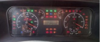
1 — the voltmeter indicates the voltage in the on-board network of the GAZ car; 2 — warning lamp of the engine management system; 3 - reserve (or abs malfunction warning lamp on a Volga GAZ car equipped with an anti-lock brake system); 4 — “STOP” light display. Lights up simultaneously with one of the malfunction indicator lamps, if further movement with this malfunction is prohibited; 5 - indicator lamp for turning on the left turn signal. The lamp lights up simultaneously with the left turn indicators. If one of the indicator lamps malfunctions, the control lamp blinks at double frequency; 6 - warning lamp for emergency drop in brake fluid level. The lamp lights up when the fluid level drops (below the minimum allowable) in the brake master cylinder reservoir. As the brake pad linings wear, it is necessary to add brake fluid; 7 — odometer (total mileage counter); 8 — the speedometer indicates the speed of the car; 9 - indicator lamp for turning on the parking brake. The lamp lights up when the parking brake lever is raised and the ignition is on. 10 — control lamp for turning on the right turn signal. The lamp lights up simultaneously with the right turn indicators. If one of the indicator lamps malfunctions, the control lamp blinks at double frequency; 11 - reserve; 12— warning lamp for unfastened seat belts (installed on some Volga GAZ 31105 cars); 13 or 18 - warning lamp for emergency drop in oil pressure in the engine lubrication system. The lamp should light up when the ignition is turned on and go out after starting the engine. If the light remains on after the engine has started, or comes on while the engine is running, stop the engine immediately and check the oil level. The level is normal - the engine is faulty. For a car with high mileage, the lamp may come on when the warm engine is idling; 14 — reserve (for installing additional warning lamps); 15 — fuel level indicator. The device shows the approximate amount of fuel in the tank. The scale has divisions: 0 - empty tank; 1/2 - half a tank; 1 - full tank: 16 - fuel reserve warning lamp. The lamp turns on when the remaining fuel in the tank is less than 8 liters; 17 — oil pressure indicator in the engine lubrication system allows you to assess the technical condition of the engine; 19 — control lamp for turning on heated seats (for GAZ 31105 vehicles with heated seats); 20 — coolant temperature gauge allows you to control the engine temperature; 21 — control lamp for turning on external lighting (side light); 22 - the coolant overheating warning lamp turns on when the coolant temperature rises above the permissible value; 23 - control lamp for turning on the high beam headlights. The lamp turns on when the high beam headlights are turned on; 24 — button for setting the daily mileage counter to zero. In order to reset the counter readings, you must press the button; 25 — car daily mileage counter. To reset the counter readings, you must press the zero setting button (pos. 24); 26 - tachometer. The device shows the engine speed; 27 - battery discharge warning lamp. The lamp should light up when the ignition is on, and go out after starting the engine. Illumination of the lamp while the engine is running may indicate a malfunction of the generator or its circuits.
Detailed description of icons
Details about instrument combinations, decoding of symbols and pictograms are described in the GAZelle operating instructions.
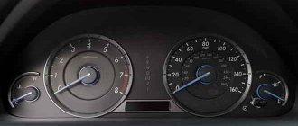
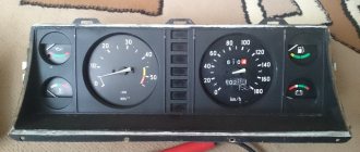
The panel is a combination of instruments with sound and signal indication. The main meters that the driver focuses on are the speedometer and tachometer, located on either side of the signal sensors. The speedometer indicates the speed of the vehicle. Its scale ranges from 0 to 200 km/h. The tachometer shows the crankshaft rotation speed of the power unit per minute with a scale of 0-6.
On the left side of the speedometer there is a device that determines the amount of fuel in the fuel tank. Nearby is the “Reset” button, when clicked, the daily mileage readings are reset to zero. Mileage parameters can be read on the digital odometer, with the upper numbers indicating the total value, the lower ones indicating the daily value.
To the right of the tachometer is the coolant temperature indicator. The arrow moving into the red sector means the engine is overheating. The motor runs until the alarm high temperature signal is triggered.
In the lower right corner there is a “Mode” button that turns on the ignition. Signal sensors are installed in the center of the panel.
Flashing red:
- STOP indicator, when activated, further movement is prohibited until the problems in the car are resolved;
- indicator of lack of battery charging, which operates when the ignition is turned on until the engine starts;
- indicator of low oil pressure in the engine;
- minimum fluid level sensor in the brake system hydraulic drive reservoir;
- engaging the parking brake.
The following are lit in green:
- left and right direction indicators;
- side light switch;
- Low beam headlight switch indicator.
Sensors flashing orange are responsible for turning on the rear fog lights, as well as for malfunctions of the anti-lock braking system and engine control mechanism. The high beam switch is blue.
In addition to the color display, an audible warning in the form of a characteristic signal has been developed on the instrument panel. It occurs in the following cases:
- when the fuel level drops to a minimum;
- when the engine temperature rises to 105° or more;
- when the handbrake is released and the car is moving at a speed of 2 km/h.
The disadvantage of the new panel is that it is difficult to install. The problem is solved this way: the pinout diagram is included in the package, you just need to add a few terminals, change the contacts so that all systems and components work correctly, connect LED lighting inside the devices and around the perimeter of the panel for better visualization.
Replacing the old instrument cluster with a new one
Many car owners of a gazelle or Volga car with an old-style instrument panel strive to change it to a new-style instrument panel, in which most of the indicators have been replaced with modern LED ones, and such an instrument panel looks much prettier and brighter.
So, to remove the instrument cluster, first remove the trim by unscrewing the four screws. Then remove the four screws securing the combination; disconnect the electrical connectors and remove the instrument cluster. Repair the instrument cluster by block replacement of faulty devices. To replace devices, remove the protective glass and unscrew the nuts securing the faulty device on the reverse side.
The reason why many drivers install the Gazelle Business dashboard is because it looks better. The second reason why you should buy this particular panel option is the functionality and increased number of opportunities to monitor the performance of the car.
The euro-type panel has 2 large dials - speedometer and tachometer, as well as 2 small ones, which display the amount of gasoline and the temperature of the coolant. The rest of the information about the state of the nodes and any errors that have occurred is displayed using illuminated indicators in the middle of the panel. A simpler design significantly relieves the driver’s attention.
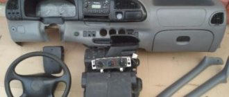
Installing and removing the torpedo
The instrument panel is only part of the euro kit for the Gazelle business.
Gazelle instrument panel lighting
In some cases, for example, to repair the heating system, it is necessary to completely dismantle the torpedo. This process is not the easiest, since you need to know from which side to approach such an issue.
In fact, the panel can be removed in just half an hour. To do this you need the following:
- Use a Phillips screwdriver to unscrew the 3 upholstery fasteners.
- Carefully remove all upholstery pads so as not to damage anything.
- We dismantle the steering column with all connections to it.
- We remove the instrument panel by disconnecting all wires.
- Next you will need to turn off the interior lighting and rear fog lights. Then we turn off the electric headlight adjustment.
- We arm ourselves with keys 7 and 8, get to the bolted fastening of the choke cable. Hold it with one key and unscrew it with the other.
- We unscrew the screw of the cable sheath and disconnect the cable from the Gazelle carburetor.
- We turn off the hazard warning lights and cigarette lighter plugs.
- Again, take a screwdriver and tighten 2 screws near the stove control.
- We unscrew all the screw fastenings of the panel, there are 10 of them in total. Lightly pull the panel towards you so that it comes off the installation site. Now you can disconnect the air duct hoses from the deflectors.
- We take out the damper from the carburetor. We remove the panel. We turn off the right and left air ducts of the stove.
- We remove the torpedo. You will need an assistant here, since the torpedo is very heavy.
- We twist the fastenings of the torpedo lining and remove the lining itself.
- Installation is carried out in reverse order.
The dashboard sparkles with numerous lights, arrows and indicators, which can make a person who sees all this beauty for the first time confused. Meanwhile, it is necessary to navigate the indicators and their purpose, because they inform the driver about the state of the car and its main systems. In this article we will talk about what information can be gleaned from the fact that certain lights on the instrument panel are on or off. All dashboard indicators are divided into three groups: Red. These are warning lights that indicate malfunctions in the system, which can lead to big troubles. Yellow. These indicators usually perform an informational function. There are exceptions, which relate, for example, to the inclusion of all-wheel drive. All the rest are blue, purple, green, etc.
Instrument cluster 3110.3801000-90 for GAZ vehicles. Pinout.
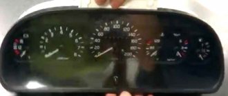
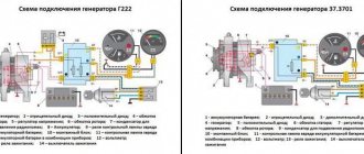
Many car owners of a gazelle or Volga car with an old-style instrument panel strive to replace it with a new-style instrument panel, in which most of the indicators have been replaced with modern LED ones, and such an instrument panel looks much more attractive and brighter. But there’s just one problem: you won’t be able to change the instrument panel one-on-one. Either half of the indicators will not light up, or, on the contrary, extra indicators will light up. Let's figure out how to install a new type of instrument cluster (panel) 385.3801-10 instead of the old panel with light bulbs 384.3801-10, which has served for many years. To begin with, let us present to your attention a combination of instruments of the old and new models.
In our case, we changed the instrument cluster on a Gazelle car with a ZMZ 405 Euro-2 engine and a Mikas 11 control unit. If you just take and install the instrument cluster without modifying the wiring, then our combination will work halfway. What will not work or work incorrectly:
CHECK ENGINE indicator will not work (the indicator does not light up when the ignition is turned on) – Instrument cluster backlight does not work – LCD indicators do not function – EBD indicator lights up – ABS indicator lights up – Low beam indicator does not light up when it is turned on
Why is this so, you ask. It’s just that the wiring connectors do not have the necessary contacts for the combination to work properly. Let's look in more detail at what contacts we need are missing, but first, let's give an example of the pinout of the old-style instrument cluster 384.3801-10
| 3 | Grey | signal from the sensor | |
| 4 | White | ||
| 5 | Green | minus | |
| 6 | |||
| 7 | Blue | minus | |
| 8 | |||
| 9 | Orange | signal from the sensor | |
| 10 | |||
| 11 | Red | signal from the sensor | |
| 12 | |||
| 13 | Violet | To fuel level sensor | signal from the sensor |