03/04/2022 28 105 UAZ
Author: Ivan Baranov
Starting the engine of any car is possible due to the ignition of the combustible mixture in the cylinders of the power unit. To ensure normal operation of the engine, proper adjustment of the ignition system (IS) is necessary. In addition, all elements, including the coil, distributor of the UAZ vehicle and other components must always be in working order.
[Hide]
Installing a UAZ distributor, do it yourself
Installing a UAZ distributor requires knowing the ignition order, the direction of rotation of the slider and the position of the coupling between the drive and the distributor itself.
Removing the distributor
To remove the distributor. It is necessary to disconnect the wire and unscrew the bolt that secures the adjusting plate. High-voltage wires will interfere, it is better to remove them. When installing a new distributor, you need to pay attention to the coupling. There are two protrusions on it, which are offset from the center. The distributor drive has grooves.
Into which the protrusions of the coupling fit, they are also offset from the center.
After installing the distributor into the drive, it is necessary to rotate the distributor shaft until the protrusions fall into the grooves. The distributor will take the only correct position. During operation, wear occurs on the mating parts. The protrusions become thinner and the grooves widen. As a result of this, the distributor can be installed in the reverse position. Therefore, before installation, orient the position of the protrusions relative to the grooves.
Distributor installation
Installation of the UAZ distributor occurs according to the above. It is necessary to tighten the bolt on the adjusting plate. If the bolt is in the center of the scale, then the distributor must be turned counterclockwise by 2-3 scale divisions. To set the ignition timing. Tighten the bolt. We fasten the wire coming from the switch. We install high-voltage wires. There is a number 1 on the cover of the distributor near the connecting contact of the high-voltage wire.
It indicates that the wire coming from this contact is connected to the spark plug of the first cylinder. If you look at the distributor cover from above, then the wire corresponding to the spark plug of the second cylinder must be installed in the next contact counterclockwise. The next counterclockwise will be the contact for the fourth cylinder spark plug and the remaining contact for the third cylinder. That is, the firing order will be 1-2-4-3.
Source
How to install the ignition yourself
You can install the ignition yourself. For such a procedure you will need a standard set of tools. If there is a strobe, then that's good. The tool will allow you to set the correct ignition of the mixture, so as not to endlessly crawl under the hood.
And the procedure is done as follows:
- Warm up the engine to 80 degrees. This is its operating temperature.
- The instrument is connected to the on-board computer.
- The distributor cap lock will need to be unscrewed.
- The signal sensor must be placed on the high-voltage wire of the first cylinder.
- If there is an engine vacuum corrector hose, it must be plugged.
- Light from a strobe light is directed onto the engine crankshaft pulley.
- Start the engine and leave it idling.
- Rotate the distributor body.
- Combine marks.
- Tighten the clamp.
This completes the installation procedure.
Setting the ignition timing of UAZ-3151
Disconnect the wire from the negative terminal of the battery.
Remove the distributor cap.
Rotate the crankshaft until the compression stroke begins.
To determine this moment, you need to unscrew the spark plug of the 1st cylinder and close the hole for the spark plug with your finger.
At the beginning of the compression stroke, air will begin to escape from under the finger.
Carefully rotate the crankshaft until the second mark on the pulley coincides with the boss on the camshaft cover.
This mark corresponds to an ignition timing angle of 5° on an engine with an exhaust gas recirculation system (for engines without exhaust gas recirculation systems, install the pulley so that the middle of the pulley between the second and third marks is against the tide on the camshaft sprocket cover, which corresponds to an ignition timing angle of 2°) .
Loosen bolt 3 securing the distributor. Set pointer 2 of the octane corrector to the middle of scale 1 and tighten bolt 3.
Loosen bolt 4 securing the octane corrector plate to the distributor body.
Lightly press the slider with your finger against its rotation (clockwise) to select the gaps in the drive.
Holding the slider, slowly turn the distributor housing 5 until the red mark “ A”
on the rotor with arrow "
B"
on the stator.
Tighten bolt 4 securing the octane corrector plate to the distributor body.
Install the distributor cap and connect the high-voltage wires in accordance with the operating order of cylinders 1-2-4-3.
Check the ignition timing setting. To do this, warm up the engine to a temperature of 80-90 °C and, moving on a flat road at a speed of 30-40 km/h, sharply press the accelerator pedal all the way.
In this case, detonation should be heard briefly.
If detonation is not heard, it means the ignition is late.
If the detonation is too strong, it means the ignition is too early.
When igniting early, turn the distributor body one scale division towards “+” (counterclockwise), and when igniting late, turn towards “-” (clockwise).
Then check the ignition timing again while the car is moving, as described above.
8. More precise setting of the ignition timing can be done using a strobe in accordance with the instructions included with the strobe.
Source
What to buy
In fact, you don’t need to buy much, and if you have a working distributor and reel, then the list of purchases will be minimal.
So, you need to buy:
- Hall Sensor;
- High-voltage wires (preferably silicone);
- Switch from VAZ 08
.
Advice: If your UAZ is already many years old, then we recommend that in addition to the already indicated list, you buy a new distributor, a coil, and you will also need UAZ 31514 wiring with connectors for the switch.
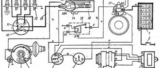
For reconfiguration and operation, you will also need a new UAZ 31514 wiring diagram, which is shown in the photo below, and which you can print for convenience.
You can also make your ignition system more powerful by upgrading it with two kits at once:
- Two switches;
- Two Hall sensors;
- Two ignition coils.
With this approach, each subsystem will be responsible for sparking 2 cylinders at once:
- First and third;
- Second and fourth.
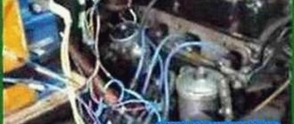
Most often, UAZ cars that take part in competitions or are used by professional fishermen and hunters are subjected to such serious modifications. The video below shows how an engine works with such a system.
Advice: if you use your UAZ 31514 in everyday life, not related to extreme sports, then it is enough to limit yourself to alterations with one set - it’s easier to maintain it. After all, it is used on domestic all-terrain vehicles.
Installation of the UAZ distributor drive
Installing a distributor drive on a UAZ vehicle involves combining a camshaft and an oil pump. It's not very simple.
The distributor drive is driven into rotation by the camshaft gear, at the same time, the oil pump is driven into rotation by the distributor drive through the plate. Removing the drive is not difficult; unscrew the two fastening nuts and remove it from the engine block. The drive may burn in the motor block housing. In this case, you have to use ingenuity. Or try to rock it. Or unscrew the mounting pins and try to turn it. Why does the drive fail? As a rule, this happens when starting the car in cold weather. The oil becomes very thick, and it is very difficult to turn the oil pump. Therefore, the pump will stall, causing the plate to bend. And it gets out of engagement with the oil pump.
Installation of the UAZ distributor drive
After removing the drive, the distributor drive is reinstalled. To do this, set the piston of the first cylinder to TDC at the moment of fuel compression. The easiest way to set this position is to unscrew the spark plug of the first cylinder and block the hole with a paper stopper. When bringing the piston in at the moment of compression, the plug will be knocked out, and then install the generator drive pulley at the first mark.
Correct camshaft position
I would like to note that the piston approaches the TDC position twice during the cylinder operating cycle. For the first time at the moment of compression. The second is at the moment of exhaust gas emission. It is very important not to confuse these provisions. Therefore, we check ourselves by determining the compression occurring in the cylinder. Since at the moment the valves are closed and fuel compression occurs. So, we have installed the piston at TDC. Now our task is to install the drive correctly. Pay attention to the groove into which the distributor drive coupling is inserted; it is offset from the center. This groove must have a direction parallel to the cylinder block. And relative to the center it is offset from the engine block.
The distributor at the junction with the pipe has a similar offset
The drive gear is helical, so if we start inserting the drive in this position. It will not install correctly, but will turn one tooth. Therefore, before inserting the drive, it must be turned one tooth counterclockwise. So that the drive is installed in its place and takes the correct position. Try to engage the edge of the drive gear with the gear on the camshaft. The drive cannot be installed immediately. It is necessary to rotate the crankshaft until the plate fits into the groove of the oil pump. When turning the crankshaft, it is necessary to press the drive. To prevent the edge of the gear from becoming disengaged.
Once the oil pump groove is aligned with the drive plate. The drive will sit in place. After this, it is necessary to again set the piston to the TDC position at the moment of compression, and check the position of the drive groove. If it is parallel to the block and offset from the block, then the distributor drive is installed correctly. If not, this procedure must be repeated.
Drive plate alignment
There is one very big problem during installation. The oil pump drive plate is not firmly fixed along the drive axis. Therefore, when we install the drive, it deviates relative to the axis and does not fall into the groove of the oil pump. It needs to be fixed somehow. I simply inserted matches on both sides, and this fixation was enough for me to install the drive. After the drive is correctly seated in its place, fasten it with nuts.
Source
Design of the GAZ-53 ignition system
In order to repair and configure the SZ on the GAZ-53, you need to know how it works.
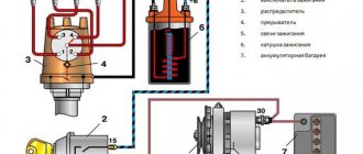
These trucks are equipped with a contactless protection system, which consists of the following components:
Knowing the structure of the protection system, the connection diagram of the protection device and its other components, as well as the functions that each element performs, you can identify problems based on their symptoms and eliminate their cause. All components of the system can be divided into groups according to the tasks performed.
For normal operation of the internal combustion engine, the following conditions must be met:
The entire electronic ignition system consists of two circuits: primary and secondary.
The primary includes the following elements:
The secondary circuit includes:
When the primary circuit receives power, a magnetic field is generated in the breaker. The rotation of the distributor interrupts the current in this place, which leads to the disappearance of the magnetic field. At this moment, a signal appears on the secondary winding, which goes to the cylinders.
Photo gallery
Successful sparking is ensured by stable operation of the motor and the appearance of sufficient voltage on the electrodes. The power of the spark is affected by the size of the gaps between the electrodes and the amount of incoming voltage.
With a weak spark or its absence, fuel consumption increases and engine power decreases.
We install and configure the ignition, change the distributor drive on UAZ vehicles
The UAZ distributor is considered one of the important components of the ignition system in a vehicle. Correct adjustment of this mechanism ensures optimal operation of the power unit as a whole. You can learn more about the principle of operation of the ignition system and how to set it up correctly with your own hands from this material.
Spark plug gap. What should it be and what does it affect?
Although spark plugs are simple, they must be handled and used correctly. They should be properly cleaned, selected and replaced. However, even new versions can sometimes cause problems - the car may run unevenly, sometimes there are jerks during acceleration, as well as slight detonation. Many people immediately begin to look for the cause in the ignition system - of course, the spark plugs are new! However, the gap between the electrodes may be the culprit, just fix it and the engine will just start singing...
ARTICLE TITLE
First a little definition.
The spark plug gap is the distance between the top and bottom electrodes for optimal performance and ignition of the fuel mixture. If this clearance deviates from the recommended specifications, the engine will run rough and you may experience jerking or knocking similar to your engine.
Simply put, if the gap differs from the norm set by the factory or dealer, then you can even half the engine and still not find the reason. It is especially strong in carburetor systems. But first, I suggest you start with the device and operating principle.
Review of SZ on famous UAZs
What is the connection diagram for electronic or contactless ignition on a UAZ 417, how to convert contact ignition to contactless? Why does the coil heat up and how to adjust and adjust the advance angle? First, let’s look at the main points regarding the action and types of SZ.
Operating principle of SZ
Contact system diagram
The ignition system, or rather its correct setting, plays a big role in the operation and starting of a car engine. With correct adjustment, the combustible mixture will burn correctly in the power unit as a result of the supply of charge through the spark plugs. A spark plug is placed on each cylinder of the UAZ engine, each of which is turned on in a certain order, in turn, delivering a discharge to the cylinder after a certain time. It must be taken into account that any SZ makes it possible not only to deliver the required discharge, but also determines its strength.
Due to its technical characteristics, the car’s battery cannot produce the voltage and current required to ignite the mixture. This is due to the fact that the battery can only produce a current of a certain strength. And thanks to the correct operation of the system, the current value increases significantly, which allows you to successfully ignite the air-fuel mixture.
The operating principle of the system consists of several stages:
- First, the driver inserts the key into the ignition and turns it, electrical energy is stored in a coil.
- Then the coil converts the low-voltage voltage in the on-board network of 12 volts into high-voltage. As a result, the voltage value increases to 30 thousand V.
- After this, the discharge is distributed and supplied to one or another spark plug.
- The candle itself produces a spark that ignites the mixture.
Diagram of the UAZ contactless system
What types of SZ are there?
Domestic UAZ vehicles can use one of three ignition systems; let’s look at each of them in detail:
- Contact view. This type of SZ is outdated, however, it is used on most machines. In such a system, the principle of operation is to issue a certain impulse that is formed in a distributor - a distribution device. The contact system is considered one of the simplest in terms of design, which is an advantage, since if a malfunction occurs, the car owner will be able to independently check and repair the system. In addition, prices for structural parts of the contact system are usually affordable, which is good news. The contact SZ includes a coil, a switchgear, a breaker, a capacitor and spark plugs.
- Non-contact type, also called transistor type. Compared to the contact system, the contactless system has more advantages. The resulting spark has a higher power, which is achieved due to the formation of high voltage in the secondary winding of the coil. Also, contactless systems are equipped with an electromagnetic device, which makes it possible to achieve more stable operation of the engine. Ultimately, if the UAZ power unit is configured correctly, then by using a contactless system you can not only increase its power, but also achieve fuel savings, albeit insignificant. Also, such systems are easier to maintain. One of the main nuances in terms of maintenance is the need to periodically lubricate the distributor drive - at least every 10 thousand kilometers. One of the main disadvantages is the difficulty of repair. In practice, repairing a contactless SZ will be problematic, since diagnosing the system will require equipment that is usually available at a service station.
- The ignition system can also be electronic. This option is currently considered one of the most progressive and expensive; it is installed mainly on new cars. Compared with contact and non-contact systems, the electronic system has a more complex structure. The main advantage of this system is that, if necessary, the process of adjusting the ignition angle will be much easier. In addition, there are no contacts in the electronic system that are susceptible to oxidation. It should also be noted that in practice, the combustible mixture in the cylinders of a power unit with an electronic system almost always burns completely. But despite all the advantages, electronic repair systems also have their disadvantages, which relate to device repair. It is almost impossible to repair such an SZ with your own hands, since to perform this task, again, you will need equipment (video published by Nail Poroshin).
Why turn on the ignition?
Connection diagram of components in the ignition system
To properly configure and adjust the operation of the engine cylinders on the UAZ-469, you must have certain skills. We will talk about them later, but first we suggest you find out for what purposes the contactless ignition should be set correctly and what this can entail. After connecting the key to the ignition switch, multiple components and mechanisms come into play, without which the functionality of the engine would be impossible.
So, why set this parameter:
- The motor will operate optimally and stably in all modes. Otherwise, its operation will be unstable and cause inconvenience for the car enthusiast.
- Cold starting of the power unit will be significantly improved. Naturally, if you want to start the engine without problems in thirty-degree frost, then for this you will also need to fill the engine with the appropriate oil and check the performance of the spark plugs.
- Fuel consumption is normalized, otherwise it may be increased.
- The power of the power unit will be optimal, as noted in the service book (the author of the video is the smotri Vidik channel).
Expert recommendations on how to configure correctly
So, how to set the advance angle yourself in order to achieve proper operation of the UAZ engine:
- First of all, you must lock your car in one place by pulling the parking brake lever. Rotate the crankshaft so that the piston of cylinder 1 reaches TDC (top point). In this case, you need to ensure that the hole on the crankshaft pulley coincides with the mark marked on the timing gear cover.
- After this, remove the cover from the distribution mechanism. After dismantling, you will be able to see the slider, which is located inside the cover itself, opposite the contact. If there is no slider, you should turn the crankshaft 180 degrees again, and then set the octane corrector to 0. Using a wrench, you will need to screw the pointer to the distribution mechanism housing so that it aligns with the middle mark. When these steps are completed, the fastening bolt with which the plates are attached to the distributor body must be loosened slightly.
- Then, holding the slider in one place with a finger to prevent it from rotating, you need to carefully rotate the housing itself, this will allow you to remove possible backlash in the drive. The housing must be rotated until you achieve alignment of the sharp end of the stator mechanism petal with the red mark located on the rotor device. After this, the plate itself must be secured to the body using the appropriate bolt.
- Once you have completed these steps, you need to replace the controller cover and check the high voltage cables. You need to make sure that these wires are installed in the correct sequence, taking into account the firing order of the cylinders. When you manage to correctly adjust the lead angle, you need to make sure that the entire procedure was performed correctly.
- To diagnose the correctness of the actions performed, you need to start the engine of your UAZ and wait about 5-10 minutes until the power unit warms up. The operating temperature of the engine is about 90 degrees; you can wait until the internal combustion engine warms up to 80 degrees. Then you need to drive onto a flat road and accelerate the car to 40 km/h, after which you should sharply press the gas. At this moment, the car will accelerate and if, when the speed increases to 60 km/h, a short-term detonation (metallic knock) is heard from under the hood, then this indicates that all actions were performed correctly. If the detonation is too long, the system will need to be adjusted. To do this, the housing of the distribution mechanism will need to be turned one notch or half, and it must be turned counterclockwise. If the diagnostics showed that there is no knocking of the “fingers” at all, then the advance angle should be increased. To do this, the mechanism should be turned in the opposite direction.
Photo gallery “How to adjust correctly”
Ignition system elements
The elements of ignition of fuel in the engine are dominant. Through it, the power unit is started. A couple of types of ignition systems have been developed for gasoline engines:
The elements for igniting a combustible gasoline engine are given in the list:
- distributor or spark breaker. Installed to determine the moment in ignition when a spark appears and transfers high voltage to the engine cylinders. The device combines its work with the movement of pistons in the cylinders;
- coil;
- switch. This part extinguishes the flow of electricity to the coil winding and turns the signal from the regulator into a current signal;
- candles;
- lock;
- starter;
- resistance. Sometimes they add.
Attention! On an engine from a Gazelle or UAZ, a non-contact ignition system is used. A generator is added to it to control signals and devices to regulate advance: vacuum and centrifugal.
Experienced mechanics advise reading the characteristics given below to set the ignition correctly:
- The operation of the engine cylinders is carried out in this way: one, two, four, three;
- the rotor device always rotates counter-minutewise;
- the centrifugal part has a lead angle of eighteen degrees;
- the vacuum part has a lead angle of ten degrees;
- SZ play does not exceed 0.8 mm;
- R resistor does not exceed 8 kOhm;
- R SZ no more than 7 kOhm;
- R in the stator winding – 0.5 kOhm.
Now let's talk about how ignition of fuel in the power unit works.
A guide to replacing a distributor with an oil pump drive
Before installing a new distributor with a drive, you need to weigh your strengths, since it is not recommended to make mistakes when performing work.
So, how to replace and install the distributor:
- Turn off the ignition and remove the distributor cover; the tips and high-voltage cables are connected to it.
- Then you need to disconnect the wire connected to the switch from the distribution mechanism. You also need to disconnect the pipe connected to the vacuum regulator.
- Taking a 13mm wrench, unscrew the two nuts securing the device and remove the mechanism along with the oil pump drive from the power unit.
- After completing these steps, you will be able to see the gasket located under the drive. If as a result of these actions the position of the crankshaft has not changed, then simply install a new mechanism, making sure that the slider is located opposite the mark. All actions are performed in reverse order. When the installation is completed, the advance angle is adjusted.
- If, as a result, the location of the shaft has changed, then before installation it is necessary to move the piston of cylinder 1 to top dead center. You need to ensure that the marks on the pulley align with the pointer on the motor itself.
Procedure for adjusting the ignition system
To correctly adjust the ignition, you need not only to set the advance angles, but also to position the marks correctly. By the way, if the car owner does not understand and does not understand the design of the engine, then it is better to give this work to experienced mechanics in the service center.
Let's look at all the nuances of ignition adjustment.
Label matching
To correctly compare the marks and set the engine ignition, do the following:
- Set the first cylinder to top dead center.
- The crankshaft is turned so that the mark on its pulley aligns with the mark on the cylinder head.
To do these steps, you will need to remove the spark plug from the first cylinder and plug the hole with a rag. Rotate the crankshaft until this rag is removed by air, which creates pressure inside the cylinder.
Similar article How to properly check the engine oil level
Such actions will help to find the end of the compression stroke, otherwise the top dead center of the cylinder.
Advance angle adjustment
To set the ignition timing of the ZMZ 402, you need to do the following:
- Slightly unscrew the octane number corrector bolt on the distributor.
- Set the advance angle on the engine to the center of the scale.
- Slightly unscrew the screw that secures the plates of the octane correction device.
- Rotate the distributor until the red mark on the rotor head is directly in front of the mark on the stator.
The car owner must then hold the engine distributor with one hand. And with his second hand he will tighten the screws. This is how the ZMZ 402 ignition is set.
Checking the correct installation of the ignition
Now the car owner will only have to check that the ignition is installed correctly. Whether he installed the ignition correctly or not can be determined as follows:
- Accelerate the vehicle to 60 kilometers per hour.
- At this speed, press the gas pedal sharply.
- Detonation will occur within three seconds.
- If it does not continue in the future, then the engine ignition was set correctly.
Attention! Experienced mechanics set the ignition in the engine using a strobe light.
List of car models in which it was installed
The UMZ 417 engine was designed specifically for the Ulyanovsk Automobile Plant, therefore it was used in UAZ cars:
- 3151 – jeep;
- 3303 – all-wheel drive truck;
- 3741 – all-metal 4x4 van;
- 2206 – 8 – 11 seat minibus;
- 3962 – ambulance and resuscitation vehicle;
- 3909 – Carriage type peasant;
- 39094 – Peasant truck;
- DISA-1912 Zaslon - an armored vehicle for collectors.
The motor was created a little later than the renaming of UAZ 469 to 3151, and UAZ 452 to 3741, therefore it is used exclusively in the modernized “Bobiki” and “Tabletki” - “Loaves”. The properties of the motor made it possible to use it as a power drive for all UAZ models produced at that time.
Setting the ignition timing on the UMZ-421 engine.
— remove the cover of the sensor-distributor; — Unscrew the spark plug of the first cylinder; — close the hole for the spark plug of the first cylinder with your finger; - turn the engine crankshaft until air begins to escape from under the finger
This will happen first on the compression stroke; - making sure that compression has begun, carefully turning the motor shaft, align the hole on the crankshaft pulley with the pin on the timing gear cover; — making sure that the slider electrode is installed against the terminal on the cover marked “1”, the terminal for the ignition wire of the spark plug of the first cylinder, tighten the bolts so that the octane-corrector indicator of the distributor sensor coincides with the middle division of the octane-corrector; — loosen the bolt securing the octane corrector plates to the sensor-distributor body; - holding your finger on the slider against its rotation, to select the gaps in the drive, slowly turn the housing until the mark on the rotor aligns with the arrowhead on the stator of the sensor-distributor; — tighten the bolt securing the octane corrector plate to the sensor-distributor body and install the cover of the sensor-distributor in place; — install high-voltage wires into the cover of the sensor-distributor in accordance with the operating order of the cylinders 1-2-4-3, counting counterclockwise
After each setting of the ignition timing, check the accuracy of the ignition setting by listening to the engine while the car is moving. For this :
— warm up the engine to a temperature of 60-90 degrees, driving in direct gear on a flat road at a speed of 20-40 km/h; — give the car acceleration, sharply, all the way, by pressing the throttle pedal; — if during all this a slight and short-term detonation is heard, then the ignition timing has been set correctly; — in case of strong detonation, turn the housing of the distribution sensor one division of the octane corrector scale counterclockwise, each division of the scale corresponds to a rotation of the crankshaft by an angle of 4 degrees; — in the complete absence of detonation, turn the sensor-distributor housing one notch clockwise.
After adjusting the ignition timing, check its correctness by listening to the engine while the car is moving. It is necessary to adjust the ignition so that when the engine is under heavy load, only slight detonation is heard. With early ignition, when a powerful detonation is heard, the head gasket may be punctured and the valves and pistons may burn out. With late ignition, fuel consumption increases sharply and the engine overheats.
Wiring diagram for loaf with carburetor engine
To connect electrical appliances to the system of a car with a carburetor, an old standard circuit is used - a loaf of 1954 - 1984, developed for UAZ cars.
Why might a wiring diagram for such a car be useful? The need for notes on wiring in a car may appear not only if a certain defect that interferes with the operation of the vehicle is corrected, but also when the wiring is laid again.
It is worth keeping in mind that there are two circuits for a car with a carburetor engine. The first is the usual one, which does not have an electric carburetor control unit (this element appeared after 1984 and does not fit into old circuits).
The second one is a little more complicated (the connection of the carburetor control unit is taken into account). Such a scheme should be used if you need to connect to the operation of all electrical systems of the car, and not just the ignition and the minimum necessary to drive the vehicle.
If a voltage regulator is not built into the car’s generator, then it must be purchased and connected to the system.
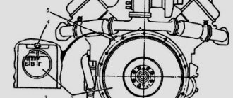
Engine UMZ-421 UAZ: Technical characteristics
In today's market conditions, constant modernization of power plants is necessary, taking this fact into account, the management of the automobile plant in Ulyanovsk began producing the 421 UAZ engine. The unit replaced the “417” motor, which had proven itself in terms of reliability and simplicity.
The follower does not lag behind, having inherited the sought-after traits from the ancestor. Thus, “421”, along with survivability and practicality, shows increased traction and speed characteristics, delighting users. In addition, the unit has increased power and torque impulse. I am glad that the modification has not lost touch with its ancestor in terms of replacement on outdated vehicles. “417” can easily be changed to “421” without additional modifications.
Motor UAZ-421 “Euro-4”:
Engine Description
The UAZ-421 engine has been produced at the plant in Ulyanovsk since 1993. The motor is used for installation on UAZ cars: “469”, “Bukhanka”, “Bars”, “31519”, “Hunter”, etc. The designers decided to replace the outdated “417” unit with a motor, introducing new trends into it.
Thus, an original design of an aluminum frame was used, in which dry liners with thin, cast-iron walls are filled. This made it possible to increase the cross-section of the chambers to 100mm, and leave the same size between the cylinders, 116mm. The solution had a positive effect on the service life of the unit, since rigidity increased and the tendency of the cylinders to become “oval” during operation decreased.
Setting the Ignition Timing on Your Harley
Check ignition timing:
At every 5,000 mile (8,000 km) service interval. Check the correct RPM and Ignition Timing is as follows:
1. See Figure 0. Thread the TIMING MARK VIEW PLUG (Part No. HD 96295-65D) into the timing check hole. Be sure to look at the plugin, it does not touch the flywheel.
1a. See Figure 1. Find the correct evaluation time for your engine. If a shop manual is not available, remove the spark plugs, crank the engine until the front piston is at TDC on compression, press and identify the TDC mark on the flywheel.
2. Connect the INDUCTIVE TIMER leads to the front spark plug cable, battery positive terminal, and ground.
3. Make sure the vacuum hose is properly installed on the carburetor and on the vacuum electric switch (V.O.E.S.).
4.Start the engine. Set the engine speed by turning the idle speed screw clockwise to increase speed or counterclockwise to decrease speed.
Coil device
The UAZ 469 ignition coil has a complex design:
- screw-in terminal with the highest voltage;
- voltage output;
- lid;
- contact spring;
- low voltage clamp;
- gasket for sealing;
- fastening bracket;
- magnetic circuits;
- contact plate;
- primary and secondary winding;
- insulation gaskets;
- frame;
- insulator;
- iron core;
- insulating mass;
- additional resistor and its insulator;
- screw and plate for fastening the resistor.
The distributor performs the function of dispersing and interrupting the ignition of the UAZ 469. It has vacuum and centrifugal regulators. The centrifugal changes the UAZ ignition angle depending on the frequency with which the crankshaft or camshaft rotates.
BSZ spark plugs are a very important element. With their help, the working mixture in the combustion chamber ignites in the cylinders and gives a good spark so that the car starts up quickly. In most cases, they use A12BS spark plugs, which are impossible to disassemble, therefore, in the event of a malfunction, it is necessary to have new ones in stock, which can be quickly and easily replaced.
Many of us remember the famous car.
Therefore, its appearance at the show dedicated to the Olympic Games was perceived as part of our glorious history of the development of the Russian automobile industry.
The loaf was awarded participation in the 2014 Olympics
Precise ignition setting using a strobe light.
IGNITION ON 402 ENGINE. WE INSTALL THE TRANSMBLER DRIVE.
A more precise setting of the ignition timing is made using a strobe light. To do this you should:
— connect the strobe sensor to the high voltage wire of the spark plug of the first cylinder; — start and warm up the engine; — check the engine and, if necessary, adjust the crankshaft speed at idle within 700-750 rpm; — turn on the strobe and point it at the indicator rib on the camshaft gear cover, while the indicator rib and three fixed marks on the crankshaft damper pulley should be visible.
When the ignition is installed correctly, opposite the indicator edge there should be an area between the first and second marks of the damper pulley. If the position of the indicator rib and marks does not correspond to the specified ones, then it is necessary to loosen the bolt securing the sensor-distributor to the drive housing and, with the engine running and the strobe light on, rotate the housing of the sensor-distributor to the optimal position of the indicator rib and marks.