Design and principle of operation of GAZ-3307 drive axles
Content
Introduction
Design and principle of operation of GAZ-3307 drive axles
Diagnostics of GAZ-3307 drive axles
Maintenance of GAZ-3307 drive axles
Main malfunctions of GAZ-3307 drive axles
Repair of GAZ-3307 drive axles
Safety requirements. For vehicle maintenance and repair
Bibliography
Introduction
GAZ-3307 and GAZ-3309 are Russian trucks in the family of the fourth generation of medium-duty trucks produced by the Gorky Automobile Plant. The GAZ-3307 flatbed carburetor truck has been in mass production since the end of 1989, and the GAZ-3309 turbodiesel truck has been in production since mid-1994. The GAZ-3307 replaced the third-generation GAZ-52/53 family, which it completely replaced from the production line by the beginning of 1993. Trucks GAZ-3307 and GAZ-3309 with a load capacity of 4.5 tons are designed for operation on all types of paved roads and are characterized by high technical and operational indicators. The fourth family of GAZ trucks also included the 5-ton diesel truck GAZ-4301 (1984-1994) and the 3-ton diesel truck GAZ-3306 (1993-1995). Since 1999, the 2- and 2.3-ton off-road truck GAZ-3308 "Sadko" (4x4) has been produced, and since 2005 the 4-ton off-road truck GAZ-33086 "Countryman" has been produced.
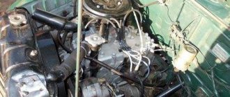
Technical characteristics of the carburetor engine of the GAZ-3307 truck (2008 model)
- Engine
- model ZMZ-5231.10
- description:
V-shaped, 8-cylinder, 4-stroke gasoline engine with liquid cooling, with a carburetor power supply system and an exhaust gas recirculation system (EGR), OHV valve mechanism, aluminum block and cylinder head, third environmental class (Euro-3).
- working volume, l 4.67
- compression ratio 7.6
- gross power hp (kW) / rpm 124 (91.2) / 3200—3400
Max. gross torque, kgf m (N m) / rpm 30.5 (298) / 3000—3400
- minimum specific fuel consumption g/hp h (g/kW) 240 (313)
- weight, kg 275
- fuel: motor gasoline A-76 “Normal” / AI-80 “Standard”
The drive axle of a car is a unit designed to increase torque in the cardan, distribute this moment, and also transmit it to the drive wheel axle, which increases the traction forces of the wheels. The increase in torque and its supply at an angle of 90° is ensured by the main gear; torque is distributed between the drive axles of the wheels using a differential, and is transmitted to the drive wheels by axle shafts.
Design and principle of operation of GAZ-3307 drive axles
Design and principle of operation of GAZ-3307 drive axles
The box-section rear axle housing of GAZ-3307, GAZ-3309 cars is welded from stamped steel casings, to which are welded the rear cover, spring cushions, axles with flanges for installing brake mechanisms and wheel hubs, and a reinforcement for mounting the gearbox.
Design of gearbox and rear axle hubs of GAZ-3307 vehicles.
Rear axle gearbox GAZ-3307,
1 — front cover; 2 — coupling with outer rings of bearings; 3, 19, 23, 31, 34 — bolts; 4, 20 — gaskets; 5, 9, 29, 33 — nuts; 6 - drive gear; 7- flange adapter; 8 — flange with reflector; 10 - cuff; 11 — oil sump ring; 12, 15, 17, 21 — bearings; 13 — adjusting shims; 14 — adjusting ring; 16, 38 - plugs; 18 — retaining ring; 22 — axle gear; 24, 36 — support washers; 25, 28 — differential boxes (right and left); 26 — crosspiece; 27 — driven gear; 30 — differential bearing cover; 32 — locking plate; 35 — satellite; 37 — adjusting screw; 39 - bushing; 40 — oil receiving tube; 41 — gear housing
Content
Introduction
Design and principle of operation of GAZ-3307 drive axles
Diagnostics of GAZ-3307 drive axles
Maintenance of GAZ-3307 drive axles
Main malfunctions of GAZ-3307 drive axles
Repair of GAZ-3307 drive axles
Safety requirements. For vehicle maintenance and repair
Bibliography
Introduction
GAZ-3307 and GAZ-3309 are Russian trucks in the family of the fourth generation of medium-duty trucks produced by the Gorky Automobile Plant. The GAZ-3307 flatbed carburetor truck has been in mass production since the end of 1989, and the GAZ-3309 turbodiesel truck has been in production since mid-1994. The GAZ-3307 replaced the third-generation GAZ-52/53 family, which it completely replaced from the production line by the beginning of 1993. Trucks GAZ-3307 and GAZ-3309 with a load capacity of 4.5 tons are designed for operation on all types of paved roads and are characterized by high technical and operational indicators. The fourth family of GAZ trucks also included the 5-ton diesel truck GAZ-4301 (1984-1994) and the 3-ton diesel truck GAZ-3306 (1993-1995). Since 1999, the 2- and 2.3-ton off-road truck GAZ-3308 "Sadko" (4x4) has been produced, and since 2005 the 4-ton off-road truck GAZ-33086 "Countryman" has been produced.
Technical characteristics of the carburetor engine of the GAZ-3307 truck (2008 model)
- Engine
- model ZMZ-5231.10
- description:
V-shaped, 8-cylinder, 4-stroke gasoline engine with liquid cooling, with a carburetor power supply system and an exhaust gas recirculation system (EGR), OHV valve mechanism, aluminum block and cylinder head, third environmental class (Euro-3).
- working volume, l 4.67
- compression ratio 7.6
- gross power hp (kW) / rpm 124 (91.2) / 3200—3400
Max. gross torque, kgf m (N m) / rpm 30.5 (298) / 3000—3400
- minimum specific fuel consumption g/hp h (g/kW) 240 (313)
- weight, kg 275
- fuel: motor gasoline A-76 “Normal” / AI-80 “Standard”
The drive axle of a car is a unit designed to increase torque in the cardan, distribute this moment, and also transmit it to the drive wheel axle, which increases the traction forces of the wheels. The increase in torque and its supply at an angle of 90° is ensured by the main gear; torque is distributed between the drive axles of the wheels using a differential, and is transmitted to the drive wheels by axle shafts.
Design and principle of operation of GAZ-3307 drive axles
Design and principle of operation of GAZ-3307 drive axles
The box-section rear axle housing of GAZ-3307, GAZ-3309 cars is welded from stamped steel casings, to which are welded the rear cover, spring cushions, axles with flanges for installing brake mechanisms and wheel hubs, and a reinforcement for mounting the gearbox.
Design of gearbox and rear axle hubs of GAZ-3307 vehicles.
Rear axle gearbox GAZ-3307,
1 — front cover; 2 — coupling with outer rings of bearings; 3, 19, 23, 31, 34 — bolts; 4, 20 — gaskets; 5, 9, 29, 33 — nuts; 6 - drive gear; 7- flange adapter; 8 — flange with reflector; 10 - cuff; 11 — oil sump ring; 12, 15, 17, 21 — bearings; 13 — adjusting shims; 14 — adjusting ring; 16, 38 - plugs; 18 — retaining ring; 22 — axle gear; 24, 36 — support washers; 25, 28 — differential boxes (right and left); 26 — crosspiece; 27 — driven gear; 30 — differential bearing cover; 32 — locking plate; 35 — satellite; 37 — adjusting screw; 39 - bushing; 40 — oil receiving tube; 41 — gear housing
______________________________________________________________________________
Rear axle of GAZ-3307, GAZ-3309 cars
The box-section rear axle housing of GAZ-3307, GAZ-3309 cars is welded from stamped steel casings, to which are welded the rear cover, spring cushions, axles with flanges for installing brake mechanisms and wheel hubs, and a reinforcement for mounting the gearbox. The design of the gearbox and rear axle hubs of the GAZ-3307, GAZ-3309 vehicles is shown in Fig. 1 and 2.
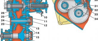
Rice. 1. Rear axle gearbox GAZ-3307, GAZ-3309
1 — front cover; 2 — coupling with outer rings of bearings; 3, 19, 23, 31, 34 — bolts; 4, 20 — gaskets; 5, 9, 29, 33 — nuts; 6 - drive gear; 7- flange adapter; 8 — flange with reflector; 10 - cuff; 11 — oil sump ring; 12, 15, 17, 21 — bearings; 13 — adjusting shims; 14 — adjusting ring; 16, 38 - plugs; 18 — retaining ring; 22 — axle gear; 24, 36 — support washers; 25, 28 — differential boxes (right and left); 26 — crosspiece; 27 — driven gear; 30 — differential bearing cover; 32 — locking plate; 35 — satellite; 37 — adjusting screw; 39 - bushing; 40 — oil receiving tube; 41 - gearbox housing The rear axle gearbox of GAZ-3307, GAZ-3309 is assembled in a separate cast housing 41 (see Fig. 1) made of high-strength cast iron, which is installed in the hole of the axle housing and secured with bolts 34.
The gearbox housing contains a 2 bearing clutch with drive gear b, flange 8 and flange adapter 7, as well as a differential, the housing of which consists of right 25 and left 28 boxes connected by bolts 23. Driven gear 27 is secured to the left box with bolts and nuts. The main gear of the rear axle gearbox GAZ-3307, GAZ-3309 is hypoid. The axis of the drive gear is shifted downwards relative to the axis of the driven gear by 32 mm.
The preload of the drive gear bearings is adjusted by ring 14, located between the inner races of tapered bearings 12 and 15. To prevent excessive deformation of the driven gear, a stop is installed in the crankcase, adjustable by screw 37. The GAZ-3307, GAZ-3309 differential assembly with tapered bearings 21 is installed in sockets of the gearbox housing, closed with covers 30, secured with bolts. The preload of the differential bearings is adjusted with nuts 33. The same nuts are used to adjust the lateral clearance in the meshing of the main gear gears. In the differential housing of the gearbox of the GAZ-3307, GAZ-3309 bridge, gears 22 of the axle shafts and four satellites 35 are installed, placed on the spikes of the crosspiece 26. Support washers 24 and 36 are installed under the satellites and semi-axial gears. Axle shafts 2 are inserted into the splined holes of the semi-axial gears (Fig. 2), attached by a flange to the wheel hub with nuts and studs. The rear wheel hubs rotate on tapered roller bearings 4 and 5, mounted on the axles of the rear axle GAZ-3307, GAZ-3309. The bearing is fastened and adjusted using a nut 15 screwed onto the threaded end of the crankcase journal. The adjusting nut is locked with washer 16 and nut 11. On the inside of the hub there is a cuff 11 installed, which prevents lubricant from leaving the hub, and an oil deflector 8 with an O-ring and a tube to protect the brake linings from oil.
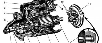
Rice. 2. Rear axle hub GAZ-3307, GAZ-3309 1 - bolt; 2 - axle shaft; 3 - gasket; 4, 5 — bearings; 6 - brake drum; 7 — ABS rotor; 8 — oil deflector with sealing ring and tube; 9, 18 — nuts; 10 - bushing; 11 - cuff; 12 — rear brake; 13 - thrust ring; 14 — hub: 15, 17 — bearing nuts; 16 - lock washer Removing the rear axle of GAZ-3307, GAZ-3309 vehicles Removing the axle from the vehicle must be carried out in the following order: - loosen the rear wheel nuts - disconnect the propeller shaft from the drive gear flange adapter (from the drive gear flange); — disconnect the parking brake drive cables from the equalizer; — Disconnect the brake system hoses, remove the brake pipes. Disconnect electrical cables and ABS sensors; — unscrew the nuts securing the spring ladders, remove the ladders, pads and spring linings; Before disassembling, you must unscrew the drain plug and drain the oil. Disassembly of the rear axle GAZ-3307, GAZ-3309 must be carried out in the following order: - unscrew the nuts securing the axle shafts and remove the axle shafts using a dismantling bolt - remove the axle shaft flange gaskets; - Unscrew the lock nut of the outer hub bearing, remove the lock washer, unscrew the inner nut of the hub bearing; — remove the brake drum and hub assembly; — press out the cuff, thrust washer and inner ring of the bearing. The cuff must be replaced when the working edge hardens or there are cracks due to rubber aging; — in case of bearing replacement, press out the outer ring of the inner bearing from the rear axle hub of GAZ-3307, GAZ-3309 using a puller and gripper. Place the gripper legs under the end of the ring and spread them all the way by screwing the bolt into the axle. Remove the bearing ring by rotating the puller screw; — press out the outer ring of the outer hub bearing in the same way; — Unscrew the fastening bolts and remove the oil deflector assembly; — unscrew the nuts, remove the bolts securing the ends to the crankcase flange and remove the brake assembly and oil deflector brackets; — Unscrew the nuts of the mounting bolts and remove the drive gear flange adapter; — Unscrew the bolts securing the gearbox to the crankcase and remove the gearbox using the dismantling bolts; — remove the gearbox gasket; — unscrew the breather; — to remove a worn cuff bushing from the crankcase axle, remove a layer of metal from the surface of the bushing with a depth of at least 3 mm in two diametrically opposite places and cut the bushing with a chisel without damaging the surface of the axle crankcase axle axle. Disassembling the rear axle gearbox GAZ-3307, GAZ-3309 Disassembling the gearbox must be carried out in the following order: - unscrew the inspection hole plug; — unscrew the plug of the oil intake pipe; — Unscrew the fastening bolt and remove the spring, plate and tube from the oil channel; — unlock and unscrew the adjusting screw of the stop; — remove the bushing and spring ring from the adjusting screw; — Unscrew the bolts securing the locking plates of the differential bearing nuts, remove the locking plates; — unscrew the adjusting nuts 33 (see Fig. 1) using a special wrench. Disassembling the rear axle gearbox of GAZ-3307, GAZ-3309 must be carried out in the following order: - unscrew the nut on the shank of the drive gear; — unscrew the nut and remove the washer; — remove the flange of the drive gear of the rear axle gearbox GAZ-3307, GAZ-3309; — remove the front cover, gasket and oil sump ring; — remove the bearing coupling together with the inner ring of the front tapered bearing; — remove the adjusting ring; — in case of replacement, compress the inner ring of the rear tapered bearing using a puller, installing the liners into it. To remove the bearing ring, compress the support nuts with the support nuts until the shoulders of the liners contact the end of the inner ring of the bearing or the thrust shoulder of the inner ring rollers; to do this, it is necessary to remove the rollers. Dismantling the differential of the GAZ-3307, GAZ-3309 axle must be carried out in the following order: - unscrew the nuts and remove the bolts securing the driven gear to the differential boxes; — remove the driven gear from the differential box; — bend the locking plate, unscrew the bolt and remove the oil catcher; — in case of replacement, press the inner rings of the bearings from the right and left differential boxes. To do this, you need to use a puller with liners; — unscrew the bolts securing the GAZ-3307, GAZ-3309 differential boxes, disconnect the boxes, remove the crosspiece, axle gears, support washers, remove the support washers and satellites from the crosspiece. Adjustment of the main gear of the rear axle GAZ-3307, GAZ-3309 Bearings and gearing of the main gear of the GAZ-3307, GAZ-3309 are adjusted at the factory and, as a rule, do not require adjustment in operation. Their adjustment is necessary only after reassembling the bridge and when replacing any parts or when there is significant wear on the bearings. The lateral clearance in the meshing of the main gears, which has increased due to tooth wear, cannot be reduced by adjustment, as this will lead to a disruption of the meshing of the teeth. This will result in increased noise or tooth breakage. Play in tapered bearings should be eliminated without disturbing the relative position of the driven and drive gears. Below is the procedure for making various adjustments. Adjusting the preload of the drive gear bearings of the GAZ-3307, GAZ-3309 gearbox The need for bearing adjustment can be determined by the presence of axial play in the drive gear shaft. Axial play is measured using an indicator device (the flange adapter is removed) when moving the drive gear shaft from one extreme position to another, and in the absence of a device, by rocking the flange by hand. If there is axial play of the drive gear in tapered bearings of more than 0.03 mm, you must first tighten the flange nut. To do this, unscrew the nut and tighten it to a torque of 280-400 Nm (28-40 kg/cm). If, after tightening the nut, the moment of resistance to rotation of the drive gear of the main gear of the rear axle GAZ-3307, GAZ-3309 is greater than the norm specified below, it means that the ends of the inner rings of the bearings and the adjusting ring are heavily worn. In this case, to adjust the bearings, it is necessary to select a thicker ring. Adjusting rings, produced in thicknesses of 12.10-12.94 mm, are divided into 22 groups. The thickness of the rings of adjacent groups differs by 0.04 mm. If the thickness of the adjusting ring exceeds the required one, then tightening the nut will not eliminate the backlash and increase the resistance when the drive gear rotates in the bearings. In this case, it is necessary to adjust the preload of the main drive bearings of the GAZ-3307, GAZ-3309 axle by reducing the thickness of the adjusting ring installed between the inner rings of the tapered bearings. To do this, you must do the following: - remove the drive gear assembly; — unscrew the flange mounting nut; — remove the flange, oil seal cover, oil sump ring, inner ring of the outer bearing and adjusting ring. Select an adjusting ring with a thinner thickness. The reduction in ring thickness should be equal to the sum of the axial play measured by the indicator and the value of 0.05 mm (bearing preload). Reassemble the coupling in reverse order and tighten the nut. When tightening the nut, it is necessary to rotate the drive gear of the main gear of GAZ-3307, GAZ-3309 for proper installation of the rollers in the bearings. Tighten the nut with the torque specified above, and one of its slots should coincide with the hole for the cotter pin. You cannot even turn the nut back a little so that the hole for the cotter pin matches the slot of the nut, since insufficient tightening may cause the inner ring of the outer bearing to rotate, wear out the adjusting ring, and, as a result, increase the backlash of the drive gear. Check the tightness of the bearings. With proper adjustment, the moment of resistance to rotation of the drive gear should be in the range of 1.5-3.0 Nm (0.15-0.30 kg/cm). The test should be carried out using a dynamometer. To do this, clamp the coupling in a vice, hook the dynamometer hook onto the flange hole and smoothly turn the gear. The readings on the dynamometer scale should be in the range of 29-51 N (2.9-5.1 kgf). If the moment of resistance to rotation of the bearings is within normal limits, you need to tighten the nut and install the drive gear assembly in the rear axle housing of GAZ-3307, GAZ-3309, otherwise it is necessary to repeat the adjustment. If it turns out that the torque resistance to rotation is less than the required one, it is necessary to reduce the thickness of the adjusting ring, and if it exceeds the required one, then it is necessary to select a ring of greater thickness.
______________________________________________________________________________
______________________________________________________________________________
- Clutch GAZ-3308, 3309
- Dismantling the GAZ-3308, 3309 gearbox
- Drive axles GAZ-3308
- Transfer case and cardans GAZ-3308
- Cardans GAZ-3307, 3309
- Rear axle GAZ-3309, 3307
- Suspension GAZ-3309
- Steering GAZ-3309
______________________________________________________________________________
______________________________________________________________________________
- Clutch GAZ-53, 3307
- Gearbox GAZ-53, 66
- Rear axle GAZ-53
- Steering GAZ-53, 66
- Ignition installation GAZ-53
- Clutch GAZ-66
- Drive axles GAZ-66
- Brake system GAZ-66
- Winch and power take-off GAZ-66
- Operating systems of the GAZ-66, GAZ-3307 engine
- Engine ZMZ-402 Gazelle GAZ-2705
- Clutch Gazelle GAZ-2705
- Gazelle GAZ-2705 gearbox
- Front axle Gazelle GAZ-2705
- Cylinder head and camshaft Cummins ISF 2.8
- Fuel system of the Gazelle Cummins ISF 2.8 engine
- Cylinder block and piston group of the Cummins ISF 2.8 engine
- Crankshaft engine Cummins ISF 2.8 Gazelle
- Engine Cummins Valdai GAZ-33106
- Clutch and gearbox Valdai
- Bridges Valdai
- Steering Valdai
Catalogs of spare parts and assembly parts
ZIL 130, ZIL 131, GAZ 3307, GAZ 3102, GAZ 3110, GAZ 53, MAZ 500, T 25, T40, Izh Planet, Izh Jupiter
Before removing the covers, pay attention to the marks (in the form of identical numbers) that must be placed on the outer surfaces of the covers and the side surfaces of the gearbox housing in order to avoid unacceptable disassembly of these parts (since at the factory, boring holes and threading were carried out in the housing with already installed covers ).
Remove the outer rings of the differential bearings and their adjusting nuts.
Remove the differential assembly from the crankcase.
Remove the bolts securing the drive gear bearing clutch. Press the drive gear assembly out of the gearbox housing.
Remove the adjusting shims from the crankcase neck.
Disassembling the drive gear. Unscrew the nut on the drive gear shank.
Unscrew the nut and remove the washer. Remove the driveshaft flange. Remove the front cover, gasket and oil distillation ring.
Remove the bearing clutch along with the inner ring of the front tapered bearing, the adjusting ring and the clutch shims.
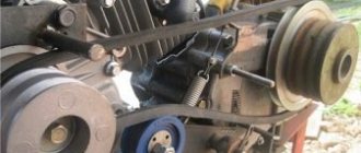
Remove the inner race of the rear tapered roller bearing. To do this, use a puller with an insert installed in it (Fig. 2). At the same time, use nuts 3 to compress the supports 2 until the liners contact the bearing race and the rotation of the screw compresses the bearing ring.
Press the drive gear oil seal out of the front cover.
Remove the retaining ring of the cylindrical roller bearing and press the bearing. If the outer rings of the bevel bearings of the drive gear are unsuitable, they are removed. When repairing bearing couplings, it is taken into account that at the factory, after boring the bearing seats and pressing the outer bearing rings into them, further processing of the coupling is carried out on the basis of these rings. When repairing a bridge, whenever possible, use a coupling without pressing out the outer rings of the bearings.
Disassembling the differential. Unscrew the lock nuts, then unscrew the nuts and remove the bolts securing the driven gear to the differential box.
Remove the driven gear from the differential box.
Bend the locking plate, unscrew the bolt and remove the oil catcher. Remove the inner races of the differential bearings from the left and right differential boxes.
Unscrew the differential mounting bolts, disconnect the differential boxes, remove the support washers, satellites, axle gears and crosspiece.
Similar articles:
- Rear axle disassembly
- Rear axle device
- Rear axle assembly
- Inspection and control of rear axle parts
- Gearbox disassembly
TRUCKS GAZ, ZIL, KAMAZ, URAL, MAZ, KRAZ
_________________________________________________________________________________________
Maintenance of the rear axle GAZ-3307, 3309
The box-section rear axle housing of GAZ-3307, GAZ-3309 cars is welded from stamped steel casings, to which are welded the rear cover, spring cushions, axles with flanges for installing brake mechanisms and wheel hubs, and a reinforcement for mounting the gearbox. The design of the gearbox and rear axle hubs is shown in Fig. 1 and 2. Fig. 1. Rear axle gearbox GAZ-3307, GAZ-3309
1 — front cover; 2 — coupling with outer rings of bearings; 3, 19, 23, 31, 34 — bolts; 4, 20 — gaskets; 5, 9, 29, 33 — nuts; 6 - drive gear; 7- flange adapter; 8 — flange with reflector; 10 - cuff; 11 — oil sump ring; 12, 15, 17, 21 — bearings; 13 — adjusting shims; 14 — adjusting ring; 16, 38 - plugs; 18 — retaining ring; 22 — axle gear; 24, 36 — support washers; 25, 28 — differential boxes (right and left); 26 — crosspiece; 27 — driven gear; 30 — differential bearing cover; 32 — locking plate; 35 — satellite; 37 — adjusting screw; 39 - bushing; 40 — oil receiving tube; 41 - gearbox housing The rear axle gearbox of GAZ-3307, GAZ-3309 is assembled in a separate cast housing 41 (see Fig. 1) made of high-strength cast iron, which is installed in the hole of the axle housing and secured with bolts 34.
The gearbox housing contains a 2 bearing clutch with drive gear b, flange 8 and flange adapter 7, as well as a differential, the housing of which consists of right 25 and left 28 boxes connected by bolts 23. Driven gear 27 is secured to the left box with bolts and nuts. The main gear of the rear axle gearbox is hypoid. The axis of the drive gear is shifted downwards relative to the axis of the driven gear by 32 mm.
The preload of the drive gear bearings is adjusted by ring 14, located between the inner races of bevel bearings 12 and 15. To prevent excessive deformation of the driven gear, a stop is installed in the crankcase, adjustable by screw 37. The differential assembly with bevel bearings 21 is installed in the gearbox housing sockets, closed by covers 30 , secured with bolts.
The preload of the differential bearings is adjusted with nuts 33. The same nuts are used to adjust the lateral clearance in the meshing of the main gear gears. In the differential housing of the GAZ-3307, GAZ-3309 axle gearbox, gears 22 of the axle shafts and four satellites 35 are installed, located on the spikes of the crosspiece 26.
Support washers 24 and 36 are installed under the satellites and side gears. Axle shafts 2 are inserted into the spline holes of the side gears (Fig. 2), flanged to the wheel hub with nuts and studs. The rear wheel hubs rotate on tapered roller bearings 4 and 5, mounted on the axles of the rear axle GAZ-3307, GAZ-3309. The bearing is fastened and adjusted using a nut 15 screwed onto the threaded end of the crankcase journal. The adjusting nut is locked with washer 16 and nut 11. On the inside of the hub there is a cuff 11 installed, which prevents lubricant from leaving the hub, and an oil deflector 8 with an O-ring and a tube to protect the brake linings from oil. Rice. 2. Rear axle hub GAZ-3307, GAZ-3309 1 - bolt; 2 - axle shaft; 3 - gasket; 4, 5 — bearings; 6 - brake drum; 7 — ABS rotor; 8 — oil deflector with sealing ring and tube; 9, 18 — nuts; 10 - bushing; 11 - cuff; 12 — rear brake; 13 - thrust ring; 14 — hub: 15, 17 — bearing nuts; 16 - lock washer Removing the rear axle of GAZ-3307, GAZ-3309 vehicles Removing the axle from the vehicle must be carried out in the following order: - loosen the rear wheel nuts
— disconnect the propeller shaft from the drive gear flange adapter (from the drive gear flange); — disconnect the parking brake drive cables from the equalizer;
— Disconnect the brake system hoses, remove the brake pipes. Disconnect electrical cables and ABS sensors; — unscrew the nuts securing the spring ladders, remove the ladders, pads and spring linings; Before disassembling, you must unscrew the drain plug and drain the oil. Disassembly of the rear axle GAZ-3307, GAZ-3309 must be carried out in the following order: - unscrew the nuts securing the axle shafts and remove the axle shafts using the dismantling bolt
— remove the axle flange gaskets; - Unscrew the lock nut of the outer hub bearing, remove the lock washer, unscrew the inner nut of the hub bearing;
— remove the brake drum and hub assembly; — press out the cuff, thrust washer and inner ring of the bearing. The cuff must be replaced when the working edge hardens or there are cracks due to rubber aging; — in case of bearing replacement, press the outer ring of the inner bearing out of the rear axle hub using a puller and grabber. Place the gripper legs under the end of the ring and spread them all the way by screwing the bolt into the axle. Remove the bearing ring by rotating the puller screw; — press out the outer ring of the outer hub bearing in the same way;
— Unscrew the fastening bolts and remove the oil deflector assembly; — unscrew the nuts, remove the bolts securing the ends to the crankcase flange and remove the brake assembly and oil deflector brackets;
— Unscrew the nuts of the mounting bolts and remove the drive gear flange adapter; — Unscrew the bolts securing the gearbox to the crankcase and remove the gearbox using the dismantling bolts;
— remove the gearbox gasket;
— unscrew the breather; — to remove a worn cuff bushing from the crankcase axle, remove a layer of metal from the surface of the bushing with a depth of at least 3 mm in two diametrically opposite places and cut the bushing with a chisel without damaging the surface of the axle crankcase axle axle. Disassembling the rear axle gearbox GAZ-3307, GAZ-3309 Disassembling the gearbox must be carried out in the following order: - unscrew the inspection hole plug;
— unscrew the plug of the oil intake pipe; — Unscrew the fastening bolt and remove the spring, plate and tube from the oil channel;
— unlock and unscrew the adjusting screw of the stop; — remove the bushing and spring ring from the adjusting screw;
— Unscrew the bolts securing the locking plates of the differential bearing nuts, remove the locking plates;
— unscrew the adjusting nuts 33 (see Fig. 1) using a special wrench. Disassembling the rear axle gearbox of GAZ-3307, GAZ-3309 must be carried out in the following order: - unscrew the nut on the shank of the drive gear;
— unscrew the nut and remove the washer; — remove the flange of the drive gear of the rear axle reducer;
— remove the front cover, gasket and oil sump ring; — remove the bearing coupling together with the inner ring of the front tapered bearing;
— remove the adjusting ring;
— in case of replacement, compress the inner ring of the rear tapered bearing using a puller, installing the liners into it. To remove the bearing ring, compress the support nuts with the support nuts until the shoulders of the liners contact the end of the inner ring of the bearing or the thrust shoulder of the inner ring rollers; to do this, it is necessary to remove the rollers. Dismantling the differential of the GAZ-3307, GAZ-3309 axle must be carried out in the following order: - unscrew the nuts and remove the bolts securing the driven gear to the differential boxes;
— remove the driven gear from the differential box; — bend the locking plate, unscrew the bolt and remove the oil catcher;
— in case of replacement, press the inner rings of the bearings from the right and left differential boxes. To do this, you need to use a puller with liners; - Unscrew the bolts securing the differential boxes, disconnect the boxes, remove the crosspiece, axle gears, support washers, remove the support washers and satellites from the crosspiece. Adjusting the main gear of the rear axle GAZ-3307, GAZ-3309 The bearings and gearing of the main gear of the GAZ-3307, GAZ-3309 are adjusted at the factory and, as a rule, do not require adjustment in operation.
Their adjustment is necessary only after reassembling the bridge and when replacing any parts or when there is significant wear on the bearings. The lateral clearance in the meshing of the main gears, which has increased due to tooth wear, cannot be reduced by adjustment, as this will lead to a disruption of the meshing of the teeth. This will result in increased noise or tooth breakage. Play in tapered bearings should be eliminated without disturbing the relative position of the driven and drive gears. Below is the procedure for making various adjustments. Adjusting the preload of the drive gear bearings of the GAZ-3307, GAZ-3309 gearbox The need for bearing adjustment can be determined by the presence of axial play in the drive gear shaft.
Axial play is measured using an indicator device (the flange adapter is removed) when moving the drive gear shaft from one extreme position to another, and in the absence of a device, by rocking the flange by hand. If there is axial play of the drive gear in tapered bearings of more than 0.03 mm, you must first tighten the flange nut. To do this, unscrew the nut and tighten it to a torque of 280-400 Nm (28-40 kg/cm). If, after tightening the nut, the moment of resistance to rotation of the drive gear of the main drive of the rear axle is greater than the norm specified below, it means that the ends of the inner rings of the bearings and the adjusting ring are heavily worn. In this case, to adjust the bearings, it is necessary to select a thicker ring. Adjusting rings, produced in thicknesses of 12.10-12.94 mm, are divided into 22 groups. The thickness of the rings of adjacent groups differs by 0.04 mm. If the thickness of the adjusting ring exceeds the required one, then tightening the nut will not eliminate the backlash and increase the resistance when the drive gear rotates in the bearings. In this case, it is necessary to adjust the preload of the main drive bearings of the GAZ-3307, GAZ-3309 axle by reducing the thickness of the adjusting ring installed between the inner rings of the tapered bearings. To do this, you must do the following: - remove the drive gear assembly;
— unscrew the flange mounting nut; — remove the flange, oil seal cover, oil sump ring, inner ring of the outer bearing and adjusting ring. Select an adjusting ring with a thinner thickness. The reduction in ring thickness should be equal to the sum of the axial play measured by the indicator and the value of 0.05 mm (bearing preload). Reassemble the coupling in reverse order and tighten the nut. When tightening the nut, the drive gear of the main gear must be rotated to ensure proper installation of the rollers in the bearings.
Tighten the nut with the torque specified above, and one of its slots should coincide with the hole for the cotter pin. You cannot even turn the nut back a little so that the hole for the cotter pin matches the slot of the nut, since insufficient tightening may cause the inner ring of the outer bearing to rotate, wear out the adjusting ring, and, as a result, increase the backlash of the drive gear. Check the tightness of the bearings. With proper adjustment, the moment of resistance to rotation of the drive gear should be in the range of 1.5-3.0 Nm (0.15-0.30 kg/cm). The test should be carried out using a dynamometer. To do this, clamp the coupling in a vice, hook the dynamometer hook onto the flange hole and smoothly turn the gear. The readings on the dynamometer scale should be in the range of 29-51 N (2.9-5.1 kgf). If the moment of resistance to rotation of the bearings is within the normal range, you need to tighten the nut and install the drive gear assembly into the rear axle housing, otherwise you need to repeat the adjustment. If it turns out that the torque resistance to rotation is less than the required one, it is necessary to reduce the thickness of the adjusting ring, and if it exceeds the required one, then it is necessary to select a ring of greater thickness.
_________________________________________________________________________________________
- GAZ-3307 clutch maintenance
- Steering system GAZ-3307
- Gearbox parts for GAZ-3307
- Maintenance of the rear axle GAZ-3307
- Maintenance of the fuel system of the D-245 diesel engine
- Clutch GAZ-3309 with a diesel engine
- Operations for disassembling the GAZ-3309 gearbox
- GAZ-3309 front axle service
- Repair of cardan shafts of GAZ-3309 cars
_________________________________________________________________________________________
_________________________________________________________________________________________
- Operations for assembling basic components of the ZIL-130 engine
- Service and repair operations for the ZIL-130 gearbox
- Maintenance and repair of ZIL-130 clutch
- Repair and adjustment of the rear axle ZIL-130
_________________________________________________________________________________________
- KAMAZ-4310, 43118, 43114
- KAMAZ-5320, 55111, 53212, 5511, 55102
- KAMAZ-65115, 6520, 65117
- KAMAZ-4308
- Engine KAMAZ-740
_________________________________________________________________________________________
- Parts of the cylinder block and head of the YaMZ-236 engine
- Service maintenance of the YaMZ-236 piston group and crankshaft
- Diagnostics and technical adjustments of the YaMZ-236 engine
- Design and adjustment of fuel injection pump and injectors of the YaMZ-236 engine
- Cylinder block and piston YaMZ-238
- Components of the YaMZ-238 diesel fuel supply system
- Design and adjustment of the fuel injection pump of the YaMZ-238 diesel engine
- Technical design of the YaMZ-239 gearbox
_________________________________________________________________________________________
- Components of the front axle and steering rods of the Maz-5516, 5440
- Steering system of Maz-5516, 5440 cars
- Clutch and gearbox parts Maz-5516, 5440
- Maintenance of drive axles of MAZ-5516, 5440 vehicles
- Power steering for Maz-5551, 5335 cars
- Maintenance of cardan transmission of Maz-5551, 5335 cars
- Maintenance and adjustment of clutch MAZ-5551, 5335
- Repair and service of the rear axle of MAZ-5551, 5335 cars
_________________________________________________________________________________________
- Gearbox Ural-4320
- Construction and adjustment of Ural-4320 bridges
- Maintenance of transfer case Ural-4320
- Steering components Ural-4320
_________________________________________________________________________________________
- Servicing the KRAZ-255, 260 gearbox
- Steering mechanism and power steering Kraz-255, 260
- Adjustments and repairs of the power steering cylinder and steering rods of the Kraz car
- Drive axle components and drive shafts Kraz-255, 260