Lifts are used to raise vehicles above the floor level during maintenance and can be stationary, mobile or portable.
According to the type of lifting mechanism, lifts are divided into:
- mechanical
- pneumohydraulic
- hydraulic
By type of drive:
- manual
- electric
- powered by car engine
According to the design of the supporting part, lifts are:
- with track frame
- with inter-track frame
- with cross frame
- with support beams
Schematic diagrams of plunger-type hydraulic lifts are shown in the figure.
Single plunger hydraulic lift
A single-plunger hydraulic lift has a frame 1 mounted on a plunger 2, which extends from a cylinder 3 fixedly installed in the floor of the room; The lifting of the car occurs under the pressure of oil pumped into the cylinder under the plunger. By changing the amount of oil supplied to the cylinder, the lift height can be adjusted.
Rice. Diagrams of plunger-type hydraulic lifts
The specified lift provides the possibility of circular rotation of the car mounted on its frame and is therefore called full-rotary.
Rice. Diagram of a single plunger hydraulic lift
The frame of a single-plunger lift can be tracked or inter-tracked. In the first case, the car rests on the frame with wheels, in the second - with axles, being in a raised state with the wheels hanging out. Track frames are equipped with devices that prevent the vehicle from rolling away.
Design features and operating principle
Hydraulic jacks or lifts are special devices for lifting a load and holding it at a fixed height. Unlike other lifting equipment (winch, hoist, crane), the lift is located below the load and does not require the installation of chains and ropes. The design of the hydraulic lift consists of the following elements:
- Housing with support platform
- Plunger pump and piston with cylinder
- Lever, handle, working fluid
Oil is used as a working fluid, which simultaneously serves to transfer energy, lubricate and cool parts, and protect against corrosion. The principle of operation of the device is to supply pressure from the lever of the working fluid, which moves from the pump cavity to the cylinder cavity and back, while moving the plunger. Raising and lowering the platform with the load is carried out in the process of moving the piston up and down.
Double plunger lift
A double plunger lift consists of two paired single plunger lifts with or without a common lifting frame. In the latter case, both plungers are equipped with short frames or fork-shaped supports; if there are supports, one of the plungers is made movable. Short frames or a movable plunger provide lifting of vehicles with different bases.
Twin plungers without a common frame can have a synchronous or independent drive. With an independent drive, you can position the vehicle in an inclined position when lifting.
The positive side of frameless double-plunger lifts is the better accessibility of the lower parts of the car, the negative is the impossibility of circular rotation of the car when raised.
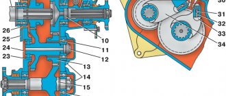
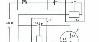
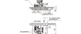
The diagram of the hydraulic drive of a single-plunger lift is shown in the figure. Oil from tank 2, through the suction valve with filter 1, is supplied by pump 4, driven by electric motor 3, into cylinder 12 of plunger 11 of the lift. When the pump is running, using handle 9 of control valve 6, oil can be directed into cylinder 12 through bypass valve 8 (during lifting) or directly into tank 2 (idling). Reducing valve 5 (adjusted to a pressure of 9 kg/cm2), at the moment the plunger stops lifting, automatically transfers oil to tank 2. The oil pressure in the system is controlled by pressure gauge 7. Lowering of the plunger 11 occurs under the influence of the weight of the car mounted on the lift frame 10 when the gear is not working pump. In this case, control valve 6 is set to the “descent” position, and the speed of lowering the plunger is regulated by bypassing oil from cylinder 12 to tank 2 (bypassing the pump) using the handle of bypass valve 8.
Spontaneous lowering of a car raised on a lift is prevented by folding racks attached to the lift frame.
For the hydraulic mechanism, spindle oil or a mixture of 65% AK oil and 35% kerosene is used.
How to install
Before installing a car lift, it is necessary to take measurements of the workshop and calculate the dimensions of the area for the structure. When determining the area, it is necessary to take into account the expected size of vehicles for repair and the space for comfortable work of specialists.
According to standards, a distance of 1 m must be maintained between the lifting structure, wall panels and other equipment. The length of the workplace depends on the dimensions of the machines. For passenger cars, it is enough to allocate a space of up to 7 m; for the repair of off-road vehicles, compact buses, and Gazelles, more than 7 m is required.
When choosing a location for the auto-lifting mechanism, it is necessary to take into account the distance from the sink due to high humidity. It is not recommended to carry out paint work or spray chemicals near the installation. The site should provide convenient access and the ability to move to other repair areas (painting, engine disassembly, etc.). The territory requires sockets for connecting electrical appliances and a sufficient level of lighting for high-quality repairs.
The ceiling level must be taken into account. According to the standards, the height must prevent deformation of the car body, open hood and luggage compartment when raised to the maximum support value. If the ceiling level in the auto repair shop is insufficient, it is necessary to make a recess under the lifting mechanism in which a specialist can perform work.
In compact auto repair shops, equipment is installed “on the floor”. A recess is made in the floor covering (to fit the dimensions of the assembled lift). Installation is carried out when the structure platform is level with the floor.
In the absence of repair work, the site can be used as a parking lot for other types of maintenance (cleaning, painting, etc.). The hidden installation method requires a concrete foundation.
To work you need:
- construction level (manual or laser);
- electric drill;
- drills for concrete surfaces;
- wrench (torque);
- screwdrivers of different diameters;
- wrenches;
- hammer, etc.
Before installation, it is necessary to mark the fixation points of the supports. Holes are made with an electric drill for fasteners (anchors). The standard size of openings according to standards is about 12 cm; anchor bolts are selected to match the size of the openings. Surfaces must be cleared of construction debris; blowing is carried out with a pneumatic gun.
When installing structural supports, the anchor bolt is installed through the steel base into the concrete base and driven in with a hammer. The nut must be tightened with a torque wrench. The tightening torque must be taken into account according to the parameters specified in the instructions.
Then the supports are placed vertically, and the symmetry of the placement of the posts is checked using a measuring level. When connecting parts, it is necessary to firmly tighten the fasteners (nuts, screws).
When installing supports, the location of the operator, who controls the actions of the lifting mechanism, is taken into account. There must be enough space for the specialist so that when lowering and raising the machine, doors and elements do not harm the operating personnel. If there is a block with extension in the design of the car lift, the supports are installed at a greater distance.
The next step involves connecting the device to an electrical power source and commissioning. For car lifts, voltage parameters vary from 220 to 380 V. For models equipped with a pneumatic drive, access to a source of compressed air is required. Therefore, it is necessary to supply main pipes to the installation site of the structure. The pressure in the installation must correspond to the manufacturer's recommendations.
After installation, the hydraulic cylinder of the structure is filled with oil, and the moving parts are lubricated with machine oil. Power is supplied and the equipment is tested first without load. It is necessary to perform a series of lowering, turning, and lifting to check the smoothness of the device and its operating speed. Noise during operation of the device is unacceptable. After testing the equipment with the vehicle, you can begin to work.
Electromechanical lift
The group of electromechanical lifts includes:
- stationary screw four-post lift for trucks and buses
- two post lift for passenger cars
Rice. Electromechanical four-post lift GARO model 448
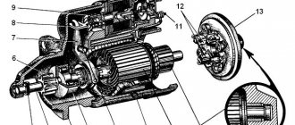
In a four-post lift, inside the posts 8 there are screws 4, on which the lifting frame 5 is suspended using nuts 3. Each screw is driven by an independent electric motor 1 through a worm gearbox 2.
To hang the car wheels, a lifting trolley 6 with jacks 7 is used. The lift frame is raised and lowered by four synchronous electric motors with reversible magnetic starters. The lift's lifting capacity is 7 tons; the total power of electric motors is 11.2 kW.
Rice. Electromechanical two post lift
Scissor lifts
Perhaps the most functional lifting devices today, characterized by maximum ease of operation, small dimensions, good load capacity and low price. In this design, the hydraulic drive drives the lever system, which is shaped like scissors; moving along special grooves towards each other, they thereby straighten and lift the working platform with a load:
- the matter is rarely limited to scissors alone, since they often cannot provide the required lifting height - for example, when storing goods on the upper shelves of shelving structures. Lifts with two, three, four and five scissors are manufactured especially for this purpose, which can operate at significantly higher heights, although with less reliability. As for reliability, there are designs with a parallel arrangement of scissors (for lifting one or even several platforms), the use of which, although not conducive to working at height, provides additional stability and load-carrying capacity of the device;
- Scissor lifts can also be stationary or mobile. Stationary ones are mounted directly into the floor for long-term use in one place - for example, servicing a specific loading and unloading area. Mobile ones - they are also called hydraulic carts - can quickly move around the enterprise, which is especially convenient when there are a large number of work areas or extended storage systems.
Scissor lift
We recommend to buy
More on the topic: How to choose a picanisque lift?
Two Post Portable Lift
A two-post portable lift, designed for lifting Volga and Moskvich cars, has a lifting capacity of 2 tons. The portal-type frame consists of two vertical posts 1 with inclined adjusting struts 7 and cross members 2. Inside the vertical posts there are lifting screws, which are connected by means of nuts carriages 8 are suspended with beams 9 attached to them using pins with grabbers 10. Beams 9 can be rotated on the pins in a horizontal plane.
The lifting screws are driven by one electric motor 6 with a power of 2.8 kW through two worm gears 3 and 5 and a cardan transmission 4. In the extreme upper and lower positions, the carriages 8 are stopped by the limit switches of the electric motor. Lifting height 1.5 m, full lifting time 1.5 min.
The lifts discussed above, compared to ditches of any type, have the advantage that work on the bottom of the car is carried out from the floor level of the room under normal hygienic conditions and there is good access to the lower parts of the car. The exception is the single plunger full rotation lift.
In addition, lifts are universal (within the limits of their load capacity), provide simultaneous suspension of vehicle wheels and occupy a relatively smaller area compared to ditches (taking into account maneuvering areas).
Disadvantages of lifts include the inability to simultaneously work above and below the vehicle, increased initial and operating costs, and some deterioration in the safety of working under the vehicle compared to ditches.
Rice. Electromechanical four-post lift with rising working platforms: 1 - fixed platform; 2 - rising platform; 3 - lifting platform; 4 - stand
In foreign practice, four-post electromechanical lifts with working platforms that rise together with the lifting platform are used to work on top of the car, which eliminates one of the above-mentioned disadvantages of lifts.
Main varieties
The hydraulic lift at the manufacturer's price is presented in the catalog with various devices. Depending on the type of lifting element, hydraulic lifts of the mast type and scissor type are distinguished. The greatest demand is for scissor versions, which have increased stability, reliability and ease of use. Manufacturers offer units that differ in design, technical parameters and application possibilities:
- Bottle (models HV6, HV12, HV30, HV50) with a lifting capacity of 6-50 tons
- Roll-on (models HF, HF) with a lifting capacity of up to 2-3 tons
- Low-roll (models TG and NM) with a lifting capacity of 3-8 tons and 5-25 tons
Bottle lifts are light in weight and have a simple design; they are used in mechanical engineering, construction, and auto repair shops. Roll-away models are mainly in demand in car repair shops and service stations. Low-rolling lifts are indispensable in installation, rigging, and repair work with heavy loads. All devices are equipped with a security system that meets the requirements of European and domestic standards. Hydraulic lifts from well-known manufacturers are wear-resistant and can be used indoors and outdoors.
Electromechanical lift-tilter
The electromechanical lift-tipper shown in the figure allows you to tilt the car at various angles, but not more than 60°.
Rice. Electromechanical tipper: 1 - stand; 2 — lifting frame; 3 — car fastening clamp; 4 - carriage; 5 - fixed frame
The lifting frame is driven by an electric motor with a worm gear and a screw with a nut located in the rack. When using a tipper, you must first remove the battery from the vehicle and seal the holes in the master brake cylinder and the neck of the engine crankcase and fuel tank.
Car lifts. Device and principle of operation
Lifts are used to raise vehicles above the floor level during maintenance and can be stationary, mobile or portable.
According to the type of lifting mechanism, lifts are divided into:
- mechanical
- pneumohydraulic
- hydraulic
By type of drive:
- manual
- electric
- powered by car engine
According to the design of the supporting part, lifts are:
- with track frame
- with inter-track frame
- with cross frame
- with support beams
Schematic diagrams of plunger-type hydraulic lifts are shown in the figure.