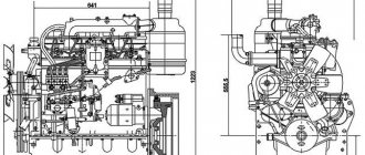
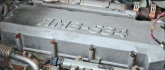
Engine MMZ D-240
MMZ D-240 belongs to 4-cylinder diesel engines, the cylinder block is reinforced, made of cast iron, the engine capacity of the D-240 is 4.75 liters.
The power plant is naturally aspirated, characterized by increased reliability and simplicity of design. The motor is easy to repair; the procedure is possible even in the field. Since the power plant is diesel, the fuel supply is injection, the engine is provided with the necessary thrust and sufficient power. The design solution was to use an undivided type working chamber on the engine. In addition, there is double fuel injection, with the formation of working fluid vapors by volume and distribution of the fuel in the form of a film over the cylinder and piston.
High-strength gray cast iron helps the cylinder block of the power unit avoid thermal deformation. The material made the motor heavy, the weight of the MMZ D-240 engine is 430 kg, this justified itself, since the motor does not have diseases inherent in similar mechanisms.
Specifications
| Cylinder block material | cast iron |
| Supply system | Direct injection |
| Type | in-line |
| Working volume, l | 4.75 |
| Power, l. With. | 80 |
| Number of cylinders | 4 |
| Number of valves per cylinder | 2 |
| Piston stroke, mm | 125 |
| Cylinder diameter, mm | 110 |
| Compression ratio | 16 |
| Fuel | Diesel fuel |
| Fuel consumption | No more than 238 liters per hour |
Engine cooling system D-240
The D-240 is equipped with closed-type liquid cooling, so the motor is used on the MTZ-80 and MTZ-82 tractors. The closed type of cooling is quite a bold solution, because contact with the environment occurs for a split second and only through the valve. In order not to overheat the engine, the fluid must be at the optimal temperature, which ranges from 80-97 degrees. This indicator is monitored by a thermometer; it is possible to manually adjust the temperature.
Source
Engine D-240 of the MTZ-82 tractor: design, repair and characteristics
The MTZ-82 tractor is equipped with a four-cylinder, four-stroke diesel engine D-240 with an electric starter (D-240L with a starter). Engine power is 59 kW or 80 hp.
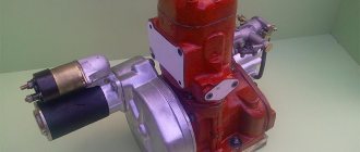
Engine photo
Engine device
The D-240 engine has an undivided combustion chamber with volume-film formation of the working mixture. One part of the injected fuel is sprayed into the volume of the combustion chamber, and the other spreads over its surface, creating a thin film. The first part of the diesel fuel is actively mixed with the flow of heated compressed air, and intense evaporation and combustion occurs - the process of preliminary ignition of the fuel occurs. The tent shape of the combustion chamber promotes the formation of turbulence in the air flow and better mixing of air and fuel. Part of the fuel, in the form of a film, evaporates, heating up from the flow of compressed hot air and the wall of the combustion chamber. The gradually created process of fuel combustion creates the conditions for soft, economical operation of the engine.
Like any similar diesel engines, the D-240 engine consists of a gas distribution (GRM) and crank mechanism (CVM), as well as systems: cooling, lubrication, starting and power.
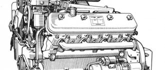
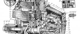
D-240 engine diagram: 1 - flywheel; 2 — breather; 3 — cylinder head gasket; 4 — cylinder head; 5 — cylinder head cover; 6 — rocker shaft; 7 — valve spring plate; 8 — exhaust valve; 9 - suction valve; 10 — valve spring; 11 — rocker shaft support; 12 — valve rocker arm; 13 — cover cap; 14 — rod; 15 — cylinder block; 16 — valve pusher; 17 — distribution board; 18 — distribution cover; 19 — adjusting bolt; 20 — shock absorber with limiter; 21 — front engine support; 22 — cuff; 23 — oil pump drive gear; 24 — crankshaft camshaft gear; 25 — timing gear; 26 - camshaft; 27 - crankshaft; 28 — connecting rod; 29 — counterweight; 30 — piston pin; 31 - piston; 32 — sealing ring of the sleeve; 33 — oil pan; 34 - cuff; 35 — cylinder block liner; 36 — back sheet; 37 - bushing.
Specifications
| Type | diesel four-stroke water-cooled |
| Model | |
| D-240 with electric starter | |
| D-240L with starting engine | |
| Power, kW (hp) | 59(80) |
| Rotation speed, rpm. | 2200 |
| Number of cylinders | 4 |
| Cylinder diameter | 110 |
| Piston stroke, mm | 125 |
| Compression ratio | 16 |
| Volume D-240, l | 4,75 |
| Cylinder operating order | 1-3-4-2 |
| Fuel consumption, g/kW*h (g/els*h) | 238(185) |
| Fuel pump | Four-plunger with booster pump |
| Engine weight, kg | D-240 - 430 |
| D-240L - 390 |
Cylinder block D-240
The main part of the engine housing, which is a rigid casting made of gray cast iron, is the cylinder block. Engine parts, mechanisms and assembly units are installed inside and outside the block. For their installation, special seats, holes and planes are provided.
Four cylinder liners are mounted in the vertical bores of the block, sealed at the bottom with rubber rings. In the axial direction, the liners are secured using collars in the bores of the upper plate of the block. The sleeves are made of alloy cast iron, the elements of which (copper, chromium, nickel, chromium) significantly increase the wear resistance of the working surfaces of the sleeve. The cylinder mirror (inner surface of the liner) is not hardened.
The upper part of the cylinder block is divided into four cavities by three transverse vertical partitions. Coolant circulates through these cavities, entering all cavities through a side water channel through holes opposite each liner. The volume between the sleeves and the walls of the block acts as a water jacket. The walls of the cylinder block are made in the form of arches, supported by inter-cylinder partitions. Thanks to this, a water jacket of equal thickness is created around the entire perimeter of the sleeve and the temperature difference around the circumference of the sleeve is reduced.
In three vertical partitions, as well as in the rear and front walls of the block, beds for the crankshaft main bearings are made, closed with covers. To ensure uniform tightening of the bed covers, hardened washers are placed under the bolt heads. Rearranging and replacing the covers is not allowed, since they are bored together with the main bearing beds with very high precision. In order to prevent incorrect installation of the main bearing caps, various distances are provided from the axis of the bed boring to the holes for the bolts in the caps.
In the rear and front walls, at the top and right of the crankcase part of the cylinder block and in the middle partition, holes are made in the bosses for installing camshaft bushings. These bushings are bored after being pressed into the block.
The cylinder block has a longitudinal oil channel through which engine oil flows to each main bearing and to all camshaft journals. The longitudinal channel is connected to the oil filter using a horizontal transverse channel. In the drillings of the vertical columns of the right outer wall of the block, pusher rods are placed, resting with the lower spherical end on the pushers.
Depending on the type of trigger mechanism, one of two versions of the rear sheet is installed in the rear part of the cylinder block, differing in size and coordinates of the centering hole. There is a threaded hole in the wall of the rear sheet into which a special probe (screw) is screwed in, which is necessary to set the start of fuel supply to the first cylinder of the engine. To mount the flywheel, there is a hole in the middle of the rear plate through which the crankshaft flange passes. The clutch housing is attached to the outer holes of the sheet, centered using two pins pressed into the housing flange.
Bolted to the front of the cylinder block is a distribution board made of rolled sheet metal and a distribution cover made of gray cast iron. Their uniform centering is ensured by two pins pressed into the front wall of the block. Precision machined holes in the switchboard ensure correct mounting of the oil and fuel pumps, as well as proper meshing of the drive gears. The front engine mount is adjustable and is secured with two bolts to a lug at the front top of the distribution cover. Distribution gears are located in the cavity between the cover and the shield.
Cylinder head of the D-240 engine (cylinder head)
The cylinder head is installed on the cylinder block and secured with sixteen studs. The stud nuts are tightened with a torque wrench in a certain order. A special asbestos steel gasket is placed between the surfaces of the head and the block. The internal cavity of the head acts as a water jacket. The coolant coming from the cylinder block is directed through channels to hotter places: jumpers between the injectors and valves. The valve mechanism and head cover are installed on the top of the cylinder head, to which the cover cap with breather and the intake manifold are attached. At the bottom of the head there are sockets for the exhaust and intake valves. Above these sockets, valve guides are pressed into the channels.
The procedure for tightening the head D-240
Oil sump
The crankcase is made of aluminum in a box shape that is attached to the bottom of the cylinder block and distribution cover. The oil pump oil receiver is located in the front recessed part of the crankcase.
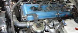
Installation of the D-240 engine on the MTZ-82 tractor
Installation of the engine on the tractor must ensure its reliable fastening, correct placement and damping of frame vibrations. The engine, installed on the tractor half-frame, is attached at the back to the frame, and at the front to the half-frame beam using a front suspension, consisting of a rubber-metal shock absorber and a support. The shock absorber is made in the form of a rubber cushion with a pair of vulcanized plates, with the help of which it is attached to the distribution cover bracket and the front support. The rubber shock absorber significantly reduces the level of vibration of the tractor frame and engine. When installing the engine on the tractor in order to reduce vibrations, it is necessary to perform the following operations to adjust the front suspension:
1. Unscrew the two bolts securing the shock absorber to the protrusion of the cover bracket by 3-4 turns; 2. tighten the bolts securing the front engine mount to the front beam; 3. loosen the locknut and screw the adjusting bolt into the projection of the distribution cover until it stops against the upper plate of the shock absorber; 4. screwing in the adjusting bolt 1.5-2 turns (2-3 mm), compress the shock absorber until its height is 39-40 cm; 5. place the required number of steel shims 0.5 mm thick in the gap that appears between the top plate of the shock absorber and the protrusion of the bracket; 6. Unscrew the adjusting bolt 3-4 turns and lock it with a lock nut; 7. Screw in the bolts securing the shock absorber to the bracket until they stop.
Front suspension of the D-240 engine: 1 — shock absorber; 2 - gaskets; 3 - lock nut; 4 — adjusting bolt; 5 — bolt securing the shock absorber to the bracket; 6 — cover bracket; 7 — front support.
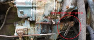
Engine malfunctions
| Air in the fuel system | Bleed the system with a manual pump. If necessary, eliminate air leaks |
| Fuel pump faulty | Remove the fuel pump from the diesel engine and send it to a workshop for repair |
The engine does not develop power
| There is no full fuel supply due to misadjustment of the fuel pump control rods | Adjust control rods |
| The filter element of the fine fuel filter is clogged | Replace filter element |
| Faulty injectors | Identify faulty injectors, clean and adjust |
| Incorrect fuel injection advance angle | Set the recommended injection advance angle |
| Engine air cleaner clogged | Perform maintenance on the air purifier |
The engine smokes in all operating modes
A. Black smoke is coming from the exhaust pipe.
| Air cleaner clogged | Maintain the air purifier |
| Injector needle stuck | Identify the faulty nozzle, wash or replace the nozzle, adjust the nozzle if necessary |
| Poor fuel quality | Change fuel |
| Fuel pump faulty | Remove the fuel pump from the diesel engine and send it to a workshop for repair |
B. White smoke comes out of the exhaust pipe
| The engine is running undercooled | Warm up the diesel engine, maintain the coolant temperature within +75-95°C during operation |
| The gaps between the valves and rocker arms are not adjusted | Adjust the gaps |
| Water getting into fuel | Change fuel |
B. There is bluish smoke coming from the exhaust pipe.
| Oil entering the combustion chamber as a result of wear of parts of the piston liner group | Replace worn parts of the sleeve-piston group |
| Excess oil in the crankcase | Drain excess oil by setting the level to the top mark of the oil dipstick |
MTZ-82 engine gets hot
| Coolant boils in the radiator | Eliminate coolant leaks from the cooling system, clean the radiator from dirt and dust, if necessary, descale the cooling system, adjust the fan belt tension |
| Fuel atomization by injectors has deteriorated | Identify faulty injectors, rinse, clean and adjust |
No oil pressure on warm engine
| Pressure gauge faulty | Replace |
| The tightness of the oil pipe connections is broken | Identify and repair |
| The lubrication system pump is faulty | Fix the problem or replace the pump |
| The oil level in the crankcase is below the permissible level | Add oil to the top mark |
| Centrifugal oil filter drain valve stuck | Flush the valve and adjust the pressure |
| Limit wear of the crankshaft journal-bearing interfaces | Send the engine for repair |
MTZ 240-1002001-B2 cylinder block for the MTZ-80/82 tractor.
Cylinder block MTZ 240-1002001-B2
The D-240/243 cylinder block is installed on tractors: MTZ-80, 82, 82.1 and their modifications. Cylinder block 240-1002001-B2 , for the four-cylinder D-240 engine, used to rebuild the engine on the MTZ-80 tractor; MTZ-82; 82.1. It is a one-piece part that unites the engine cylinders. Cast from cast iron. The cylinder block has supporting surfaces for installing the crankshaft; the cylinder head is usually attached to the top of the block; the bottom part is part of the crankcase. Thus, the cylinder block is the basis of the engine on which the remaining parts are hung. In addition to the formative part of the engine, the cylinder block has additional functions, such as the basis of the lubrication system - oil under pressure is supplied through holes in the cylinder block to the lubrication points, and in liquid-cooled engines the basis of the cooling system - liquid circulates through similar holes throughout the cylinder block.
Device
Separately, it is worth considering the structure of the tractor, as well as its main elements.
Transmission
All versions of this tractor are equipped with a 9-speed gearbox, additionally equipped with a reduction gearbox. In total, this provides 18 forward gears, as well as 4 reverse gears. Additionally, as an option, it is possible to install a creeper in situations where the work requires it. When knocking noises appear during the operation of the gearbox and disappear in other gears, this indicates misalignment of the teeth due to the destruction of the gears. Certain models produced after 1985 were equipped with a hydraulically controlled gearbox. This made it possible to switch speeds without stopping work and made it possible to select a new gear in 4-range increments without removing the clutch.
Be sure to read: Tractor MTZ 92p
Chassis
It is worth noting here that the MTZ-80 was equipped with a balancing axle, which had a special semi-rigid suspension that allows the wheels to take the desired position. But the rear wheels are mounted with terminal connections directly to the drive axles. Due to this, they are able to change the track width within a specified range. Disc brakes are installed on the tractor. To make it easier to turn the steering wheel, power steering is used, which works on a similar principle to automobile versions.
Belarus tractor engine
Cabin
The MTZ-80 model is equipped with a cabin made of thin sheet steel. In this case, internal lining is carried out for the purpose of insulation, as well as sound insulation of the driver's seat. Fastening to the frame is carried out using 4 rubber shock absorbers, which reduce shaking and vibration during operation. The driver has good visibility due to panoramic windows, as well as the presence of wipers for cleaning the front and rear windows. In order to ensure air flow, it is possible to open the roof or rear window by locking it in this position. The steering column in the tractor can be adjusted in several planes at once.
For operation in the cold season there is a heating system.
MTZ engines: D-260, D-245, D-240
Engine D 260
Diesel engines D-260 and their modifications are 4-stroke, piston, six-cylinder internal combustion engines, with a single-row, vertical cylinder arrangement, equipped with a direct fuel injection system and ignition of the fuel mixture from compression.
The D 260 engine and their modifications are used as power units for energy-rich wheeled tractors and road construction equipment.
Technical characteristics of D-260
| Parameter name | D-260 |
| Type | four-stroke turbocharged |
| Number and arrangement of cylinders | 6, in-line, vertical |
| Working volume, l. | 7,12 |
| Cylinder diameter and piston stroke, mm. | 110/125 |
| Compression ratio | 15 |
| Specific fuel consumption, g/kW•h (g/hp•h): | 220 (162) |
| Power, kW (hp): | 114 (155) |
| Rotation speed, rpm: | 2100 |
| Maximum torque, N•m (kg•m): | 622 (63,5) |
| Rotation speed at maximum torque, rpm: | 1400 |
| Weight, kg: | 700 |
Reliability, problems and repair of MMZ D-243
Production of the D243 diesel engine at the plant in Minsk began in 1974, and it was an in-line 4-cylinder engine. A cast iron cylinder block with wet cast iron liners is used here; inside this block there is a steel crankshaft with a piston stroke of 125 mm, with main journals of 75.25 mm and connecting rod journals of 68.25 mm. Steel connecting rods 230 mm long, aluminum pistons 110 mm in diameter with piston pins 38 mm in diameter. This provides a working volume of 4.75 liters. The oil pressure at MMZ D-243 should be in the range of 2.5-3.5 kgf/cm2.
A cast iron head with 2 valves per cylinder is installed on top of the block. The diameter of the intake valves is 48 mm, and the exhaust valves are 42 mm, the thickness of the stem is 11 mm. This is a bottom-mounted motor; accordingly, the camshaft is located in the block and drives the valves through pushers, rods and rocker arms. The valves should be checked and adjusted every 500 hours of operation. The valve clearances are as follows: intake and exhaust - 0.25 mm. The order of valve adjustment is the same as the operating order - 1-3-4-2.
For these engines there is a 4UTNI fuel pump. Based on the 243, the famous turbodiesel D-245 was created.
Modifications of D-243 and their differences
1. D-243 - regular version with 81 hp. 2. D-243L - the same D-243, but with a different exhaust manifold. 3. D-243.1 - 83 hp motor. 3. D-243.2 - version for mining vehicles with a power of 60 hp.
Malfunctions D-243
This is a simple engine without supercharging and additional electronics and, accordingly, it does not have many of the problems inherent in turbocharged D-245 diesel engines. In any case, age takes its toll, and if you have problems with smokiness, as well as other joys, then the reasons for their occurrence are described here.
Tuning of D-243 engines
Turbine installation
You can convert your naturally aspirated 243 into a turbocharged D-245, thereby adding some power to it. To implement this, you need a TKR 6 turbine from the 245, an exhaust manifold for it from the D-245, make an oil supply and oil drain, configure your fuel injection pump and everything will work on standard pistons. For this purpose, ready-made turbine installation kits are sold for quite reasonable money. You can’t get a full-fledged D-245 this way (the block, crankshaft and pistons are different), but you will add power to the engine.
<<BACK
Description
This is a classic four-cylinder modification of a diesel engine, which has a reinforced cylinder block, and thanks to the presence of air cooling, its design is significantly simplified. This naturally aspirated power unit is highly reliable and easy to maintain. Its maintainability allows repairs to be carried out even in the field.
Due to the presence of direct fuel injection, the engine provides the necessary traction and excellent power characteristics. The motor has an electric starter, which significantly simplifies the operation of the MTZ-80 tractor in the winter, when problems with starting a diesel engine could be observed.
Another design feature of this engine is an undivided combustion chamber, as well as the formation of a volume-film working mixture. In this case, the inlet of the fuel mixture into the combustion chamber is carried out as follows. Part of the fuel is sprayed into the maximum possible volume of the combustion chamber, while the other part spreads over the surface of the cylinder, creating the necessary thin film. As a result of such technologies, the maximum possible power and efficient combustion of fuel are ensured, which has improved the dynamic characteristics of this power unit.
The combustion chamber itself has an original spherical shape, which improves the mixing of air and fuel, forming vortex air flows inside the combustion chamber. The power of the D 240 engine is 80 horsepower, which is achieved at 2200 crankshaft revolutions per minute. At the same time, the engine is characterized by proper throttle response, guaranteeing the tractor the necessary power and traction.
The D 240 cylinder block was cast from high-strength gray cast iron. The use of such material allows you to completely avoid the occurrence of thermal deformations of the power unit when the engine overheats. The cylinder head is attached to the block using 16 extended studs. It should be said that the studs were tightened using a torque wrench, which must be taken into account when performing repair work.
Note that this modification of the engine used a special design of the valve mechanism, which made it possible to protect the valves in the event of a timing chain break. This increased the reliability of the engine, and the engine itself could be operated for a long time without the need for major repairs.