What is an MTZ electrical circuit?
Let's look at what the electrical equipment diagram of a Minsk tractor consists of. One of the advantages of Minsk technology is the use of high-quality electrical wiring, based on the fact that metal parts are designed to act as mass. The advantages of such electrical wiring MTZ-1221, 80 or 82 include:
- reduced number of wires;
- simplified approach to maintenance.
But you need to take into account that wiring requires constant care and monitoring.
This will help monitor the serviceability of the wires, their insulation, and the reliability of the fastenings. If damage to the electrical circuit of the MTZ-80 or 1221 tractor is not detected in time, a fire, insulation damage, failure of electrical circuits, etc. may occur.
Let's look at the electrical equipment of Belarus tractors and a description of its operation.
The electrical circuit of MTZ-1221, 80 or 82 has the following characteristics:
- It has a polyvinyl chloride colored surface with low voltage.
- Additional elements are connecting panels, connectors, and wires that can be mounted in bundles. For example, such a half-move is applied to wires in MTZ-82.
- The PS 300A-100 socket is located on the rear wall of the operator's cabin and has 7 contacts.
- The socket is intended for all work where electricity is needed, including when transporting goods.
- Connection to the socket is made via a plug.
- If the need arises, you can connect the wiring harness from other units. Both the plug and the socket have special markings that help you understand where the wires are connected.
Thus, the wiring of MTZ-80, 82 and 1221 is functional and is designed to withstand loads while the tractor is operating.
Converters MTZ 1221, 80, 82 – parameters PN 15 A 12-24
The device weighs no more than 0.5 kg. Designed for use at 10 to 80 degrees. It is not recommended to exceed this heating temperature. Remember that if the device does not work, most likely the connection of the MTZ 80 voltage converter was made incorrectly.
Check the battery connection diagram more carefully.
Modern PN 15 A 12-24 devices are usually installed in electrical circuits to charge batteries as quickly as possible. As a rule, the car engine is started by the starter. There is a voltage of 12 volts here.
The maximum current consumption is also 12 Volts. If you connect a voltage converter MTZ 80 model PN 15 A 12-24, remember that the device measures the incoming current at 13.5 V with a power of 12 Amps.
An output power of 8 Amps is observed at 24 V.
Voltage converter MTZ PN 14-28 V-8A – features
The PN 14-28 V-8A device is used to quickly charge a 24 Volt battery. It has a durable body and is made of the most reliable materials. Weighs about 0.5 kg. For ease of installation and delivery it has a compact size.
Efficiency – 88%. If the connection of the MTZ 80 voltage converter is made with an error, or the current exceeds 8 Amperes, the device turns off automatically.
Also, the device does not work if there is a short circuit or the output voltage is exceeded.
How to connect a voltage converter MTZ 80?
Below we will publish a photo of the connection diagram PN 14 (141).3759-RK.
However, do not forget that before connecting the device, you need to read the manufacturer’s recommendations, as well as study the technical characteristics of the modern device.
Electrical wiring diagram of MTZ-82.1, color with description
"Belarus" MTZ-82.1 is a new universal agricultural tractor of 2006, which is a modified model of MTZ-82 and can be equipped with a hole drill, hay thrower or plow. In models produced since 2013, the chassis has been improved and a large number of attachments have been added, which can be purchased separately.
When performing electrical equipment maintenance or repairs, most often the required unit is removed or the wiring is partially disconnected; this is where you will need a schematic diagram of the electrical wiring in color, which you can view and download absolutely free!
If you need to disconnect or connect electrical wiring, repair equipment (for example, a generator or battery):
- check the electrical diagram;
- turn off the main switch before starting work (disconnection and connection of plugs should be carried out strictly when the engine is not running);
- do not check the serviceability of electrical circuits using the “spark” method, creating a short circuit;
- Observe the polarity of the battery, carefully connect plus to plus, minus to minus.
Electrical equipment MTZ-80 with a small cabin
The Belarusian tractor MTZ-80 with rear-wheel drive and a small cabin is equipped with DC electrical equipment. All devices are connected “plus” to each other according to the circuit with one wire, the negative terminals “cling” to the ground of the tractor. In the picture you see a color wiring diagram of the old 1974 model.
Let's consider its main elements:
- Battery, generator, relay regulator.
- Electric starter, torch heater and switch.
- Headlights: front and rear, turn signals with turn relays, side lights, brake lights, cabin light, light switches.
- Electric motor of the air conditioning and heating unit.
- Windshield wipers and switches with separate electric motor.
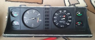
- Measuring instruments. If you did not know how to connect an ammeter to the circuit, then it is already installed between the power source and the generator.
The electrical diagram of the MTZ-82 with a large cabin, shown in the photo, helps the user understand the location of electrical equipment and the cables that connect them. Separate colored callouts decipher the purpose of a particular wire based on the color of the protective insulation.
MTZ-82 tractors with a large cabin of the new generation, which began to be produced in 2010, have some additions to the electrical circuit: a circuit for connecting a radio with the ability to turn on when the engine is not running, as well as an air conditioner with a compressor.
Maintenance of devices at MTZ
To ensure that the controls and the generator itself do not fail, it is better to carry out regular maintenance.
First of all, it is necessary to regularly remove the oil and dust that settle under the lid. It is better to blow off the dust with a compressor, but ordinary rags will do. If dirt has clogged the cracks, disassembly and wiping will be necessary. You need to do it with the same rag soaked in gasoline. You should not use cotton wool or synthetics for cleaning.
You need to regularly inspect the terminals for oxides. As soon as they appear, they must be removed mechanically with sandpaper or a file. You should act carefully, just to remove the oxide film. You can also lubricate the contacts with copper or silicone grease.
Inspect the impeller and pulleys periodically. Any cracks or chips indicate an imminent major overhaul. It is better to replace them immediately to avoid emergency situations. Likewise, it is recommended to check the belt tension.
After connecting the generator and the engine has been started, look at the warning light. It should go out immediately. On some MTZ tractors, idle flashing is normal if the rotation has not reached 1.4 thousand revolutions.
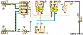
Connection diagram for generator MTZ-80
The generator on the Belarus MTZ-80 is installed as a three-phase one, in the rectifier of which the alternating current is converted into direct current. It serves as an additional source of electricity, along with batteries.
The colored electrical circuit of the generator shown in the picture with a description consists of:
- series-installed coils and stator field windings;
- rectifier unit consisting of a diode bridge;
- regulator unit with voltage switch.
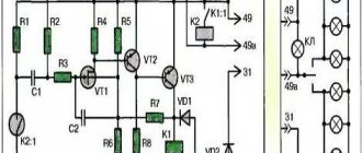
Ignition switch MTZ-82 wiring diagram
The ignition switch block is installed on the dashboard and is used to start the starter of the tractor starting engine. Starts or interrupts the operation of a current-carrying circuit. Main parts of the ignition switch 2:
- a switch on which the output terminals and the main contact with the generator rotor are located;
- a lock, which in turn consists of a zinc body, retaining rings, locking cylinders and a key.
The wires must be connected according to the color diagram.
Signs of stator winding malfunction
To begin with, it would be nice to know what connections are used for this device. This is a simple matter: the negative wire of the battery is attached to the “M” terminal of the generator, and the positive wire is connected to the “W” terminal through a test lamp.
- As mentioned above, if the winding is faulty, the indicator light on the dashboard will not light up, or will light up very weakly. In addition, the current strength will not exceed 3-3.5 amperes.
- If the light does not light up at all (regardless of the modification of the tractor engine), then the winding is simply torn, rotted, or oxidized (it must be emphasized).
- We change the connection. We throw the minus terminal of the battery onto any terminal of the generator, and the plus terminal again through the indicator light to terminal B of the generator.
Charging circuit MTZ-80
This color diagram with a description shows what elements the charging system of the MTZ-80 tractor consists of.
- Generator, which is the main power source.
- Rechargeable lead-acid batteries act as a backup power source for the tractor engine.
- An indication lamp that lights up when the generator does not produce electric current when the ignition switch is turned on.
- A fuse box that protects an electrical circuit from a short circuit.
The generator and battery are connected with a “positive” wire, and the “minus” wire is output to the metal case.
Checking proper operation
To be confident in the unit you are using, it is advisable to check its functionality before each use. For this purpose, a special control lamp is used. When the tractor ignition is activated, it should light up, and when the engine starts successfully, it should go out immediately.
The lamp can only turn off after increasing the crankshaft speed. If this does not happen, we are talking about the presence of malfunctions in the operation of the generator. To do this, turn off the engine and then follow the following instructions:
- Check the tension level of the alternator belt and adjust it if necessary.
- Connect the negative wire from the battery to terminal “M” and the other to terminal “B”.
- Turning on the lamp at this stage indicates a malfunction of the rectifier.
- Next, the “-” from the battery will need to be connected to the AC terminal, and the “+” to the “B” terminal. If the lamp lights up, the rectifier diode is broken down.
You can also combine the “+” from the battery with the AC terminal, and the “-” with the “M” of the generator. When the lamp is turned on, the problem most likely lies in a short circuit in the stator winding or a broken diode.
Care should be taken when working with electrical components, as they can quickly become unusable if not handled correctly.
Electrical circuit maintenance
Maintenance of the tractor circuit can be done with your own hands or with the help of an electrician. The main thing is that this happens regularly and that all terminals and fastenings are checked. If necessary, it is necessary to clean the necessary parts from dirt and dust.
The starter requires cleaning every 3000 hours of use. To do this you need to do the following:
- dismantle the starter;
- remove dirt;
- remove the casing that performs protective functions;
- check the brush-commutator assembly.
Then the starter must be reassembled and the insulation on the wires, the connections on the plugs, and the integrity of the wires checked.
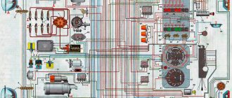
Wiring diagram MTZ 82(80) with large and small cabin with description
Belarus tractors are equipped with single-wire electrical equipment designed to start the engine, operate external light and sound alarms and additional components. The color diagram of the MTZ-82 electrical equipment attached to the technical documentation with a description allows you to determine the purpose of the wiring cables and restore the integrity of the circuits in the event of a breakdown.
Electrical diagram of the MTZ-82 tractor
The electrical circuit has a voltage of 12 V, the negative outputs of current sources and consumers are connected to the metal frame of the tractor. A lead-acid battery and an alternating current generator mounted on a diesel engine are used as current sources. To drive the rotor, a belt drive is used from a pulley on the toe of the crankshaft.
The generator is equipped with a rectifier unit and works in conjunction with a regulating relay, which maintains a stable voltage in the on-board network and turns off the generator winding when the tractor is idle.
On equipment assembled before the beginning of 1976, the G304-D1 installation with a power of 400 W was used. Later, G306 with similar parameters and G309, characterized by increased output up to 1000 W and an increased resource, began to be used. The generators are equipped with a self-excited winding, which allows the equipment to be operated with the battery removed. Factory documentation recommends connecting electrical equipment in series, which reduces the peak load on the generator.
What is
The diagram shows the relative positions of electrical components and connecting cables. A separate field contains a description of the colors of the insulation used to protect electrical wiring. Separate callouts explain the switching of nodes or relays, which simplifies repair work.
The tractor design uses a power switch that allows you to temporarily disconnect the batteries from the vehicle body. De-energization is used during long-term storage of equipment or during routine maintenance related to electrical circuits.
A short list of components available on the wiring diagram of the MTZ-82 tractor:
- power supplies;
- distribution box with fuses;
- control devices and indicators in the operator's cabin;
- electric starter and device control circuits;
- PD-10 gasoline starter ignition system (installed on the MTZ-82L modification);
- external lighting equipment (headlights, side lighting, stern brake signals, direction indicators);
- electric motors of the windshield wiper trapezoid, washer fluid supply pump and ventilation system;
- a plug socket that allows you to connect lighting devices on towed equipment;
- auxiliary devices (for example, a signal beacon on the roof or a lamp in the tractor cabin).
Maintenance and repair
Maintenance of the electrical components of the MTZ-82 tractor consists of carrying out routine maintenance and checking the condition of cables, instruments and incandescent lamps. The batteries are wiped from dust and traces of electrolyte, the liquid level in the banks is checked, and recharging is performed. In the generator, the field windings are checked, as well as the rectifier unit and the windings on the stator.
The voltage regulator used on the tractor is equipped with a seasonal switch. The manufacturer recommends checking and adjusting the voltage value at the regulator output. The unit is configured on equipment or on a special stand.
The electric starter is serviced after 3000 hours of diesel engine operation. The electric motor is removed for disassembly, followed by cleaning the commutator and checking the condition of the brushes. At the same time, the condition of the electromagnetic relay and the gear in contact with the ring gear of the diesel flywheel is monitored.
During operation, contamination of the high-voltage wire running from the magneto to the spark plug is not allowed. The magneto is serviced after 960 hours of engine operation; during the inspection of the unit, the components are cleaned of contaminants and the gaps between the breaker contacts are adjusted. At the same time, the spark plug is unscrewed and the gaps between the contacts are checked.
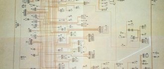
MTZ 80 tractor diagram - car diagrams
Schematic diagram and parameters of electrical equipment of tractors MTZ-80 - 82. The wiring system is single-wire, the negative pole of the current source is connected to ground. Rated mains voltage, V 12. Alternating current generator 46.3701 with built-in rectifier and integral voltage regulator, rated voltage, V 14, rated rectified power of the generator, W - 700, rated rotation speed, rpm 3600. Battery for tractors with a diesel starting system : electric starter 3ST-216A (2 pcs.), starting motor 6ST-50EM (1 pc.). Battery voltage: 3ST-215A, V 6, 6ST-50EM 12. Capacity: 3ST-215A, Ah 215, 6ST-50EM 50. See other diagrams here.
Electrical diagram of the MTZ 80 tractor
Designation of elements in the diagram:
1 - headlight 2 - front turn signal 3 - water temperature indicator sensor 4 - connecting panels 5 - instrument panel plug connectors 6 - sound signal 7 - relay regulator 8 - MTZ 80 generator 9 - air heating-cooling unit switch 10 - electric motor heating-cooling unit 11 - dome switch 12 - dome light 13 - windshield wiper switch 14 - electric motor with windshield wiper 15 - tachometer speedometer of the MTZ 80 tractor 16 - control lamps for turning on the "ground", high beam and turn indicators 17 - additional resistance 18 - electric torch control element heater 19 - headlight light switch 20 - instrument lighting lamps 21 - torch heater and starter switch 22 - windshield washer 23 - central light switch 24 - stop switch 25 - MTZ 80 taillight 26 - taillight 27 - connecting panels 28 - switch rear headlights 29 - instrument panel plug connectors 30 - power socket 31 - license plate light 32 - windshield washer switch 33 - turn signal relay 34 - turn signal switch 35 - ground, high beam and turn signal indicator lamps 36 - horn button signal 37 - ground switch 38 - batteries 39 - portable lamp socket 40 - water temperature indicator 41 - MTZ 80 ammeter 42 - fuse blocks 43 - engine start blocking switch 44 - MTZ 80 starter 45 - starter relay 46 - blocking relay 47 - electric torch heater 48 - starting heater electric motor 49 - starting heater solenoid valve 50 - starting heater glow plug 51 - starting heater switch 52 - starting heater control glow coil 53 - starting heater switch 54 - fuel level indicator 55 - fuel level indicator receiver
Hydraulic grip weight increaser device
The automatic device for hydraulic additional loading of the drive wheels of the MTZ-80 (MTZ-82) tractor consists of an automatic pressure regulator with a charger, a control mechanism and a spring hydraulic accumulator.
The pressure regulator and the control mechanism for the hydraulic traction weight increaser are made in one unit, which is installed in the front part of the cabin next to the distributor.
Rice. Design of the hydraulic adhesion weight increaser: 1 - body; 2 - large plunger; 3 - safety valve; 4 - spool; 5 — safety valve spring; 6 - nut; 7 - small plunger; 8 — adjusting spring; 9 — figured nut; 10 - bolt; 11 — adjusting bolt; 12 — front cover; 13 - sealing ring; 14 — handwheel; 15 — outer lever; 16 — internal lever, 17 — axis of levers; 18 - separator; 19 - ball; 20 — clamp clip; 21 — slider spring; 22 — slider; 23 — shut-off valve ball; 24 — shut-off valve spring; 25 - fitting; 26 — valve pusher; 27 — back cover; 28 - check valve.
The hydraulic traction weight increaser for the MTZ-80 (MTZ-82) tractor consists of a housing 1, cast from cast iron and closed on both sides with covers 12 and 27. In the upper part of the housing 1 there is a spool 4, loaded with a spring 8 and moving along the axis along a large plunger 2 The tension of the spring 8 is adjusted using a nut 9. A safety valve 3 is installed inside the spool, pressed to its seat by a spring 5, the tension of which is regulated by a small plunger 7, moved along its axis together with a shaped nut 9 when the adjusting bolt 11 is rotated by a flywheel 14. Safety valve 3 is adjusted so that it opens at a pressure exceeding 0.8–1.5 MPa (8–15 kgf/cm2) the pressure in the hydraulic accumulator. In the lower part of the housing 1 there is a check valve 28, a slider 22 with a spring 21 and a locking device, an internal lever 16 and a shut-off valve 23.
Outside the hydraulic intensifier housing there is a control lever 15 with a handle and a screw shank 11 with a handwheel 14. Four fittings are screwed into the housing 1, to which pipelines are connected connecting the hydraulic intensifier with other units and units of the hydraulic mechanism of the tractor's mounted system.
The hydraulic intensifier of the MTZ-80 (MTZ-82) tractor differs from the hydraulic intensifier of the MTZ-50 (MTZ-52) tractors only in the design of the slider, which, instead of the “Locked”, “Off”, “On” positions, also has a “Pressure Relief” position.
The “Pressure Relief” slider position was introduced in order to block the hydraulic booster handle and the spool handle (which controls the operation of the main power cylinder) of the tractor hydraulic system distributor. This locking makes it possible, at the beginning of the run, when setting the hydraulic booster handle to the “Pressure Relief” position and holding it in this position, to deepen the mounted machine under the influence of its own weight and at the same time automatically set the control handle of the main power cylinder of the distributor to the “Lifting” position. This position of the hydraulic intensifier slide is equivalent to the floating position of the distributor spool. When you remove your hand from the handle, the hydraulic booster slider automatically takes the “On” position, since the slider is not fixed in the “Pressure Relief” position and returns to the “On” position.
Rice. Diagram of operation of the hydraulic system of the MTZ-80 (MTZ-82) tractor with a hydraulic coupling weight increaser: 1 - pump; 2 — tank for working fluid; 3, 5, 7, 9, 11 and 12 - pipelines connecting hydraulic system units; 4 — spring accumulator; 6 — hydraulic booster; 8 - cylinder; 10 — distributor, position of the hydraulic booster handle. I - “Locked”; II - “Off”; III - “On”; IV - “Pressure release”; A, B, C, D, D, E, G, 3, I, K - cavities.
The discharge cavity A of the hydraulic booster is connected by pipeline 12 to the discharge fitting of the distributor 10 of the tractor hydraulic system, designed to connect the working cavity of the main power cylinder when there is no hydraulic booster. The cavity of the shut-off valve E of the hydraulic booster is connected through pipeline 7 to the working cavity I of the main power cylinder 8. The drain cavity D of the hydraulic booster is connected via drain pipeline 3 to the drain pipeline running from the drain cavity of the distributor 10 to tank 2 of the hydraulic system. The cavity F of the check valve through a drilling in the spool 3 is connected by a pipeline 5 to the working cavity of the spring accumulator 4.
The spool assembly with a large plunger, spool spring, figured nut and adjusting screw acts as an automatic device for recharging the hydraulic accumulator and supplying the main power cylinder with working fluid during operation of the mounted unit.
Auto electrician
here you can download free electrical circuit diagrams for cars, tractors, and scooters. Alarms, manuals.
Electrical diagram of MTZ-80/82
1 - headlight 2 - front turn signal 3 - water temperature indicator sensor 4 - connecting panels 5 - instrument panel plug connectors 6 - sound signal 7 - relay regulator 8 - generator 9 - air heating-cooling unit switch 10 - heating unit electric motor -air cooling 11 - dome light switch 12 - dome light 13 - windshield wiper switch 14 - electric motor with windshield wiper 15 - tachometer speedometer 16 - control lamps for turning on the ground, high beam and direction indicators 17 - additional resistance 18 - control element of the electric torch heater 19 - light switch headlights 20 - instrument lighting lamps 21 - torch heater and starter switch 22 - windshield washer 23 - central light switch 24 - stop switch 25 - taillight 26 - taillight 27 - connecting panels 28 - taillight switch 29 - shield plug connectors devices 30 — power socket 31 — license plate light 32 — windshield washer switch 33 — turn signal relay 34 — turn signal switch 35 — control lamps for turning on the “ground”, high beam and turn signals 36 — horn button 37 — “ground” switch 38 - batteries 39 - portable lamp socket 40 - water temperature indicator 41 - ammeter 42 - fuse blocks 43 - engine start blocking switch 44 - starter 45 - starter relay 46 - blocking relay 47 - electric torch heater 48 - starting heater electric motor 49 - starting heater solenoid valve 50 — starting heater glow plug 51 — starting heater switch 52 — starting heater control glow coil 53 — starting heater switch 54 — fuel level indicator 55 — fuel level indicator receiver
The principle of operation of this device in tractor technology
To be honest, it is no different at all, except for its appearance, dimensions (dimensions), connection methods and a few more nuances.
The MTZ - 80 generator is always a three-phase device with one-sided excitation of the electromagnet, which is called G306 - D (other modifications: G - 306A, G - 304A).
For adequate operation, the G306-D generator requires direct current, which is why in the generator itself the current passes through a three-phase rectifier, turning into direct from alternating. The main parts of the G306 - D, installed on Belarusian tractors of the MTZ brand - 80, 82 and similar models, are a static device and a rotary device (stator and rotor).
The stator of this model is made of several electrical steel sheets, and a three-phase coil with winding is attached from the inside to the protrusion. The rotor is made using a similar technology and looks like a star with six corners, pressed onto the shaft, where it is attached.
You can see a detailed diagram of the G306-D generator in the figure:
1 - Cover of the control device; 2 - Screw; 3 - Washer; 4 - Washer; 5 - Nut; 6- Washer; 7 - Washer; 8 - Nut; 9 - Washer; 10 - Washer; 11 — Insulating washer; 12 - Insulator; 13 — Rear cover; 14 - Output panel; 15 — Bolt M6x53; 16 - Rectifier; 17 — Spacer sleeve; 18 — Bolt M4x27.5; 19 — Phase insulator; 20 — Split bushing; 21 — Excitation coil; 22 — Coupling bolt; 23 - Ball bearing; 24 - Screw; 25 - Nut; 26 - Washer; 27 - Pulley (single-strand); 28 - Fan; 29 - Screw; 30 - Bearing cover; 31 - Ball bearing; 32 - Bolt; 33 — Front cover; 34 - Shield; 35 - Bolt; 36 - Washer; 37 — Rotor bushing; 38 - Nut; 39 — Washer; 40 - Washer; 41 - Bolt; 42 - Nut; 43 - Bolt; 44 — Generator bracket; 45 - Stretching; 46 - Rotor; 47 - Nut; 48 - Stator; 49 - Plank; 50 - Bolt; 51 — Thrust washer; 52 — Screw M8x28; 53 - Regulating device.
Connection diagram for the electrical circuit of the MTZ tractor - 80, 82 and its modifications: