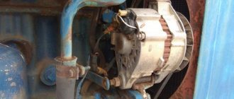
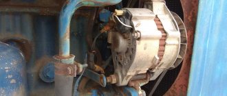
The generator on the MTZ-82 is designed to recharge the battery and maintain the functionality of lighting equipment and lighting devices. The unit is installed on the cylinder block and has a belt drive from the power plant shaft. If the equipment fails, the battery is discharged, which makes it impossible to start the engine (if an electric starter is used).
Models of generators for MTZ-82
The electrical system included several modifications of generators:
- Until the end of the second quarter of 1975, the production equipment used a G304-D1 modification unit equipped with a PP362-B relay regulator. The generator is distinguished by the location of the switching terminals on the rear of the housing.
- From the second half of 1975 (according to some sources - from the beginning of 1976), the G306 model unit began to be used, working in tandem with the PP362-B voltage regulator.
- In the 80s The G309 modification unit began to be used, characterized by increased power and increased service life of parts. Some machines used the 700-watt G464 generator, which was supplanted by the G964 product (and its modifications), which had a power of 1000 W.
- Since the beginning of the 2000s. a unit model AT 1150.04.1 was introduced (or an analogue with serial number 9695.3701-1), which has an 11% increase in output and an improved voltage corrector. On tractors with air conditioning and a D-245 diesel engine, unit 9702.3701 is used, capable of generating current up to 100 A (power is 1400 W).
The principle of operation of this device in tractor technology
To be honest, it is no different at all, except for its appearance, dimensions (dimensions), connection methods and a few more nuances.
The MTZ - 80 generator is always a three-phase device with one-sided excitation of the electromagnet, which is called G306 - D (other modifications: G - 306A, G - 304A).
For adequate operation, the G306-D generator requires direct current, which is why in the generator itself the current passes through a three-phase rectifier, turning into direct from alternating. The main parts of the G306 - D, installed on Belarusian tractors of the MTZ brand - 80, 82 and similar models, are a static device and a rotary device (stator and rotor).
The stator of this model is made of several electrical steel sheets, and a three-phase coil with winding is attached from the inside to the protrusion. The rotor is made using a similar technology and looks like a star with six corners, pressed onto the shaft, where it is attached.
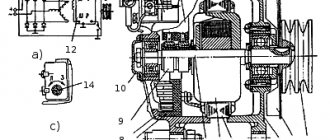
You can see a detailed diagram of the G306-D generator in the figure:
1 - Cover of the control device; 2 - Screw; 3 - Washer; 4 - Washer; 5 - Nut; 6- Washer; 7 - Washer; 8 - Nut; 9 - Washer; 10 - Washer; 11 — Insulating washer; 12 - Insulator; 13 — Rear cover; 14 - Output panel; 15 — Bolt M6x53; 16 - Rectifier; 17 — Spacer sleeve; 18 — Bolt M4x27.5; 19 — Phase insulator; 20 — Split bushing; 21 — Excitation coil; 22 — Coupling bolt; 23 - Ball bearing; 24 - Screw; 25 - Nut; 26 - Washer; 27 - Pulley (single-strand); 28 - Fan; 29 - Screw; 30 - Bearing cover; 31 - Ball bearing; 32 - Bolt; 33 — Front cover; 34 - Shield; 35 - Bolt; 36 - Washer; 37 — Rotor bushing; 38 - Nut; 39 — Washer; 40 - Washer; 41 - Bolt; 42 - Nut; 43 - Bolt; 44 — Generator bracket; 45 - Stretching; 46 - Rotor; 47 - Nut; 48 - Stator; 49 - Plank; 50 - Bolt; 51 — Thrust washer; 52 — Screw M8x28; 53 - Regulating device.
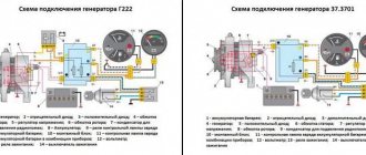
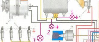
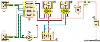
Connection diagram for the electrical circuit of the MTZ tractor - 80, 82 and its modifications:
Design and operating principle
The unit is mounted on the side of the engine crankcase on a rotating base; the upper fixation point allows you to adjust the tension of the drive belt. Torque is transmitted from a pulley mounted on the toe of the crankshaft using a segment key. The belt also rotates the pump of the liquid cooling system; if the drive breaks or the generator rotor is jammed, further operation of the tractor is impossible. The end covers of the housing have shaped channels for supplying air and draining water entering the internal cavities of the product.
An electrical machine consists of a stator, inside of which there is a fixed package of sheets stamped from electrical steel, on which there are copper windings. The coils form phases, within which the elements are closed in series, the phases themselves are combined according to a triangle diagram. A rotor shaft is mounted inside the stator on ball bearings, and a package of steel plates is pressed onto the axis. The supports are secured in removable covers. A stamped impeller is provided at the toe of the shaft to ensure cooling of the equipment.
Ball bearings are equipped with rubber protective caps that prevent water from washing away the lubricant. The design of the equipment includes excitation coils located at the ends of the stator. At the moment of operation, voltage from the battery is supplied to the windings, allowing the generator to be brought into operating mode.
The rectifier unit mounted inside the installation casing is equipped with a metal casing that provides cooling of the semiconductor diodes during operation.
If there is no battery on the tractor (the diesel engine is started using a PD-10 gasoline starter), then it is necessary to transfer the generator from the independent excitation mode to the parallel excitation state. To do this, you need to briefly (for 1 second) connect a 12 V DC source to the excitation windings. The positive cable is applied to terminal Ш, and the negative cable to terminal M. The procedure ensures the magnetization of structural parts, which allows you to put the generator into operating mode without external influence .
After the engine starts, the rotor begins to rotate, inducing a magnetic field in the stator protrusions, which varies from minimum to maximum depending on the position of the moving rotor. The created ripples make it possible to induce an alternating 3-phase current in the stator windings, which is then rectified by the semiconductor unit. The voltage level is adjusted by a separate relay, which has a season switch (in winter, the generated voltage is higher, which ensures recharging of the battery with cooled electrolyte).
Generator connection diagram
The connection diagram of the generator to the tractor's on-board network does not depend on the equipment model.
The design provides 3 or 4 outputs:
- point B or + is used to switch the positive wire from the battery;
- block M is connected to the negative pole of the battery;
- connector D (used on new versions) passes through the charging indicator device and the ignition switch to the positive output of the battery;
- plug Ш is brought out to the tractor body (negative pole);
- point W is found on part of the generators and is connected to the tachometer.
Process description
The generator is mounted on the engine, then the belt tension is adjusted, after which the upper fixing bolt is tightened. The wiring is connected to the terminals located on the rear of the unit, in accordance with the electrical diagram of the tractor. If the switching is incorrect, the generator will not work; when you turn the key in the lock, the red no-charging lamp should light up. After starting the engine, the indicator automatically turns off, indicating the correct operation of the battery charging system.
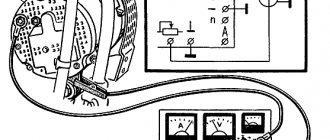
Winding check
The winding test is carried out with the motor turned off and the cables disconnected from the generator. For testing, you need a test light and a charged 12 V battery. To check the excitation coils, you should apply negative power to block M, and connect the positive plug of the battery through a lamp with connector Ш. When the coil is working, the current in the circuit drops, the lamp burns dimly.
Full heat indicates a breakdown between the windings and the generator casing, and the absence of glow indicates a coil break.
Additional tests to check the stator winding and rectifier:
- Apply a negative signal to point M, and connect the positive pole to terminal B, connecting a test lamp to the circuit. Under normal conditions, the indicator does not light; if the diodes are damaged or the positive output to the body of the electrical machine is broken down, the lamp will turn on.
- Apply negative power to any AC contact (before the rectifier), and connect the positive wire to block B through the test light. If the rectifier is working properly, the lamp will not turn on; if the diodes of straight polarity break down, it will light up.
- Connect the positive terminal to the AC connectors, and connect the negative terminal to terminal M. If the lamp is on, then it is necessary to replace the reverse polarity diodes. There is also a short circuit between the stator winding and the generator housing.
Signs of stator winding malfunction
To begin with, it would be nice to know what connections are used for this device. This is a simple matter: the negative wire of the battery is attached to the “M” terminal of the generator, and the positive wire is connected to the “W” terminal through a test lamp.
- As mentioned above, if the winding is faulty, the indicator light on the dashboard will not light up, or will light up very weakly. In addition, the current strength will not exceed 3-3.5 amperes.
- If the light does not light up at all (regardless of the modification of the tractor engine), then the winding is simply torn, rotted, or oxidized (it must be emphasized).
- We change the connection. We throw the minus terminal of the battery onto any terminal of the generator, and the plus terminal again through the indicator light to terminal B of the generator.
With this connection, the lamp will not light up, but... If it manages to turn on, it means:
- one diode or several at once has shorted;
- the insulation between the heat pipe and the rectifier is broken;
- The positive wire on the generator housing is shorted.
Recommendations
As they say, if you're not sure, don't overtake. If you cannot guarantee your knowledge of electrical engineering, then you should not undertake an inspection (much less a repair).
Under no circumstances (even for one second, in the form of a spark test) do not connect terminals “W” and “B” to the mass regulator - final failure and breakdown are possible.
Generator characteristics
The main technical parameters of the generators are given in the table.
| Parameter | G304-D1 | G309 | AT 1150.04.1 |
| Power, W | 250 | 1000 | 1150 |
| Operating voltage, V | 12 | 14 | 14 |
| Permissible load, A | 29 | 70 | 82 |
| Rotation speed at rated power, rpm | 3600 | 4500 | 3000 |
Maintenance of devices at MTZ
During operation, oil particles and dust accumulate on the generator, which should be removed with a clean rag. If dirt has accumulated in the internal cavities of the equipment, the unit must be removed for disassembly and cleaning with a rag moistened with gasoline. The formation of a layer of oxides on the terminals or destruction of the insulation of the wires of the tractor on-board network is not allowed.
When starting the engine, the control lamp should go out (on some tractors the indicator is allowed to blink in idle mode; when the frequency increases to 1400 rpm, the lamp turns off).
Do not operate equipment with a damaged pulley or fan impeller. It is recommended to periodically check and adjust the belt tension (deflection arrow 30 mm with a load of 3 kg). An over-tensioned drive will overload the rotor bearings. Due to wear of the elements, the normal clearance between the rotating unit and the stator is disrupted. Cracks or tears in the belt cause the drive to slip.
Frequent problems and their diagnosis
If after starting the engine the control indicator does not go out, then it is necessary to check the condition and tension of the belt. Then you should inspect the connection points between the wiring and the terminals for the presence of oxidation of the elements. If performance is not restored, you need to check the windings using a test lamp. Additional testing is carried out using a voltmeter at the nominal operating mode of the diesel engine. The voltage at the outputs should not fall below 12.5 V when switching an external load (for example, headlights and parking lights).
Uniform extraneous noise during equipment operation occurs due to loosening of the pulley nut or wear of the ball bearings. To check, you need to remove the belt, check the tightness of the pulley by hand and rotate the rotor. Metallic knocks or jerking indicate wear on the bearings and contact between the rotor and stator plates. With further use, irreversible damage to parts will occur.
The nut is tightened with a wrench. If the mounting hole in the pulley is broken, then a new part must be installed. The bearings are tightened using a screw puller, and the generator parts are simultaneously diagnosed.
The article describes the main defects of generators on MTZ-82; we ask readers to leave their feedback describing the breakdowns and troubleshooting methods.
Device Maintenance
Thanks to the successful design of such elements, they can operate for a long time without the need for repair work, even in difficult conditions, for example, in the presence of a large amount of dust and heat. The generator demonstrates stable operation even at high speeds, which indicates its reliability.
But even the most durable device requires care and maintenance, which will extend its service life and avoid the need to repair the MTZ 80 generator yourself. You should check the fastenings of the element, as well as the degree of tension of its belt. The deflection should not be more than 3 cm; if such indicators are exceeded, it is strongly recommended to tighten the belt.
It is necessary to regularly carry out troubleshooting of the product, which will allow timely detection of the presence of cracks, as well as other damage that could disrupt the correct operation of the unit. The electrical connections of the generator should be regularly cleaned when oxidizing, after disconnecting them from the battery.
Be sure to read: MTZ 82: valve adjustment