Release date: March 15, 2022
Reasoning from a car owner named Antoine: Now what do you like1. The driving position is high, good visibility, you don’t get so tired on long trips, the front seats are comfortable. In the back it looks more like a bench, but mostly children drive and it’s enough for them (I compare it with Subarami).2. Low front and rear overhangs.3. The engine is torquey, has enough power for the eyes, and the loading of the car does not matter. I have never engaged a downshift while off-road. And all-terrain capabilities depend on the tires; the more toothy, the further you go behind the tractor; A/T.4 is enough for me. Normal iron on the body, demolished on the road, stuck sideways into an icy snowdrift, no dents, no scratches. It took UAZ 15 minutes to pull out, you can’t dig it out, the iron is intact.5. I don’t have the habit of ironing hard plastic in the cabin and testing it for softness, so I’m happy with it; dirt and dust are washed off well.6. For a car weighing 2.7 tons and a 3.7 engine, the fuel consumption is quite moderate, I compare it with the 3.0 liter Mitsubishi Pajero and Pajero Sport, Prado 4.0 of my friends. By the way, a friend’s Trail Blazer 4.2 eats about as much as my Hippopotamus, so the amers are not such Troglotites when it comes to gasoline.7. Freedom of movement has appeared (without fanaticism, of course), and now you can visit many interesting places.8. Normal cost of spare parts, even in Exist.9. It started at -36 after two days of standing on the street, and it was not stored in a garage
Category: Articles, tips and recommendations for repairs
Vehicle characteristics: The vehicle dimensions are as follows: body length - 3424, width - 1100, height - 1949 mm. The wheelbase is 2603 mm. Ground clearance 221 mm. The car is equipped with a hybrid power unit. The 2-cylinder engine is equipped with a system that provides engine power output. There are 4 valves per cylinder. The diameter of one cylinder is 73 mm, the piston stroke is 70 mm. The engine crankshaft accelerates to 2000 rpm. Maximum torque is maintained up to 5000 rpm.
Posted by admin: at the request of Taras
Original name: . . . . . KAMAZ 6520
Laughter on topic: Sometimes I feel like it’s time to get down to business, but the thing lies so beautifully that it’s even somehow uncomfortable to touch it.
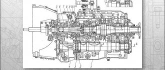
How to raise the body of a Kamaz truck is one of the most popular questions among drivers. The dump truck body is made in the form of a rising and falling platform; it is controlled not by one button, but by a system of mechanisms. To understand how to lift the body on a Kamaz dump truck, photo above, you need to know the structure of the platform, and how to control these devices, let’s start in order.
Construction of the KAMAZ 6520 platform
ATTENTION! A completely simple way to reduce fuel consumption has been found! Don't believe me? An auto mechanic with 15 years of experience also didn’t believe it until he tried it. And now he saves 35,000 rubles a year on gasoline! Read more"
The platform on the KAMAZ 6520 dump truck is all-metal, welded, has a protective visor, an opening tailgate and automatic tailgate locks, it is heated by exhaust gases to prevent the cargo from freezing in the cold season. The dump truck equipment consists of a platform, a lifting and lowering mechanism and a subframe. The volume of the Kamaz platform is 12 cubic meters, and its tilting angle is 50 degrees. The subframe is a welded structure consisting of a pair of side members, a cross-shaped reinforcement and cross members. The mechanisms for raising and lowering the KAMAZ platform consist of:
- A power take-off equipped with an oil pump is designed to take power from the gearbox;
- Gear type high pressure oil pump. It provides an oil supply of 85 l/min with a rotation speed of 1920 rpm;
- Hydraulic cylinder (one-way telescopic);
- The control unit, which serves to control the pressure of the working fluid inside the hydraulic system of the tipping mechanism, it consists of an electro-pneumatic valve and a control valve;
- The platform lift limiting valve is used to stop the platform lifting when it reaches the maximum angle;
- The oil tank is stamped in two halves; it is equipped with filters located in the filler neck and in the drain line;
- The stabilizer serves to hold the platform during unloading to avoid lateral movements
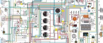
Features of electrical equipment
Now let's move on to the description of the KAMAZ electrical circuit.
All models of KAMAZ 6520, 55102 and other trucks are equipped with the following subsystems:
- Starting the power unit.
- Turning lights and hazard warning lights.
- Heating unit, power supply system, windshield cleaning mechanism.
- Vehicle interior lighting.
- Head lighting. It includes low and high beam headlights, fog lights if they are installed on the car, brake lights, and dimensions.
- Tidy. This node is considered one of the main ones in the on-board network, since it contains the main sensors, devices and instruments, including a tachometer, speedometer, fuel level sensor, etc. In addition, the control panel has light indicators that turn on when the lighting is activated , handbrake, etc. Thanks to the indicators, the driver can indirectly determine the status of some components.
- Vehicle anti-theft system, if installed.
- Fuse block. This component protects the car's electrical circuits from possible voltage surges. It contains fuses responsible for the operation of the main electrical equipment.
- A control unit, thanks to which the normal operation of the main units and equipment of the car is guaranteed.
- Audio system, if the car is equipped with one.
In order for the KAMAZ electrical circuit to operate in normal mode, the condition of the wiring must be at least satisfactory.
In addition, the operation of the electrical circuit is possible if:
- Rechargeable batteries. There are two of them in KAMAZ vehicles, they are connected to each other in series. The positive terminal of the battery is connected to the starter terminal, and the negative terminal is connected to the switch, and through it to the vehicle body. Both batteries are mounted in a special box located on the machine frame, behind the cab. Thanks to the batteries, normal operation of the ignition is ensured when the engine starts. In addition, thanks to the battery, it is possible to operate electrical equipment when the engine is turned off.
- Generator. The generator unit allows you to power electrical devices and systems while the engine is running. In addition, the battery is charged using the generator unit.
1. Diagram of hazard warning lights and turning lights
2. Scheme of car lighting and optics
3. Diagram of the stove, washer and power supply
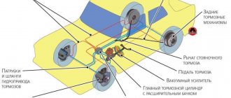
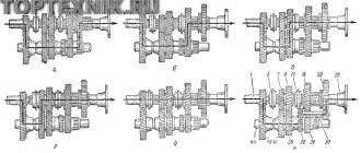
Brake drive
Modifications of KamAZ vehicles are structurally different in speed reduction mechanisms.
Brake system KamAZ 5320 diagram:
Brake system KamAZ 43118 diagram:
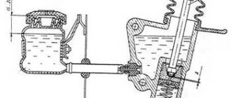
The circuit requiring the supply of air under pressure contains: a pressure increase device (9), a pressure reducer (11), a protective element (12), a cylinder (20). From the circuit, pressurized air is transported in the required dose to users. The air damping drive is divided into independent circuits, protected among themselves by means of valves. Air braking drive with five circuits: divided by double and triple regulator.
The first circuit contains: a regulator (17), a cylinder (24) with a means of measuring pressure drops (18), a pressure measuring device with two arrows (5), a lower sector of the brake valve (16), a device for opening and closing the 7th terminal (C); pressure limiting devices 8; cameras 1 (2 pieces); tractor nose wheelbase brakes, pipes.
The second circuit of the aft wheelbase contains: a regulator (17), a cylinder (22) with a valve (19) and a means for measuring pressure reduction (18), means for measuring pressure with two arrows (5), the upper part of the brake valve with two sections (16) , control bypass device (D), damping force regulator, automatic (30), cameras (26) in the amount of four pieces.
The third circuit of the reserve and stopping brake contains: a regulator (13), a cylinder (25) with a valve (19) and a pressure reduction measuring device (18), two valves (7), a control terminal (B and E). Manual brake valve (2), valve (29,32), accumulator (28), pressure reduction control device (27), valve (31,35,34), isolation valve (37), heads (38, 39), device alarm (33).
The peculiarity of the sensor (33) is integrated into the KamAZ brake system circuit so that it turns on warning lights both when using the stopping brake and when operating the main brake.
The fourth circuit does not contain a cylinder and consists of: a regulator (13), an air-powered valve (4), a chamber of a mechanical regulator of the flow area (23), a chamber for the drive of the stupor rod of the power unit (10), and a measuring instrument (14). The fourth circuit supplies air under pressure to other users: air signal, clutch force converter, etc.
The fifth emergency release circuit without a cylinder and execution elements. Consists of: regulator (17), valve (4), regulator (32).
Machines from the Kama manufacturer (53215, etc.) in the section of the pressure increasing device - pressure regulator require the installation of a moisture separator. Installation of the device - a blown beam of the unit. The same reason for installing a twenty-liter cylinder on Kama transport (5490, 5320, etc.). Location: antifreeze section - protective regulators. Dump trucks 55111, 6520 without vehicle and trailer coupling devices.
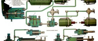
Principle of operation
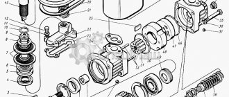
The mechanism that lifts the platform is hydraulic. It consists of a power take-off box (abbreviated PTO), an oil pump, a hydraulic distributor, a hydraulic cylinder, a valve that limits the rise of the platform, a pneumatic block, an oil tank with a filter and a whole system of hydraulic and pneumatic wires.
To turn on the hydraulic systems of the platform tilting mechanism, you need to turn on the clutch, then turn on the electromagnet “A” on the pneumatic block (look at the diagram of the mechanism components just above), which controls the power take-off. The air, in this case, enters the pneumatic cylinder 4, which turns on the PTO 3. As soon as the clutch is engaged, the oil pump starts working, from tank 1 the oil flows to the hydraulic distributor 7, from which it goes to drain.
To raise the platform, you need to turn on the electromagnet “B”, which controls the hydraulic distributor section. From the pneumatic system, air enters the pneumatic cylinder 6 on the hydraulic distributor 7 and moves its spool to the left extreme position. In this case, the drain cavity in the hydraulic distributor is closed, and the pressure cavity is connected to the line of the hydraulic cylinder 10. In the event of a dangerous increase in pressure inside the pressure line, the safety valve 11 should operate.
To stop raising the platform, it will be necessary to turn off the electromagnet “B”, which controls the hydraulic distributor section. At the same time, the cavity of the pneumatic cylinder of the hydraulic distributor will connect to the atmosphere, and the spring will return the spool to its neutral position. The hydraulic cylinder line is blocked and the platform stops in its raised state. The discharge cavity of the hydraulic cylinder is connected to the drain, and the oil coming from the operating pump is drained into the oil tank.
To lower the platform, you need to turn on the electromagnet “B”. Then air from the pneumatic system enters another cavity of the pneumatic cylinder of the hydraulic distributor and moves its spool to the right extreme position, while the hydraulic cylinder line is connected to the drain, and the platform begins to lower. As soon as the platform has finished lowering, you need to turn off the electromagnets (all without exception), and the pneumatic distributor handles must be set to its original position. And when disabling the PTO, you must disengage the clutch again.
Adjusting the lifting mechanism
Periodically check the condition and correct adjustment of the platform lift limit valve. The reliability of the valve's fastening to the subframe cross member is checked. The adjusting screw must have a lock nut and be locked. Kinking of the stem in the valve, oil leaks from under the stem seal, and leaks along the pipeline threads are not allowed. With the maximum lift angle of the KAMAZ platform correctly adjusted, its locking pins should pass freely through the drilled holes in the subframe brackets. It is not allowed to use a dump truck if the body lift angle is not adjusted.