Features of the gearbox design of the MTZ-80 tractor. Switching diagram. Useful tips.
When you are planning to purchase or have already purchased Belarusian equipment of the MTZ-80 brand, for example, or later models of the same series, you come across people who have never in their lives operated such work and/or agricultural equipment, which is nothing bad. However, many beginners have questions about its control, about changing high-speed gears, about their number, etc.
Schematic representation of the number of gears and their numerical ordinal value:
MTZ-80/82 gear shift diagram
And we’ll talk about the rest further more specifically and substantively.
General information
The MTZ-82 gear shift scheme is based on the design of the gearbox and the features of its composition. The box is a set of gears, connected in different combinations and providing different gear ratios, installed in the crankcase with a pressure mechanism. Increasing the gear ratio increases speed, decreasing it increases power.
MTZ-82 gearbox device
How to correctly change speeds on the MTZ-80?
Hello. I purchased an old MTZ-80 tractor. Please tell me how to change speeds correctly? I know the switching diagram. I’m interested in how to shift correctly when the tractor is moving; I start from a standstill in sixth gear normally without a crunch, but when I shift while moving from sixth to ninth, a terrible crunch occurs. Please tell me how to switch correctly so that this crunching does not occur?
Hello. I purchased an old MTZ-80 tractor. Please tell me how to change speeds correctly? I know the switching diagram. I’m interested in how to shift correctly when the tractor is moving; I start from a standstill in sixth gear normally without a crunch, but when I shift while moving from sixth to ninth, a terrible crunch occurs. Please tell me how to switch correctly so that this crunching does not occur?
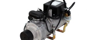
Purpose and functions of the gearbox plunger and oil seal
Among other elements, the MTZ-82 gear shift circuit contains a plunger with a switch. The blocker is equipped with a gearbox, cups and plunger disks, and relatively thin linings.
The oil seal ensures the tightness of the device and prevents oil from escaping from the housing. It is installed above the block and is driven by the transmission gear. The connection to the shaft is made through a rod. The upper part of the device contains an adapter with working bushings.
Planetary gearbox PTO MTZ-82
Crankcase and supercharger
Gear shift diagram on the MTZ-82 tractor
The MTZ-82 gear shift scheme uses an oil sump (sump) with a volume of 15 liters. It is equipped with two gears, has a durable support platform with spacers and connecting cups in the side segments. They are equipped with bushings that act as seals and prevent oil from escaping. During operation, the bushings wear out and must be periodically replaced.
The pumping mechanism consists of a set of disks, between which rigid gaskets are installed. The stands on which the device is mounted are equipped with small protrusions, and the lower support element is rigidly attached.
The injection mechanism operates in difficult conditions and requires periodic maintenance. It is necessary to regularly remove sediment present in the oil and small metal particles that appear during the friction of moving elements.
MTZ-82 gear shift procedure
The MTZ-82 gearbox has 9 forward and 2 reverse speeds. In addition, there is a reduction gearbox that doubles the number of available speeds and power levels. The gearbox stages have 2 ranges, providing different operating modes of the gearbox. Speed switching order:
Control of checkpoint Belarus MTZ-82
- Engine speed is reduced to a minimum.
- The clutch pedal is pressed all the way.
- The gearshift lever first switches on one or another stage, after which the desired gear is engaged.
- Use the gas pedal to increase engine speed while smoothly releasing the clutch.
Inexperienced drivers sometimes fail to engage the desired gear the first time. In these cases, you should turn on neutral and try again.
Shifting gears is carried out by different gearbox elements. To engage some, forks are used, others are brought into connection using a gear element. This element is a clutch with internal teeth that slides along the gear shaft in the longitudinal direction and occupies a certain position corresponding to the connection of the desired combination of gears.
The MTZ-82 gear shift pattern must be carefully studied before starting work to avoid mistakenly engaging an unnecessary gear or reverse gear.
Gearbox and PTO control Belarus MTZ-82.1
The Belarus MTZ-82.1, 80.1, 82.2 tractors with the basic configuration are equipped with a mechanical stepwise dual-range gearbox, with one range and gear shift lever located under the operator’s right hand with a mechanical reduction gearbox (18F+4R).
It is possible to install transmissions with the following configurations:
— with a manual transmission and synchronized reduction gearbox (18F+4R); — with a manual transmission and reverse gearbox (9F+9R).
Gear shifting in a transmission with a manual gearbox and a mechanical or synchronized reduction gearbox.
The controls for a manual transmission with a mechanical or synchronized reduction gear are shown in the figure.
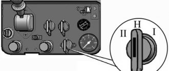
Fig. 15. Control of checkpoint Belarus MTZ-82-1, 80-1, 82-2
1 – diagram of switching stages of the reduction gearbox; 2 – reduction gear control lever; 3 – range and gear shift lever; 4 – scheme for switching ranges and gears.
Gear shifting is carried out by two levers: the transmission range and gear shift lever and the reduction gear control lever 2.
The selection of the required ranges, gears and stages of the reduction gear (the decelerating stage is the “turtle” symbol, the accelerating stage is the “hare” symbol) is made in accordance with switching patterns 4 and 1.
Switching ranges and gears is done with one lever 3, and first the range (1st or 2nd) is turned on, then the lever is moved to the “N” position, and the selected gear is engaged.
The control lever of the mechanical reduction gearbox 2 must be in the on (fixed) position during tractor operation: backward - accelerating stage ("hare"), or forward - decelerating stage ("turtle").
The control lever for synchronized reduction gearbox 2 must be in the on (fixed) position while the tractor is operating: backward - decelerating stage ("turtle"), or forward - accelerating stage ("hare").
It is possible to hold the reduction gear lever in the neutral (middle non-fixed) position to facilitate engine starting at low temperatures.
Gear shifting in a gearbox transmission with a reverse gearbox
The control elements of the Belarus MTZ-82.1, 80.1 gearbox with a reverse gearbox are shown in the figure.
Fig. 16. Gearbox control
1 – diagram of switching stages of the reverse gearbox; 2 – reverse gear control lever; 3 – range and gear shift lever; 4 – scheme for switching ranges and gears.
Gear shifting is carried out by two levers: the range and gear shift lever and the reverse gear control lever 2.
The selection of the required ranges, gears and reverse gear stages (forward stage - “forward” symbol, reverse stage – “backward” symbol) is made in accordance with switching patterns 4 and 1.
Switching ranges and gears is done with one lever 3, and first the range (1st or 2nd) is turned on, then the lever is moved to the “N” position, and the selected gear is engaged.
The reverse gear control lever 2 must be in the on (fixed) position while the tractor is operating: forward – forward gear (“forward”), or backward – reverse gear (“backward”). It is possible to hold the reverse gear lever in the neutral (middle non-fixed) position to facilitate engine starting at low temperatures.
PTO control
On Belarus MTZ-82.1, 80.1 tractors, a rear power take-off shaft is installed as standard. A side semi-independent PTO can also be installed.
Rear PTO control
Handle for switching rear PTO from independent to synchronous drive
When moving handle 11 to the extreme left position (along the path of the tractor), the synchronous drive is activated, to the extreme right - independent, to the middle - the “neutral” position.
Engaging the rear power take-off
Engaging the rear PTO Belarus MTZ-82-1, 80-1 is possible only if handle 11 is set to the “synchronous drive is on” position or to the “independent drive is on” position. In the “neutral” position, the rear PTO does not work.
The rear PTO 5 engagement lever has two positions:
— when lever 5 moves from the extreme forward position to the extreme rear position, the rear shaft is engaged;
— when lever 5 is moved from the rearmost position to the frontmost position, the rear shaft is switched off.
It is recommended to turn the rear PTO on and off while the engine is running. In the figure, lever 1 is set to the “off” position.
Fig. 17. Rear PTO connection diagram Belarus MTZ-82.1, 80.1
1 – rear PTO engagement lever; 2 – instruction plate for rear PTO control.
Switch for two-speed independent rear PTO drive
The driver of the independent PTO 2 drive has two positions:
– I – 540 min-1) – extreme, clockwise; - II - 1000-1) - extreme counterclockwise.
To set the desired rotation speed, unscrew bolt 1 by one turn, turn driver 2 to position “I” or “II” and tighten bolt 1.
Fig. 17A. Switching rotation speed (transmission bottom view)
Operation of Belarus MTZ-82.1, 80.1 tractors without using a rear PTO
When operating the tractor without using the rear PTO, the switch lever for the independent two-speed shaft drive must be set to the 540 min-1 position, the rear PTO switch handle from independent to synchronous drive must be set to the neutral position, and the rear PTO engagement lever must be set to the “off” position.
Reverse gear design
The reverse gearbox is a unit installed between the clutch and the gearbox. Performs the function of quickly changing the direction of movement back and forth without changing the gear ratio. Simply put, at the same speed you can move forward or backward, which allows you to use the “shuttle” mode.
The design of the reverse gearbox consists of two groups:
MTZ-82 gearbox design
- Mechanical transmission unit.
- Reverse gear control.
The first group consists of a set of gears that transform (change direction) the power flow. The second group ensures timely activation or deactivation of a certain operating mode, allowing you to move forward or backward. In the MTZ-82 gear shift circuit, the action of the reverse gearbox is an important and responsible function that makes it possible to instantly change motion, which is often required in difficult field conditions.
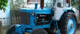
Gearbox of a Belarusian tractor
Firstly, as in any vehicle or work vehicle, the gearbox for a tractor remains perhaps the most important unit, because without it, the precise and directed movement of this machine is simply impossible - except perhaps from a hill, downhill.
The tractor's gearbox allows its driver to control the equipment, setting the required speed and traction power by switching. The MTZ-82 is equipped with an 11-speed transmission, 9 gears of which are intended for forward movement and 2 for reverse movement (reverse movement).
With the help of a reduction gearbox, the number of gears is doubled. This means that the Belarusian tractor has a total of 22 gears, 18 of which are front and 4 rear. In addition, the gearbox of the Belarus tractor operates a PTO (side power take-off shaft), which allows you to work with attachments.
For some, due to initial acquaintance and poor awareness, a logical question arises: “Why the hell are there so many gears if this unit reaches a maximum speed of only 35 km/h? Well, it’s not a racing car!” The answer is simple. The presence of a large number of gears allows you to perform labor-intensive work as accurately as possible and at the same time reduce fuel consumption by choosing the optimal mode.>
Primary shaft
The gearbox of the MTZ-82 tractor has an aggregation with the primary power take-off shaft. It is installed horizontally and is connected at one end to the clutch basket (release plate), and at the other to the secondary shaft coupling. The primary shaft is supported by two bearings. It is equipped with longitudinal teeth on which gears of 3, 4 and 5 speeds are installed. In addition, the input shaft is connected to the creeper using a gear drive.
The design of the transmission does not allow for the input shaft to operate in the neutral position. The device operates only when the synchronous or independent drive is switched on.
MTZ-82 PTO diagram
Switching circuit
The diagram shows: on a light background the inclusion of the 2nd stage of the gearbox and the corresponding gears (2,6,7,8,9 and 2nd reverse), on a dark background - the inclusion of the 1st stage and the corresponding gears (1,3, 4.5 and 1st rear). Pre-switching on the selected stage makes it possible to engage the corresponding gears.
Switching order
- The middle free position of the lever corresponds to the neutral position (indicated by the letter “H”), while the shift lever moves freely perpendicular to the axis of movement of the tractor.
- In the extreme left position of the lever, moving forward, the 2nd stage of the gearbox is turned on, when moving the lever back, in the same extreme left position, the 1st stage is turned on.
- The extreme right position makes it possible, when moving to the front, to turn on the 1st or 2nd forward speed (depending on the choice of stage). By moving the lever backwards, in the extreme right position, the 1st or 2nd rear speeds are activated according to the previously switched gear stage.
- In the middle right position: by moving forward, engage the 9th gear with the 1st gear stage engaged, by moving the lever back, in the same position, engage the 3rd or 6th gear, respectively, of the selected stage.
- The middle left position makes it possible to move forward to engage the 4th or 7th gear and by moving backward, in the same position of the lever, to engage the 5th or 8th gear in accordance with the previously selected step.
Correct gear shifting
When making a switch, you should understand that when the clutch is connected to the engine, rotation occurs in a continuous flow on the input shaft of the gearbox and for any switching you should interrupt the flow by depressing the clutch pedal, thereby stopping the movement of all parts of the gearbox. This creates conditions for synchronizing the rotation of parts for comfortable engagement of movable gears.
Before shifting, the engine speed should be reduced, then the clutch pedal is pressed all the way, the shift lever is moved to the neutral position and then from the neutral position it is switched to the selected gear mode, after which the clutch pedal is smoothly released. Switching should not be accompanied by a grinding mechanism. If it is difficult to engage gears due to wear of gearbox parts, you need to use the double clutch technique. That is, the clutch pedal is depressed when the lever is moved to the neutral position, then released and depressed a second time before engaging the selected gear. After switching on, the pedal is also released smoothly, and smoothly does not mean slowly.
The correct choice of gear ensures safety, quality work and high productivity with optimal load on all mechanisms of the tractor and the equipment used.
The gearbox of the MTZ-80, MTZ-82 tractor is a complex and expensive mechanism. The structural arrangement of this tractor unit complicates and complicates its repair. To replace one part, it is often literally necessary to disassemble the tractor floor. Repairs require enormous labor costs and qualified specialists. Therefore, when operating the tractor, it is recommended to strictly adhere to the requirements and recommendations of the manufacturer. When performing work, you must comply with speed limits in accordance with the developed technological maps, excluding overloading of gearbox mechanisms and parts.
Maintenance of the MTZ-82 gearbox
The design of the MTZ-82 gearbox has many moving and rubbing parts. Trouble-free operation of all elements is possible only if they are in proper condition, timely technical inspection, and abundant lubrication of all parts. The following malfunctions may occur from irregular maintenance:
Possible malfunctions of the MTZ-82 PTO
- Creaking noise when changing gears.
- Increased lining clearances.
- There is play in the gear shift lever, leading to incomplete or involuntary gear engagement.
- Extraneous noise, grinding or creaking in the box during operation, indicating a violation of the interaction of the elements.
A technical inspection of the gearbox should be carried out once a month. This allows you to increase the service life of the gearbox and rear axle, and ensure appropriate operating conditions for all structural elements. Regular inspection will allow you to promptly detect signs of emerging faults and take measures to eliminate them, without leading to premature major repairs.
Video on the topic: Test drive and review of the Belarus MTZ-82 tractor
Publications on the topic
We learn how to repair the K-700 tractor transmission
Features of diagnostics and repair of the KamAZ 5320 gearbox
Features of the YaMZ-236 gearbox design
Gearbox device
Sectional diagram of the MTZ 80 box
Speed switching is carried out by moving spur gears along the splines of the shafts, forming a gear ratio corresponding to a particular gear. Direct switching occurs using a shift lever connected through a control mechanism with forks that move gears and gear blocks.
Design
The design of the unit is made in the form of a two-stage, four-shaft, gear reducer, assembled in a solid cast iron crankcase, located between the rear axle housing and the reduction gear housing with clutch.
The shafts rest on bearings installed in the walls and middle partition of the gearbox housing. Some gears are made integral with the shafts, others are mounted on splines or rotate freely.
MTZ 80 gearbox diagram
- Primary shaft 1 (in the diagram) receives torque through the clutch from the tractor engine. A sliding block of two gears 3 and a gear 4 are installed on the shaft splines. Block 3 forms the gear ratio when moving it along the shaft in front to the 5th and 8th gears, moving backwards to the 4th and 7th. Another gear 4 forms, in mesh with the inner rim of gear 5 of the secondary shaft, a direct transmission corresponding to 9th speed. When this gear moves forward, 3rd and 6th gears are engaged.
- The intermediate shaft 14 participates in the formation of the gear ratio and the transmission of torque to the secondary shaft 7 of the gearbox, forming, with the gears of the primary shaft and the additional shaft 27, gear pairs of gears of the respectively engaged stage and gear. The block of driven gears (25, 24 in the diagram) is rigidly mounted on the shaft and passively interacts with the movable gears of the primary shaft 1. The freely rotating block 22 transmits rotation to the additional shaft 27. The only movable block of gears, the intermediate shaft, is the gearbox gear switching block 18, transmitting rotation to the secondary shaft. By moving the block to the front, engagement occurs with the outer rim of gear teeth 5 and the first stage of the gearbox is turned on (1st, 3rd, 4th, 5th and 1st rear). By moving the block 18 back, the block is engaged with the internal teeth of the freely rotating gear 16, and the second stage (2nd, 6th, 7th, 8th and 5th rear) is engaged in engagement with gear 8. Inside the intermediate shaft 14 there is a shaft 15 driving the main, rear PTO.
- Additional shaft 27 performs the function of forming the gear ratio of 1st and 2nd gears and two rear speeds. When moving along the splines of the gear shaft 26 in the forward direction, engagement occurs with the reverse intermediate gear 28, which rotates on a separate axis and transmits reverse rotation to the intermediate shaft. By moving the gear of the additional shaft backward, engagement occurs with the corresponding driven gear 25 of the intermediate shaft, and the 1st or 2nd forward gear is activated according to the selected gear stage.
- The secondary shaft 7 transmits rotation and the generated gear ratio to the drive gear 10 of the rear axle drive of the tractor. The shaft is made in one piece with gear 5, the internal gear ring of which is involved in the formation of direct transmission with gear 4 of the input shaft. The external teeth of this gear interact with the gear of the shift block 18 of the first stage of the gearbox. The second gear 16 is firmly mounted on the shaft and participates in the activation of the second stage.
- The slider mechanism interacts with the shift lever and ensures the transmission of movement to the forks that move the gearbox gears. The mechanism locks fix the position of the activated gear and prevent the simultaneous activation of two gears.
If necessary, a side PTO or speed reducer is installed in the left hatch of the box body instead of a cover, and a transfer case is installed in the right hatch.
The MTZ 82 gearbox is distinguished by an additionally installed transfer case to drive the front drive axle, in the right hatch of the gearbox housing in the direction of travel of the tractor. The drive is carried out from the driven gear of the secondary shaft through the intermediate gear.
Modern modifications of the MTZ 80 (82) are equipped with gearboxes with hydraulic clutches, which perform the function of activating the selected gear ratio. Switching occurs by applying oil pressure to the clutch. The clutches are controlled through the spool valve of the gearbox hydraulic distributor. Hydraulically controlled gearboxes feature smooth and comfortable shifting.
Features of gearbox operation
Correct operation of the gearbox consists of monitoring the condition and timely maintenance, as well as the correct choice of the speed mode for switching it during the work performed by the tractor.
The absence of lubricant leakage in the joints of transmission housings and hatches is monitored. The oil level is controlled through the inspection hole on the right side of the gearbox housing. When unscrewing the hole plug, the level must be no lower than the bottom edge of the hole, and the tractor must be in a horizontal, level position.
Lubricant replacement is done during scheduled maintenance 3 every 960-1000 operating hours. Often replacement is done during seasonal maintenance, changing the oil to a different brand.
The oil is drained when the transmission is warm, immediately after stopping. The drain plugs are located in the lower part of the gearbox, clutch and rear axle housings. After draining, the magnets are cleaned of metal debris that occurs during active contact of mechanism parts. Oil is refilled through the plug hole in the top cover of the box body.
Used oil brands:
- Transmission: TAp-15V, TSp-14, TE15 EFO, TM-2-18
- Motor: M12 G1
If extraneous noise, hum, or rattle appears in the box, you should stop operating the tractor and carry out technical diagnostics. checkpoint condition Timely detection of a problem and its elimination will protect equipment from more serious breakdowns.