Device
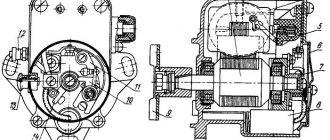
Inside the housing of the magneto of the starting motor there is a transformer to create a high voltage current and a permanent magnet - a rotor - pressed onto a shaft rotating on two bearings. A breaker cam is attached to the front end of the rotor shaft , and a driver is attached to the rear end . When installing the device on the engine, the driver fits into the groove of the magneto drive gear. The housing is closed with a cover on which the breaker contacts and the terminals of the transformer windings are mounted . The breaker is closed with an easily removable cover.
1 - body; 2 - core; 3 — transformer cheek; 4 - leash; 5 - rotor; 6 — ball bearing; 7 — breaker cam; 8 - capacitor; 9 - eccentric; 10 - fixed contact; 11 - moving contact; 12 - screw; 13 — breaker cover; 14 — output of the transformer winding; 15 — housing cover; 16 - primary winding of the transformer; 17 - secondary winding of the transformer.
The primary winding of the transformer
is connected at one end to a movable contact isolated from the housing , and at the other through the magneto housing to a fixed contact . The secondary winding is connected at one end to the primary winding and at the other end to the central electrode of the spark plug . The side electrode of the spark plug, through the engine housing, is connected to the housing of the magneto and starter.
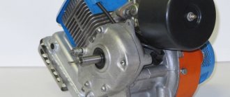
PD-10U STARTING ENGINE DEVICE
Starting motor speed regulator PD-10U
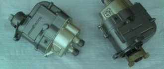
Magneto starting motor PD-10U
The magneto is used to produce the high voltage electrical current needed to produce a spark.
The PD-10U starting engine uses a single-spark magneto M-124 or M-24A1 of right rotation with a flange mount and an automatic advance clutch MC-22A, which regulates the moment of spark formation in the spark plug depending on the number of shaft revolutions.
The electric current in the magneto is created by crossing the magnetic lines of force of a rotating permanent magnet (roto-pa 10, Fig. 73) with a fixed primary winding. The current circuit in the low voltage winding 3 is closed and opened by a breaker, and a high voltage current is induced in winding 4, which is directed through the fixed contact 11 to the spark plug of cylinder 1 of the starting engine.
The breaker consists of a movable lever 9 and a cam 12. One end of the low voltage winding is connected to the iron core 5, i.e., to ground, and the other end is connected to the insulated fixed contact of the breaker.
The movable contact 15 of the breaker, pressed against the fixed contact 11 by means of a spring 13, is connected to the ground, and through the ground to the core, and therefore to the other end of the low voltage winding. A cam 12 is attached to the rotating rotor, which, when rotated, pressing on the heel of the swinging lever 9 of the breaker, disconnects the contacts of the breaker. The breaker opens the low voltage winding at the moment the highest current appears in it. Then a high voltage current is excited in winding 4.
The low voltage winding consists of approximately 155 turns of 1 mm diameter copper wire. The high voltage winding, wound on top of the low voltage winding, has 11-12 thousand turns of wire with a diameter of 0.1 mm. The wire of both windings is covered with special insulation. The voltage created in the low voltage winding is 12-20 V, in the high voltage winding - 12-20 thousand V.
The breaker contacts are made of refractory tungsten or platinum-iridium alloy. At the moment of complete divergence of the contacts, the gap between them should be within 0.25-0.35 mm. This gap is adjusted with the breaker contact bolt, which is locked with a lock nut.
To reduce sparking and burning of the breaker contacts, a capacitor 7 is connected in parallel with them, consisting of metal sheets isolated from one another, rolled into a cylinder.
To prevent damage to the winding insulation in the event of a spark plug failure, the magneto has a spark gap A, in which a spark jumps with increased resistance between the spark plug electrodes.
The ignition is turned off with button 8, which closes the low voltage winding to ground.
Rice. 73. Schematic diagram of a magneto: A - spark gap; 1 - spark spark plug; 2 - high voltage wire; 3 - low voltage winding; 4 - high voltage winding; 5 - core; 6 — core stand; 7 - capacitor; 8 — ignition switch button; 9—breaker lever; 10 — magneto rotor; 11 - fixed contact; 12 — breaker cam; 13 - spring; 14 — clutch for automatically changing the ignition timing; 15 - moving contact.
content .. 41 42 43 ..
Principle of operation
When the rotor rotates, an alternating magnetic flux , due to which an alternating low-voltage electric current .
The current in the primary winding creates an alternating magnetic flux that crosses the secondary winding of the transformer. At the moment when the current in the primary winding reaches its greatest value, the cam opens the breaker contacts. The primary winding circuit is broken and the magnetic flux disappears.
In this case, a high voltage current is induced , which is supplied to the spark plug, resulting in a spark discharge between the electrodes . To reduce the burning of the breaker contacts, when opening, a capacitor is connected in parallel with the contacts.
Visual audit and regulation
Uninterrupted operation of D-240 tractor engines and its modifications, without unscheduled repair work, is possible only with regular visual monitoring of the magneto condition and its prevention.
After 960 hours of operation of the tractor power unit, it is necessary to remove and inspect the integrity of the magneto cover, and also measure the gap of the breaker contacts. If dirt, carbon deposits or scale are found on the contacts, they must be cleaned with a special tool - a needle file, which does not leave a metal abrasive. The same procedure is recommended for long-term idle equipment.
After 1440 hours of operation of the power plant, the cams on the breaker should be examined using tissue paper for the presence of lubricant, which is necessary to prevent rapid wear. If it is not available, apply 3-4 drops of turbine oil.
The gap of the contacts of the breaker mechanism is measured using a feeler gauge intended for this purpose (a feeler gauge is sometimes placed on a special needle file), at their maximum separation, which is obtained by rotating the engine crankshaft.
When adjusting the contact gap, rotate the contact post by inserting a screwdriver into the eccentric slot, and be sure to loosen its clamp by releasing the fastening screw.
After two years, regardless of the hours of inactivity and operation of the tractor, maintenance of the bearings located on the magneto rotor is mandatory. It includes work on disassembling the magneto and removing residual lubricants from the bearings, as well as washing the separator in gasoline. A new, specially designed grease UN (OST 38.156-74) is applied to the bearings.
In case of malfunctions, bench tests of the magneto are carried out. Correctly adjusted ignition ensures long-term trouble-free engine service.
Settings
To set the ignition timing, the holes in the magneto mounting flange are made oval. As a result, the magneto housing rotates together with the breaker contacts relative to the cam connected to the engine crankshaft, and this changes the opening moment of the contacts .
- The ignition timing is set when the engine is not running. Ignition occurs 27° before TDC, which corresponds to a piston stroke of 5.8 mm below top dead center.
- The largest spark discharge between the spark plug electrodes is obtained if the gap between the breaker contacts in the open state is 0.25-0.35 mm. The gap is changed by turning the eccentric with the screw loosened.
Diagnostics of technical condition
Diagnostics is carried out by performing the following procedure:
- The first stage is connecting the high-voltage cable to the voltage terminal.
- The second end of the cable is constantly held at a distance of about 0.5-0.7 centimeters from the device body.
- Maintaining position near the wire. Next comes a sharp turn of the rotor in the direction of rotation. The spark should jump as a result of this movement; if everything is in order, the magneto is adjusted correctly. If there is no spark or is too weak, there is a high probability that the installation requires a malfunction check. If necessary, adjustments are made.
Common malfunctions and their repairs
Here are just a few of the most common problems magneto owners may encounter:
- Failures during sparking. There are several reasons for this situation and ways to resolve the problem. Possible problems include: contacts burn, oxidize; the gap adjustment is violated; the lever cushion at the breaker is worn out; The capacitor element was broken. If an element fails, it is completely replaced. When the problem is in the gaps, they undergo additional adjustment. Contacts are also changed or completely cleaned. How to set up the magneto is described further.
- Complete lack of spark. This often happens because the transformer wiring has broken, there has been a short to ground, or the insulating layer that supplies the high-voltage cable has broken through. If problems arise with the transformer, the unit must be replaced. You can eliminate the short circuit itself or change the cable when an insulation breakdown occurs.
- A broken capacitor is the most likely cause of a spark that is too weak. In this case, the part must also be replaced.
Candle and armored wire
It is recommended to abandon the caps used for armored wires. It is better to use an alligator clip.
The armored wire itself also requires additional testing. This concerns two elements:
- Fastening in the mounting socket.
- Base for a candle.
Complete stripping of the wire from each end by 2 millimeters is an excellent reason for inspection and repair. You can check using a different armor wire instead of the one installed initially. If the spark plug is faulty, it is also replaced; the part is not repaired.
Part diagram
Capacitor
It is needed so that the contacts do not burn too much. It consists of two plates and insulation, the role of which is usually played by foil. Everything is rolled into one roll and placed inside the case. In some cases, if the housing is damaged, the capacitors can be adjusted using sandpaper. It is important that the structural parts do not overheat during operation. Adjusting the magneto after this will not help.
Be sure to read: Fuel injection pump on MTZ-82
Sometimes it is recommended to install two capacitors at once, then the operation of the mechanisms will be more reliable and stable.
About breaker contacts
If they become faulty, the first recommendation is to clean the surface using a special flat abrasive plate. The work can be done without problems with a flat file with a fine notch. Cleaning with sandpaper or glass paper will not give the desired result. The contacts wear out too quickly, and in this case a flat surface cannot be obtained.
From time to time, contacts also require cleaning from plaque and adjusting the gaps between parts . The main thing is not to lose a single part during disassembly. The contact spring is subject to malfunction or straightened in the opposite direction.
Coil or transformer
It is easy to repair the tractor magneto for such parts. This same part of the engine rarely fails; it can operate uninterruptedly for a long time. If the part has become unusable, then it must be replaced with exactly the same, but working model.
Rotor
The main thing is that it does not crumble or break during operation. From time to time the rotor can become demagnetized. If the part really turns out to be damaged, then it is replaced. The main thing is not to forget to remove metal fragments, sometimes they remain inside the magneto housing. Bearings require separate inspection and lubrication.