Hydraulic valves MP80 with spool valves of types 1,2,3,4 replace P80 Hydraulic spool valve P 80 price, availability in Chelyabinsk
They are responsible for distributing and regulating the flow of hydraulic oil from the pump to hydraulic motors, power cylinders and other working parts.
They protect the hydraulic system from overload in the “Lifting” and “Forced Lowering” positions of the spool valve.
The distributor of this series belongs to monoblock and valve-spool valves.
Hydraulic distributor R-80: diagram, device, connection, do-it-yourself repair
The P-80 hydraulic distributor is used on tractors produced by MTZ and is designed to redistribute the circulating fluid of these units. The mixture flows from the pump into the working space of the cylinder. The design of the device makes it possible to adjust the oil pressure in the system and fix attachments in the required position. In fact, with the help of the unit, the working equipment of the equipment is controlled.
Buy hydraulic distributor P 80, MP 80 in Chelyabinsk
MR dump truck Power steering MRS R80 R160 MR80 MR100
| Name | Description | |
| Tipper hydraulic valves MR100.T1 | price 8400 | Order |
| Tipper hydraulic distributors MR 100.T2.P | price 6360 | Order |
| Name | Description | ||
| Power steering hydraulic distributor 50.-3406015A | price 2200 | Order |
| Name | Description | ||
| Sectional hydraulic distributor MRS 70.4/1.RM.111 (890) | price 9850 | Order | |
| Sectional hydraulic distributor MRS 70.4/2.RM.111 (1221) | price 9850 | Order | |
| Sectional hydraulic distributor MRS 63.4/1.PL.4.5 (005) | price | Order | |
| Sectional hydraulic distributor MRS 63.4/1.DV.4.6 (006) | price 18500 | Order | |
| Sectional hydraulic distributor MRS 63.4/1.PL.4.6 (028) | price 18500 | Order |
| Name | Description | ||
| Hydraulic distributor P 80-3/1-22 (211) | price | Order | |
| Hydraulic distributor P 80-3/1-22 (214) | price | Order | |
| Hydraulic distributor MP 80-3/4-222 (170) | price 6400 | Order | |
| Hydraulic distributor MP 80-4/1-222 (170) | price 6400 | Order | |
| Hydraulic distributor MP 80-4/1-222 (174) | price 6400 | Order | |
| Hydraulic distributor MP 80-4/1 444-4 (311) | price 6400 | Order | |
| Hydraulic distributor MP 80-4/1 444-4 (508) | price 6400 | Order | |
| Hydraulic distributor MP 80-4/1 444-4 (604) | price 6400 | Order | |
| Hydraulic distributor MP 80-4/4-222 (129) | price 6400 | Order | |
| Hydraulic distributor P 160-3/1-111 | price 11900 | Order | |
| Hydraulic distributor P 160-3/1-111-10 | price 11900 | Order | |
| Hydraulic distributor P 160-3/1-222 | price 11900 | Order | |
| Hydraulic distributor MP 100.3.000A left. (1 drain) | price 10900 | Order | |
| Hydraulic distributor MR 100.3.000A-01 right. (2 plums) | price 10900 | Order |
A larger number of distributors are equipped with spool valves of types “2” and “4”.
Spool type “2”.
- Automatic shutdown from positions: raising, lowering, fixing.
- 4 switching positions: lift, neutral, lower, floating (used when attaching an attachment or towed device).
Spool type "4".
- Switching positions: lift, neutral, lower.
- There are no fixed positions and no automatic shutdown, which is used on loading and unloading units (tractors, bulldozers, loaders, etc.)
Spool valves
Spool valves are cylinder-shaped rollers that are carefully processed. There are provided machined sockets in specific locations. They are placed in suitable and prepared places in the body. During installation, the spools pass through special channels and cavities towards the axes. As a result, the spool elements slightly open some channels, closing other working holes. This design helps change the direction of fluid flow. The spools are driven by a lever that operates in four positions:
The indicated positions of the P-80 hydraulic distributor have a certain fixation. Holding the lever by hand is only possible in the “forced lowering” position. The spool devices are equipped with an automatic return system to the neutral position from fixed modes.
Division by spool type
Examples of designations: P 80-3/x -ХХХ or P 160-3/x -ХХХ
| Spool type | 1 | 2 | 3 | 4 |
| Example notation | 1, 11 or 111 | 2, 22 or 222 | 3, 33 or 333 | 4, 44 or 444 |
| Spool positions | "Rise", "Lower", "Neutral", "Float" | "Rise", "Lower", "Neutral", "Float" | "Rise", "Lower", "Neutral", "Float" | "Rise", "Lower", "Neutral" |
| moving the handle to the “Lifting” position | press and hold, no fixation | handle translation, fixation | handle translation, fixation | press and hold, no fixation |
| returning the handle from “Lift” to “Neutral” | remove your hand from the handle | automatically (on reaching the set pressure) | automatically (on reaching the set pressure) | remove your hand from the handle |
| moving the handle to the “Lowering” position | press and hold, no fixation | handle translation, fixation | press and hold, no fixation | press and hold, no fixation |
| returning the handle from “Lowering” to “Neutral” | remove your hand from the handle | automatically (on reaching the set pressure) | remove your hand from the handle | remove your hand from the handle |
| moving the handle to the “Floating” position | handle translation, fixation | handle translation, fixation | handle translation, fixation | — |
| return from "Floating" to "Neutral" | handle translation, fixation | handle translation, fixation | handle translation, fixation | — |
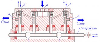
Operating principle
The design of the P-80 hydraulic valve allows the spools in the neutral position to remain under the force of the springs. They block the discharge compartment from the working grooves, thus preventing liquid from reaching the cylinders. In addition, the oil path to the drain holes is cut off. In this situation, the piston remains in a strictly fixed position. After the oil begins to flow through the pump into the discharge cavity, the lower part of the bypass valve is affected. Under this directed force, the element opens, the oil fluid is transported to the lower part of the P-80 hydraulic distributor and flows to the drain channels.
The control groove remains slightly open, while part of the oil is drained without interfering with the opening of the bypass valve. If the spool is in a floating position, both compartments communicate with each other via a drain line. The working fluid from the pump flows freely through the distributor and enters the reservoir through channels that are activated in the neutral position. In this mode, the piston is able to move under the influence of the rod load, due to the aggregation of both cylinders.
Peculiarities
The P-80 hydraulic distributor, the diagram of which is shown below, working for lifting or forced lowering, communicates one working cavity with the drain system, and the second analogue with the discharge element. The control channel is blocked by the spool belt, the oil pressure in both parts of the bypass valve piston is equalized. In this case, the valve of the redistributing mechanism goes down under the influence of its own spring. The flow of oil to the drain is completed.
Under the influence of liquid, the piston in the cylinder moves, bringing the equipment and working elements of the equipment into operation. The automatic return of the spool valves from the “lift” mode is due to the pressure created. Its value is identical to the same indicator observed when the safety valve is activated. It connects to the drain line, after which the pressure parameters drop slightly. In the opposite channel it remains consistently high, since the bypass valve is in the closed position.
Due to the pressure difference in the channels of the unit, an opening of the hole is observed, after which the oil fluid begins to flow under the booster. The spool is no longer fixed, returning under the action of a spring to neutral mode. In the forced lowering position, the working channel is connected to the waste compartment. The pressure at which the spool stops fixing is only 2 MPa.
Recommendations for the operation of the hydraulic distributor R-80 3/2-222
The hydraulic distributor R-80 3/2-222 is mounted on special equipment at the level of the top point of the oil tank. First remove the rubber or plastic plugs that temporarily closed the connecting holes in the housing.
After installing the hydraulic distributor and before putting the equipment into operation, the hydraulic system is warmed up (in the case of low ambient temperatures). It is also recommended to install filters on the tank neck and in the hydraulic system drain line. This will avoid contamination and premature failure of the hydraulic distributor. Dirty oil very quickly disrupts the operation of valves and automatic spool return devices.
Before putting the special equipment into operation, make sure that the spool is in the “Floating” position. Leaving it in the Neutral position may damage the hydraulic cylinder. This item is only intended for use when the attachment is not in use. It is also impossible to forcibly hold the spool in the “Lift” and “Forced Lowering” positions. This can lead to overheating of the entire hydraulic system.
Connection
The connection of the P-80 hydraulic distributor to pipelines or hoses is carried out exclusively through fittings, flanges and other intermediate elements. The working fluid in the system must have a purity of at least category 16 according to GOST 17216. Oil purification is carried out using a fine filter (25 microns).
It is advisable to install spool controllers that are not involved in servicing tractor equipment in the neutral position. During equipment maintenance and routine inspection, it is recommended to adjust the pressure of the safety valve to the values specified in the machine's operating manual. The data is checked using a pressure gauge connected to the pressure part of the distributor. The adjustment is performed at maximum crankshaft speed, taking into account the calculated pressure value.
The outlet pressure should not exceed 0.5 MPa, and the level of the distributor should not be lower than that of the top point of the oil reservoir. The devices in question with any type of spool valve are used in the hydraulic systems of tractors and agricultural machinery.
Technical characteristics of hydraulic distributor R-80 3/2-222
- Design - monoblock, valve-spool
- Hydraulic valve - indirect action safety and overflow
- Number of spools - 3
- Control - manual spool
- Conditional diameter - mm 16
- Working fluid flow, l/min nominal 80
- maximum 120
- minimum 20
- without hydraulic locks at Pst=7.0 MPa 150
Repair of hydraulic distributor R-80
Repairing the part in question requires certain knowledge in the field of hydraulics. Otherwise, an ineptly carried out restoration process can only make the situation worse.
Having studied the design of one hydraulic distributor of the system, you can easily understand similar drives of similar designs. They all have an almost identical structure with a similar operating principle, including modifications with multiple levers or controlled by a joystick. When diagnosing and repairing, special attention is paid to the spool, valves and housing.
Frequent malfunctions
A rather serious problem with the distributor is wear in the seats between the housing and the spool. Such a defect can be detected by touch. Its appearance is indicated by longitudinal scratches and scuffs, and vibration of the spool. It is worth noting that the spool elements are not interchangeable. Some craftsmen, when repairing the P-80 hydraulic distributor with their own hands, adjust the size of the spool from another distributor. This makes it possible to extend the service life of the part. Experts do not recommend this approach, despite the fact that professional restoration of landing gaps is a very labor-intensive and expensive process.
The main reasons for the unauthorized lowering of working equipment (bucket or boom) are lack of tightness in the rubber seals or clogging (wear) of the valve needle. If such a problem occurs, diagnosis should begin with the valve.
Division by operational purpose
| Code | Operational purpose |
| 1 | autonomous use in hydraulic systems |
| 2 | use with hydraulic valve code 3 |
| 3 | use with hydraulic valve code 2 |
| 4 | use with tillage depth regulator |
Marking options:
Р80-3/1-222, Р80-3/2-222, Р80-3/3-222, Р80-3/4-222
We offer hydraulic valves at a price and with a manufacturer's warranty.
The selection is FREE!
Hydraulic distributor P80-3/1-222
Our company is a distributor of the plant JSC “Gidrosila”
HYDRAULIC DISTRIBUTOR Р80-3/1-222 (Р80-3/1-222Г) TU 3. У 00235814-002-93
PURPOSE
The hydraulic distributor Р80-3/1-222 (Р80-3/1-222Г) is intended for installation in hydraulic systems of tractors, agricultural and road machines, where it performs the following functions: distribution of the flow of working fluid pumped by a hydraulic pump between consumers (hydraulic power cylinders, hydraulic motors and etc.); protection against hydraulic system overloads in the “Lifting” and “Forced Lowering” spool positions (safety valve mode); unloading the hydraulic system when the spool is in the neutral position by pouring the working fluid into the tank (idling); communication between the working cavities of the hydraulic cylinder and the drain (floating position). The hydraulic distributor Р80-3/1-222 (Р80-3/1-222Г) is a basic model, on the basis of which modifications are made for excavators, loaders, road machines and industrial tractors.
MP80 hydraulic valves with spools 1, 2, 3, 4 types
They are analogues of P 80 in functionality and overall and connection dimensions.
Modernized MR... models distribute and regulate pressure in hydraulic systems of machines with pumps with a capacity of 20...120 l/min.
They have superior performance parameters compared to P80. What changed?
- body with spilled internal cavities of increased cross-section without dead-end transitions;
- equipping with a different valve system that increased the range of basic characteristics;
- application of chrome coating Khtv.15 on the R80-3-024 spool increased the internal tightness performance and made it easier to control the spools.
The new phosphated body and aluminum covers without paint and varnish, galvanized surfaces of external parts have updated the design of the product, made it easier to identify products in this series and, as a result, more reliably protected against counterfeiting.
Structural updates increased the resource of the MP80 unit by 20% in relation to the P80 up to 300,000 cycles and increased the reliability of the hydraulic system in general.
MP80 is used for equipment, with the exception of options with side outlets of the distributor to the executive bodies.
Interchangeability table for hydraulic valves type MP80 | ||||
| № | Modification | Factory delivery option | Modification | Factory delivery option |
| 1 | MP80-4/1-222 | 170N | Р80-3/1-222 | 170 |
| 2 | MP80-4/1-222 | 174N | Р80-3/1-222 | 174 |
| 3 | MP80-4/1-444-4 | 311N | Р80-3/1-444 | 311 |
| 4 | MP80-4/2-444-4 | 508N | Р80-3/2-444 | 508 |
| 5 | MP80-4/3-444-4 | 604N | Р80-3/3-444 | 604 |
| 6 | MP80-4/4-222 | 129N | Р80-3/4-222 | 129 |
| Options | Hydraulic valve parameter value | |
| Р80-3/1-222 | MP80-4/1-222 | |
| Working fluid flow, l/min nominal MAX MIN | 80 100 20 | 100 140 10 |
| Inlet pressure, MPa nominal MAX MIN | 16 20 5 | 20 25 5 |
| Safety valve setting pressure, P set MPa | 20-2 | 20-2 |
| Unloading pressure at nominal flow, MPa, no more | 0,5 | 0,3 |
| Internal tightness (max internal leakage, cm³) for spool pairs at Рstat.=11.2 MPa in 30 minutes | 150 | 64 |
| Efficiency (in the “lift” position), % of nominal flow | 0,95 | 0,97 |
| Control force on the lever 400 mm, kg no more | 7 | 3 |