The 2nd generation Hyundai Solaris model, popular in the CIS, was produced in 2022, 2022, 2022, 2022, 2022, and 2023. Mostly the car is supplied to the market with 1.4 and 1.6 liter petrol engines in a liftback or sedan body. The main fuse and relay block of the Hyundai Solaris 2 remains unchanged, regardless of modification or assembly. Next, the location of the main and auxiliary fuse links is considered. The fuses for the cigarette lighter and radio are separate. The description is made in a table with explanations from the photo.
Fuses and relays in the cabin
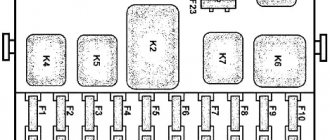
On the second Solaris, one mounting block is installed inside. The fuse panel is located to the left of the steering wheel and is covered with a plastic shield. Here are the main inserts that protect lightly loaded networks that are not directly responsible for the operation of the power plant and its equipment.
| № | Decoding |
| 1 | Voltage distribution to the dashboard junction box. The fuse is responsible for the feet. |
| 2 | Applicable only if you have an electronic key. In the classic version, reserve. |
| 3 | Spare fuse. |
| 4 | Emergency call module for rescue services. |
| 5 | Seat belt sensors, interior lighting. |
| 6 | Rear fog lights relay is installed optionally. |
| 7 | Air conditioner fuse. Responsible for buttons and operation indication. |
| 8/9 | Socket/cigarette lighter fuses for front/rear. |
| 10 | Relay for auxiliary socket and cigarette lighter in the rear of the car. The exterior mirror drives, multimedia and navigation are also powered here. |
| 11 | Installed optionally, it is responsible for the servo drive for opening the sunroof. |
| 12 | Standard immobilizer. |
| 13 | Backup fuse. |
| 14 | Distributor relay in the engine compartment and redirection of voltage to the steering column switch. |
| 15 | Rear fog light relay on the left side of the body. |
| 16 | DRL module. |
| 17 | Seat heater control unit, window switches. |
| 18 | Windshield washer fuse. |
| 19 | Interior lighting and instrument lighting in the version with automatic on/off system. |
| 20 | Trunk light, overhead interior lamp, navigation lights. |
| 21 | The main module of the acoustic installation is the power supply for the radio. |
| 22 | Power supply to the central locking relay. |
| 23 | Electronic stop switch, smart key control module. |
| 24 | Left side rear view mirror control and air conditioning module. |
| 25 | Power supply for SLM and VSM units. |
| 26 | Interior air conditioning fan fuse. |
| 27 | Gearbox lever position indicator lamp. If the slide is not locked and information is not displayed on the display, this is the fuse you need to look at. On the mechanics, he is responsible for the block in the engine compartment and turning off the stops. |
| 28 | Power supply for the right headlight/taillights, main relay for the navigation system, instrument switches and selector lever position indication. |
| 29 | Central block of ABS and ESP. There are no sensors involved here. |
| 30 | The BCM switch is on the left side of the dashboard. |
| 31 | Steering wheel heating system. |
| 32 | Front seat heating fuse. Voltage outlet to the tenna control unit. |
| 33 | Driver's door window regulator. Servo and switch. |
| 34 | Rear seat heater fuse. |
| 35 | Rear left side exterior lighting and license plate light. |
| 36 | Reserve. |
| 37 | Power supply for auxiliary equipment - air conditioning, steering wheel heater relay, seat heating switches, acoustic and multimedia installations. |
| 38 | The BCM module and the voltage output to the sound indicator of the seat belt not fastened and the backlight. |
| 39 | Airbag control head unit. |
| 40 | Front passenger window control panel. |
| 41 | General control panel for power windows on the central part of the dashboard. |
| 42 | On automatic: power supply to the gearbox mode switch. On the mechanics: distribution block under the hood, control of the keyless entry module. |
| 43 | Immobilizer, power supply for sensors and shock sensors. |
| 44/45 | Power supply for instrument cluster. |
| 46 | Electric power steering control module. |
Note! When installing a modified or more efficient audio/multimedia system, drivers often abandon the standard fuses due to their insufficient power. If there is such a design, the fuse link should be looked for in the power supply line of the device.
Replacing the mechanism of a damaged device
It is necessary to purchase a new seat for the plug of our cigarette lighter, which costs about $10. To dismantle a spare part that has become unusable, you must first open the cover of the 12V socket.
Using two fingers, the index and middle of either working hand, remove the panel by inserting your fingers into these two holes. The lid will give in easily with a little applied force and move outward. We make a replacement by first removing the terminals from the socket plug, disconnecting the burnt-out part, and installing a new one in its place.
We connect the connectors at the end of the wires back and, lightly pressing the socket, fix it in its original position. The renovation is complete.
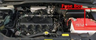
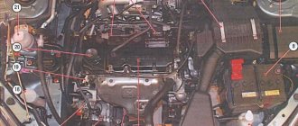
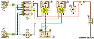
Mounting blocks under the hood
All vehicle configurations are equipped with 2 engine compartment fuses and relays. They are divided into main and auxiliary.
Main unit next to the battery
The fuse panel is located next to the battery. The most loaded inserts, responsible for groups or energy-intensive circuits, are installed here.
| Marking | Description |
| MDPS-1 | The EUR module is the main power line. |
| ALT | Distributor near the power plant. Fuse links 3-6. |
| RR DEFOG | Power circuits for heating the rear windshield. |
| ABS1/2 | Supply voltage to the ABS and ESP units. |
| BLOWER | Voltage distributor under the hood. Power supply for the cooling system head fan relay. |
| WIPER | Wiper drive, steering column switches, relay 6 in the engine compartment. |
| ENG S2 | Lambda probe 1 and 2, solenoid valve for the adsorber and intake system. |
| ENG S1 | Power supply to the engine oil supply valve. |
| ENG E2 | Supply voltage to the engine control unit and automatic transmission. |
| H/LP RH/ LH | Right and left headlights. |
| ING COIL | Voltage capacitor on ignition coils. |
| INJECTOR | Power plant and automatic transmission control unit. Supply voltage to injectors. |
| B/UP LP | Reverse light switches. |
| BATT 1/2 | Dashboard distributor, fuses 15-23/32-34 respectively. |
| IG2 | Ignition system relay No. 1. |
| C/FAN | Power supply for the engine cooling system fan. |
| ENG E1 | Main and relay 13 in the engine compartment. |
| B/ALARM | Alarm sound indicator. |
| ENG T | PCM module and ECU secondary circuits. |
| LO/H LP | Low beam head optics. |
| HI/H LP | Likewise for the long-distance lighting mode. |
| F/PUMP | Power supply for the fuel pump. |
| HORN | The sound signal is the main one. |
| ENG E3 | ECM/PCM – secondary circuits of electrical circuits of elements. |
| A/CON | Electromagnetic clutch of the air conditioner. |
| BATT 3 | Power supply to fuses 1, 5, 6 and size relays under the dashboard. |
| IG1 | Ignition system switch. Supply voltage to the lock cylinder. |
| P/OUTLET1 | The power part of the auxiliary circuit is the fuses for the cigarette lighter and socket. |
Secondary block
The auxiliary area is designed to ensure the functionality of the heating elements of the windshield anti-icing system. The device is mounted on the starboard side in a plastic case with a hinged lid. The description of the elements is as follows:
| Name | What is he responsible for? |
| FR HTD LH/RH | Power supply for the power parts of the front window heating elements on the left/right side, respectively. |
| FR HTD | Regulator and tenn control buttons on the dashboard. |
| RLY | Power relay for turning on the front window heater. |
Repairing the wiring supplying the cigarette lighter
In order to carry out this procedure, you need to go to a service station or find a suitable electrician. You won't be able to deal with this on your own. The only nuance that you can solve yourself is to check the presence of power at the terminals and open connections available for testing. You will need some equipment:
- tester;
- voltmeter;
- multimeter
Having even a little knowledge in the field of physics or electrical engineering at the school level, you can conduct a superficial diagnosis of the electrical component of the system. If all the wiring turns out to be in perfect order, then the third and only problem needs to be solved.
Why do you need heated seats?
Having a similar function in a car is very necessary during periods of severe frost. Getting into a car that has been parked for a long time in the cold is unpleasant and unsafe for the health of the driver and passengers.
Overheating of seats also poses a danger to human health and to the car.
There are many articles on the Internet about the benefits and harms of heating. Let's dot all the i's. Driving for a long time with the heater on can have a bad effect on ladies and guys. Accordingly, it is recommended to use this option consciously in order to protect yourself from cystitis or prostatitis.
General rules for using heating:
- Do not allow the seats to become significantly overheated.
- When it's cool, turn on the heating and don't sit on them for a while.
- Once the seats have been warmed up, turn off the system. Next, heat the interior with a stove.
- You cannot stay in the salon in warm clothes for a long time.
Following these rules will help you protect yourself from overheating and not harm yourself.
Replacement
seat heating fuse
It was difficult to figure out where he was.
Layout diagram
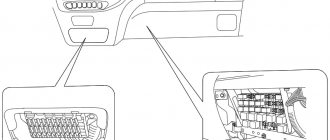
The Hyundai Solaris has two fuse blocks. One of them is located directly in the cabin. There are those fuses that can quickly lose their functionality. Accordingly, in the event of a breakdown, you will not need to climb under the hood of the car. To gain access to the block, simply remove the decorative trim using a screwdriver.
The second block is located directly under the hood. It is located on the right side of it. The block is protected by a plastic cover, which can also be removed using a screwdriver. Like any other element, it can become unusable, so it is important to know the location of each of the fuses.
The diagnostic connector is located inside the car. You can find it right in the instrument panel, next to the fuse box. To correctly select and replace fuses, you can rely on special diagrams. The original diagram can always be found on the lid. If it was replaced, you will have to use a schematic representation of the arrangement of elements proposed below.
Heated seats on Hyundai Solaris
heating element and internals.
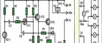
Protection
The system is protected from short circuit and overload by two fuses. One protects the control circuit, the second the power circuit. The power circuit fuse is located in the mounting block and is marked F33, its rating is 15 A.
Articles
In the event that we have neither the time nor the desire to bother with replacing the heating elements ourselves, we can always set aside about five thousand rubles and contact the service.
At the same time, it’s still worth buying heating elements for the seats yourself, it will be cheaper. The seat cushion heating element has catalog number 88199-4L070, the back heater is sold under the number 88399-4L070, and they cost around 4.5 thousand rubles.
Subtleties of preparation for work
To set up an effective system, you need to start by selecting a suitable kit, taking into account the design features of the cabin.
Popular embedded systems options:
- Installation kits from German manufacturers are the most expensive, but also the most reliable and productive. Almost every complex is equipped with overheating protection. Weaco kits also provide different operating modes.
- The Russian-made Emelya kit is slightly cheaper, but also has decent characteristics. The heating element here is made of carbon fiber or in the form of reinforced cable.
- Chinese versions are the most affordable, but you should not connect them due to their low reliability. Uneven heating, problems with the power button, and possible short circuits are common, which is typical for Autoline versions.
When choosing the appropriate option, you can also consider products from Taiwan – the Megalight kit. But for VAZ cars it is better to choose the Emelya system. To properly equip seat heating with your own hands, you need to select tools and materials.
What you will need for work:
- screwdrivers and wrenches for removing seats;
- clamps (if necessary), marker;
- scissors, knife, pliers;
- soldering iron, electrical tape, multimeter;
- If the purchased kit does not contain double-sided tape, you need to buy it separately or use glue 88.
Important:
Before you start installing the system, you should check the package contents. Sometimes you need to additionally purchase wires, a fuse connector, and adhesive.
FAQ
Using our adapter you connect to the interior lamp. Consequently, power will be supplied and disconnected to the DVR or other device, just like to the lamp. All cars implement this differently. For some it is related to the ignition, for some it is related to the central locking. In some cars, power is constantly supplied to the lamp. But you can check how it will work on your car. To do this, turn on the courtesy light to the constant lighting position and watch its behavior when you turn on the ignition and close/open the car.
Connecting to a lampshade, of course, is not the official way to connect a DVR. Everything you do with your car is done at your own peril and risk. And, theoretically, the official dealer can use the fact of connection to deny you warranty electrical repairs. But a huge advantage of connecting with our adapter compared to other methods (twisting, soldering) is that you can very easily dismantle everything and return it to its original state before going to the OD.
We do not claim that connecting to a lampshade is the most correct and safe way to connect. We are only trying to help those who have chosen this method for themselves to do it easier, faster and perhaps somewhat more correctly, without twisting the solder, etc. In any case, everything you do with your car is done at your own peril and risk. Thousands of people use this method of connecting DVRs, radar detectors and other devices. Practice shows that this is a fairly safe and simple way to connect. But you still need to be careful. We do not recommend connecting more than one consumer in this way. This can cause an increase in load and melting of the vehicle's standard wiring.
You can place an order and pay for it in our online store. Payment is made by card using the Tinkoff payment system. We ship orders within three business days from payment. Delivery throughout Russia and the CIS countries is carried out by Russian Post using first class mail. Shipping costs are calculated automatically when placing an order. After sending your order, a letter with a tracking number will be sent to your email address (Letters sometimes end up in Spam).