If it is necessary to connect additional headlights or remove the load from the main light sources, then a relay is used. The easiest way is to install a four-pin version, as it can be purchased at any car dealership, it is cheap and easy to install. The main thing is to understand the operating features and connect the wires correctly to ensure normal operation of the equipment.
First you need to prepare everything you need. Usually the same set is used:
- New headlights with brackets so that they can be installed on the car once connected and securely fixed.
- Relay for connecting light. The easiest way is to use the standard four-pin version with connectors numbered 85, 86, 87 and 30. These are sold in car dealerships and are used for both fog lights and any other light sources.
The fuse can also be placed in a standard fuse box; there is usually free space there. But this will complicate the work, since the wiring on the unit will have to be pulled separately.
Expert opinion
It-Technology, Electrical power and electronics specialist
Ask questions to the “Specialist for modernization of energy generation systems”
How to connect an ammeter on an MTZ tractor Before disconnecting the wires, make the appropriate marks on the block so as not to confuse with further connections; the blue wire refers to the high beam;. Ask, I'm in touch!
Wiring diagram of the MTZ 82 tractor in color - MTZ-80.RU
The electrical equipment of the tractor consists of sources and consumers of electrical energy, which are intended for starting the diesel engine, lighting, sound and light signaling when performing transport and other work, powering instrumentation, ventilation and heating of the cab, cleaning cab windows and other purposes where required use of electricity.
The tractor uses direct current electrical equipment with a rated voltage of 12 V. The electrical system is made according to a single-wire circuit for connecting consumers with sources of electrical energy, in which the metal parts of the tractor are used as one of the current wires. These parts are called the tractor mass, to which the negative terminals of electrical energy sources are connected.
Sources of electrical energy are a generator and a battery connected in parallel to each other. The voltage within specified limits is regulated by a relay regulator.
The battery serves as a source of electricity for all systems and electrical equipment when the diesel engine is not running, and primarily the diesel starting system, which creates the greatest load on the battery.
During this period of operation, the battery is discharged. When the diesel engine is running, when the voltage of the generators is greater than the emf. battery, all consumers are powered by the generator, including charging the battery.
Figures 77 and 78 show schematic diagrams of the electrical equipment of the MTZ-80, MTZ-82 and MTZ-80 L, MTZ-82L tractors.
Rice. 77. Electrical diagram of tractors MTZ-80 and MTZ-82:
1 and 56 — headlights; 2 and 57 — front direction indicator; 3, 27, 28, 38 and 58 - connecting panels, 4 - relay regulator; 5 - generator; 6 and 32 - plug connector; 7 - switch for the electric motor of the fan of the heating unit - cabin cooling; 8 — electric motor of the heating-cooling unit fan; 9, 15 and 17 - fuse block; 10 - coupling; 11 — lamp switch; 12 — lampshade; 13 — windshield wiper; 14 — windshield wiper switch; 16 and 21 — instrument lighting lamp; 18 — control element of the electric torch heater; 19 — control lamp of the “ground” switch; 20 — additional resistance; 22 — switch for electric torch heater and starter; 23 — high beam indicator lamp; 24 — windshield washer; 25 and 42 - rear lights; 26 and 41 — rear lights; 29 — brake light switch; 30 — rear headlight switch; 31 — central light switch; 33 — trailer socket; 34 — license plate light; 35 — push-button windshield washer switch; 36 — turn signal switch; 37 — turn signal indicator lamp; 39 — portable lamp; 40 — portable lamp socket; 43 — ground switch; 44 - battery; 45 — direction indicator switch; 46 — push-button switch for onion signal; 47 — headlight light switch; 48 - ammeter; 49 — water temperature indicator; 50 - diesel start blocking switch; 51 - starter; 52 — starter relay; 53 - blocking relay; 54 — electric torch heater; 55 — water temperature indicator sensor; 59 — sound signal; 60 — fuel level indicator; 61 — fuel level indicator sensor.
Rice. 78. Electrical diagram of tractors MTZ-80L and MTZ-82L:
1 and 55 — headlights; 2 and 56 - front turn signal; 3 - relay regulator; 4. 28. 29. 36 and 54 - connecting panels; 5 - generator; 6 and 31 - plug connector; 7-switch of the electric motor of the fan of the heating unit - cabin cooling; 8 - electric motor of the heating-cooling unit fan: 9 - coupling; 10 — lamp switch, 11 — lamp lamp; 12, 15. 17 - fuse block; 13 — windshield wiper switch; 14 — windshield wiper; 16 and 21 — instrument lighting lamp; 18 — control lamp of the “ground” switch, 19 — water temperature indicator; 20 — starter switch; 22 — high beam indicator lamp; 23 — windshield washer; 24 - central light switch; 25 — brake light switch; 26 and 39 — rear lights; 27 and 38 — rear light; 30 — rear headlight switch; 32 — trailer socket; 33 — license plate light; 34 — windshield washer switch; 35 — turn signal indicator lamp; 37 - portable lamp; 40 — ground switch; 41 — portable lamp socket; 42- battery; 43 — starting engine start blocking switch; 44 — direction indicator switch; 45 — push-button switch for sound signal; 46 — turn signal switch; 47 — magneto push-button switch; 48 — headlight light switch; 49 - ammeter; 50 - starter; 51 - magneto; 52 — spark plug; 53 — water temperature indicator sensor; 57 — sound signal; 58 — fuel level indicator; 59 — fuel level indicator sensor.
D-260 engine maintenance
Engine start blocking MTZ-1221 Belarus
Fig. 14. Scheme for blocking the start of the D-260 diesel engine
1 - starter; 2 - generator; 3 - blocking relay; 4 — starter switch; 5 — starter relay; 6 — balls of the locking mechanism; 7 - finger; 7a - retainer; 8 — lock switch; 9 — adjusting washers; 10 — range switching leads.
To exclude the possibility of starting the engine when the range is on, a special blocking device is installed on the tractor (Fig. 14). The locking device consists of a switch (8) installed in the gearbox housing on the left side, balls (6) and pins (7, 7a).
When the range is turned on, the locking mechanism opens the switch contacts and breaks the circuit of the intermediate starter lock relay (1). To adjust the opening of the switch, washers (9) are provided.
Before starting the engine, set the gearshift lever to the neutral position.
Oil level in the MTZ-1221 Belarus engine
— Check the oil level by placing the tractor on a level surface and no earlier than 3-5 minutes after stopping the engine, when the oil has completely drained into the crankcase:
— Remove the oil gauge from the right side of the engine, wipe it clean and reinstall it until it stops;
— Take out the oil gauge and determine the oil level. It should be between the upper and lower oil gauge marks.
— If necessary, add oil through the filler neck by removing the cap.
Coolant level in diesel engine D-260
— The engine cooling system operates under pressure, which is maintained by a valve in the radiator cap.
- Allow the engine to cool, place a thick cloth over the plug and slowly open the plug to relieve pressure in the system before removing the plug completely.
— Using the blade of a screwdriver inserted into the recess of the hatch cover at the top front of the hood, tilt the cover back to gain access to the radiator cap.
- Remove the plug, taking the above precautions, and check the coolant level, which should be up to the top of the filler neck.
— Do not allow the level to drop below 40 mm from the upper end of the filler neck.
Draining sediment from the coarse fuel filter and from fuel tanks
— Open the fuel tank drain plugs and the filter housing drain plug.
— Drain the sediment and water until clean fuel appears from under the plugs.
— Drain the sludge into a special container and dispose of it properly.
— Close the drain plugs of the fuel tanks and filter.
Checking the tension of the generator drive belt
— The tension of the MTZ-1221 Belarus generator belt is considered normal if its deflection on the branch between the crankshaft and generator pulleys is within 30-33 mm when pressed with a force of 40 N.
— To adjust the belt tension, loosen the generator mount and rotate the generator housing to ensure the required tension.
— Tighten the bolt securing the bar and the nuts of the generator mounting bolts.
Checking the diesel air cleaner
Check the condition of the paper filter elements (PFE) for paper breaks and whether the PFE is installed correctly.
To check the main filter element (PFE), perform the following operations:
— unscrew the wing nut and remove the pan; — unscrew the wing nut and remove the OFE; — check for contamination of the control filter element without removing it from the housing.
It is not recommended to remove the control filter element from the housing. Contamination of the control filter element indicates damage to the BFE (break of the paper curtain, peeling of the bottoms). In this case, wash the EFE and replace the OFE.
Cleaning centrifugal oil filters of the D-260 engine and gearbox
Wiring diagram MTZ 82(80) with large and small cabin with description
Belarus tractors are equipped with single-wire electrical equipment designed to start the engine, operate external light and sound alarms and additional components. The color diagram of the MTZ-82 electrical equipment attached to the technical documentation with a description allows you to determine the purpose of the wiring cables and restore the integrity of the circuits in the event of a breakdown.
Electrical diagram of the MTZ-82 tractor
The electrical circuit has a voltage of 12 V, the negative outputs of current sources and consumers are connected to the metal frame of the tractor. A lead-acid battery and an alternating current generator mounted on a diesel engine are used as current sources. To drive the rotor, a belt drive is used from a pulley on the toe of the crankshaft.
The generator is equipped with a rectifier unit and works in conjunction with a regulating relay, which maintains a stable voltage in the on-board network and turns off the generator winding when the tractor is idle.
On equipment assembled before the beginning of 1976, the G304-D1 installation with a power of 400 W was used. Later, G306 with similar parameters and G309, characterized by increased output up to 1000 W and an increased resource, began to be used. The generators are equipped with a self-excited winding, which allows the equipment to be operated with the battery removed. Factory documentation recommends connecting electrical equipment in series, which reduces the peak load on the generator.
What is
The diagram shows the relative positions of electrical components and connecting cables. A separate field contains a description of the colors of the insulation used to protect electrical wiring. Separate callouts explain the switching of nodes or relays, which simplifies repair work.
The tractor design uses a power switch that allows you to temporarily disconnect the batteries from the vehicle body. De-energization is used during long-term storage of equipment or during routine maintenance related to electrical circuits.
A short list of components available on the wiring diagram of the MTZ-82 tractor:
- power supplies;
- distribution box with fuses;
- control devices and indicators in the operator's cabin;
- electric starter and device control circuits;
- PD-10 gasoline starter ignition system (installed on the MTZ-82L modification);
- external lighting equipment (headlights, side lighting, stern brake signals, direction indicators);
- electric motors of the windshield wiper trapezoid, washer fluid supply pump and ventilation system;
- a plug socket that allows you to connect lighting devices on towed equipment;
- auxiliary devices (for example, a signal beacon on the roof or a lamp in the tractor cabin).
Belarus-82 tractors produced after 2010 have an additional circuit for connecting a radio receiver and loudspeakers. An additional position has been introduced into the ignition switch design, which allows you to turn on the receiver when the engine is turned off. Some machines are equipped with an air conditioner with a compressor equipped with an electromagnetic clutch. On tractors there is an electric torch engine heater equipped with solenoid valves and an incandescent coil.
Starter MTZ-82
To start the power unit, an electric motor equipped with a retractor relay is used. The electromagnetic unit allows the gear mounted on the starter rotor to engage with the flywheel ring gear. After the engine starts running, the tractor operator releases the key in the lock, the relay automatically opens the crankshaft and the rotor of the electric motor. The large starter has a power of 4.8 liters. pp., some machines use units with planetary gearboxes, ensuring reliable diesel starting at low air temperatures.
A small starter is used when installing a 1-cylinder PD-10 starting engine with forced spark ignition. On equipment there are electric motors of the ST-352D and ST-365 models, differing in power (440 and 550 W, respectively).
Magneto M124-B1
To generate the spark necessary to operate the starting motor, a magneto with a fixed ignition timing is used. The design of the unit uses a rotor that is mounted on bearings. When rotating, a low voltage is formed in the transformer core and magnetic circuit, inducing magnetic flux. When the maximum current is reached, the winding opens, which leads to the generation of a high voltage current in the ignition circuit.
To turn on the magneto, a separate button located in the tractor cabin is used. Current is supplied to the spark plug only when the button is pressed; when the button is released, the starting motor stalls. There is a backup power button on the magneto body. When disconnected, the primary winding of the built-in transformer is shorted to ground.
Tractor connection connectors
Plastic plugs with clamps are used to connect electrical circuit components. Part of the electrical wiring is connected using screw terminals. The design of the machine includes a plug socket with a cover, which allows you to connect and synchronize the operation of lighting equipment on trailers or agricultural installations.
Maintenance and repair
Maintenance of the electrical components of the MTZ-82 tractor consists of carrying out routine maintenance and checking the condition of cables, instruments and incandescent lamps. The batteries are wiped from dust and traces of electrolyte, the liquid level in the banks is checked, and recharging is performed. In the generator, the field windings are checked, as well as the rectifier unit and the windings on the stator.
The voltage regulator used on the tractor is equipped with a seasonal switch. The manufacturer recommends checking and adjusting the voltage value at the regulator output. The unit is configured on equipment or on a special stand.
The electric starter is serviced after 3000 hours of diesel engine operation. The electric motor is removed for disassembly, followed by cleaning the commutator and checking the condition of the brushes. At the same time, the condition of the electromagnetic relay and the gear in contact with the ring gear of the diesel flywheel is monitored.
Wiring diagram MTZ 82
Electrical diagram of the MTZ-80L/82L tractor.
- headlight
- front turn signal
- water temperature indicator sensor
- connection panel
- instrument panel plug connector
- sound signal
- relay regulator
- generator
- Heating-cooling unit switch
- heating-cooling unit electric motor
- lamp switch
- lampshade
- indicator lamps for turning on the “ground”, high beam and direction indicators
- wiper switch
- wiper
- tachospeedometer
- indicator lamps for turning on the “ground”, high beam and direction indicators
- headlight switch
- instrument lighting lamps
- starter switch
- central switch
- windshield washer
- stop switch
- tail light
- back light
- connection panel
- rear light switch
- instrument panel plug connector
- plug socket
- license plate light
- windshield washer switch
- direction indicator switch
- indicator lamps for turning on the “ground”, high beam and direction indicators
- ground switch
- portable lamp socket
- accumulator battery
- starter lock switch
- horn button
- magneto switch button
- turn signal relay
- ammeter
- water temperature indicator
- fuse blocks
- starter motor
- magneto
- starter spark plug
- starting heater solenoid valve
- starting heater motor
- starter heater glow plug
- starting heater switch
- control heating coil for starting heater
- starting heater switch
- fuel level indicator
- fuel level indicator receiver.
MTZ 82 tractor diagram
The MTZ 82 tractor is made according to the usual, standard design, like most other tractors (the rear wheels are naturally larger than the front ones) and they have a semi-frame design. Most often, the tractor is equipped with diesel D 240 with start from an electric starter or MTZ-82 240L with start, which already comes from a carburetor starting engine.
A diesel engine with natural injection of fuel and volumetric film mixture formation in the combustion chamber, which is located in the piston, develops power up to approximately 59 kW (80 hp) at a rotation speed of about 2200 min and a very low fuel consumption of 238 g/kWh ( 185 g/e.hp.h).
Types of starting devices
MTZ tractors use two types of engine starting systems - gasoline and electric.
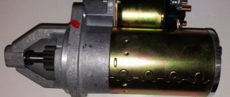
Electric starter on the MTZ tractor
The gasoline engine is a small, single-cylinder starting internal combustion engine. The manufacturer delivers the PD-10 model from the factory. It consists of a motor and a gearbox. People sometimes call it “launcher”. The launcher's power is only 10 horsepower. Considering that this is a two-stroke engine, a mixture of gasoline and oil is used as fuel. Moreover, you can use low-quality fuels and lubricants - the engine is unpretentious, and this will not particularly affect its performance. After starting the PD-10, the torque is transmitted through the gearbox to the crankshaft of the main engine to spin it up.
Electrical diagram of the MTZ 82 tractor
The electrical equipment of the MTZ 82 tractor is intended for starting and maintaining the engine, powering electrical appliances and other devices, as well as for operating the tractor and agricultural machinery at night, both when performing agricultural work and when using the tractor for transport work.
The rated voltage in the system is 12 V. The tractor electrical system includes:
- a) sources of electrical energy - batteries and an alternating current generator working in conjunction with a relay regulator;
- b) engine starting system - electric starter with remote activation; starter relay relay wiring diagram, additional resistance control element of the electric torch heater; electric torch heater; 3-position heater and starter switch;
- c) lighting and light signaling - front and rear lights; front direction indicators; tractor rear lights, brake lights and direction indicators; license plate light; instrument panel indicator lamps; cabin lighting; portable lamp; turn signal relay; central switch and light switches;
- d) electric motor of the cabin air heating and cooling unit with a switch;
- e) an electric motor with a windshield wiper and a switch;
- f) connecting panels; plug connectors; wiring harnesses and fuse blocks;
- g) instrumentation - indicators of water temperature and oil pressure; ammeter; air pressure gauge; tachospeedometer
Transmission of the MTZ 82 tractor
The transmission is designed to transmit torque from the diesel engine to the drive wheels of the tractor, power take-off shafts, as well as to change the magnitude and direction of revolutions and transmitted torque.
The MTZ-82 tractor uses a stepped transmission, which consists of the following main mechanisms: clutch; Transmission; rear drive axle with final drive, differential and final drives.
Also, the transmission of the MTZ 82 tractor includes a front drive axle with a main gear, a self-locking differential and wheel reducers, which are additionally driven by a transfer case and cardan drive.
Gear starter for MTZ
The design of the gear unit is distinguished by the transmission of torque from the armature through a built-in gear reducer, which, with its gear ratio, increases the torque power to the diesel flywheel. This design of the unit has a smaller electric motor part, thereby reducing the cost of production of the unit. The idea of the design is to reduce the use of expensive electric steel, magnets, and copper in assembly parts during production and increase the profitability of sales.
For the consumer, the advantage is a lower consumed discharge current and a lower voltage drop in the network during startup, taking into account the increase in power due to the mechanical part of the unit. The use of a unit of this design has a positive effect on the battery charge life, which is important when starting is difficult in the cold season.
The market offers a number of units for MTZ 82 by the following popular brands:
- Slovak - Slovakia
- Atek - Belarus
- Jubana – Lithuania
- Magneton – Czech Republic
To eliminate biased assessments in the comparison of the above brands, we will not fall into a useless assessment based on a number of reviews on the Internet. Often, buyers' impressions can be based on the purchase of counterfeit units of low quality that discredit a particular brand. To select a unit, we will indicate a number of criteria that ensure the acquisition of a high-quality starter.
Criteria for choosing a starter
Today, the qualitative differences and advantages of components of absolutely all brands are determined by the quality of assembly parts manufactured to order in China. Each brand adheres to its own marketing strategy in sales, which determines the price level, service, technical and quality level of the units offered.
Suspension diagram for MTZ 82
The suspension is designed to hinge the traction frame with a blade to the main frame of the motor grader and ensure its installation of the blade in various positions that are necessary for the normal functioning of the machine.
The traction frame is suspended from the main frame at three different points. One of which is a ball pin that pivotally connects both frames - this is the front suspension along the motor grader.
There is also a rear suspension, which is carried out using two hydraulic cylinders for lifting the blade, hinged to two eyes of the clamp on the main frame of the motor grader, and ball joints of the transverse beam of the traction frame.
Hydraulic cylinders can either raise or lower the traction frame depending on their activation, and they also connect both frames.
Installing an electric starter instead of a starting motor
Depending on the specific operating conditions of the tractor and individual needs, the owners themselves determine the advisability of using either an electric starter or a starting motor. It would be more justified to start the engine using the PD-10 in cold weather, when the fuel has thickened and in order to start the engine, more power and more battery consumption are required. In summer or in warm areas, starting with a conventional starter is a more convenient option.
What should you do if you want to use the comfort and advantages of an electric starter over a starter motor?
There are several reasons for switching from using the PD-10 to the version with an electric starter. One of them is the need for constant refueling and maintenance of the starting engine. Who wants to constantly mix gasoline with oil, check the spark, and constantly turn the magneto themselves? In such cases, there is only one option left - to install an electric starter on the tractor. When such a decision is made, several nuances should be taken into account.
If you have enough free time and a desire to save money, then a suitable option is to use a kit of parts for conversion, which usually includes:
- The starter itself.
- New flywheel or flywheel ring.
- Adapter rear plate for starter.
In this case, the tractor will have to be “rolled out” to install the sheet and the engine “halved”. Most likely you will have to replace the clutch cover.
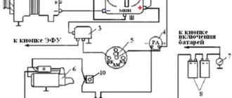
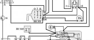
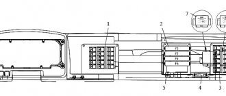
Connection diagram for RS 502 on MTZ-80/82 tractors : 1 – battery; 2 – socket; 3 and 4 – holding and retracting windings of the traction relay; 5 – resistor; 6 – auxiliary winding of relay RB1; 7 – rectifier device; 8 – switch VK-403; 9 – switch VK316-B; 10 – spiral glow plug; 11 – generator; 12 – additional resistance SE50-V; 13 – control element PD50-V; GC – main contacts; OO – main winding; SP – consumers; EP – to the coil of the solenoid valve of the torch air heater; LC – contact for turning on the control lamp; K1 – normally closed contacts of relay RB1; K2 – normally open contacts of the PC502 relay.
For those who do not have the time and desire to disassemble the tractor to such an extent, as well as in cases where the level of knowledge makes you doubt your abilities, it is better to use ready-made mechanisms that are offered by many manufacturers. Such devices have an undoubted advantage over the method described above - they do not require disassembling the engine to replace the clutch and flywheel, their installation takes much less time and involves removing the starting motor and installing an adapter with a starter in its place.
Electrical wiring of the MTZ 82 tractor and its color scheme
» Electrical equipment » Electrical wiring of the MTZ 82 tractor and its color scheme
The electrical wiring of the MTZ 82 tractor is made according to a single-wire electrical circuit, in which the metal parts of the tractor act as the “ground”, i.e. the second wire. This wiring diagram provides a much smaller number of wires and generally simplifies the electrical system, but at the same time requires careful attention to the insulation of the wires, as well as the reliability of their fastening. Damage to the wire insulation can lead to short circuits, causing fuses to malfunction, insulation burning, and the tractor catching fire.
The electrical circuit of the tractor uses low-voltage wires of the PGVA brand with PVC insulation of various colors. The wires are assembled into bundles that are mounted and connected using special mounting and installation devices (connecting panels, plug connectors, etc.).
Wiring maintenance involves careful monitoring of the condition of insulation, contact connections and timely repair of damage. Pay special attention to the cleanliness and fastening of wires.
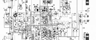
Colored wiring diagram of the MTZ 82 tractor
Download full poster (1.5 MB)
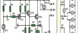
Basic problems in engine starting systems
Any engine starting system for MTZ tractors requires maintenance, and in case of malfunction, repair.
There are several possible malfunctions of the electric starter:
- The starter does not turn on. If there is no doubt about the serviceability of the device itself, then you should look for the reasons in the electrical circuit of the tractor. The switch may be faulty or the wiring may be broken. It is necessary to check, if necessary, clean and tighten fasteners and terminals.
- When the starter is turned on, the engine cranks slowly. The reason may be insufficient battery charge or inappropriate oil for the season. The brush contacts may be broken. In this case, the starter is disassembled, the commutator is cleaned, the brushes are changed and the brush springs are adjusted.
- If the starter armature rotates, but does not turn the crankshaft. Most likely the freewheel is slipping. This leads to inevitable replacement of the starter drive.
- After starting the engine, the starter does not turn off. This may be a consequence of drive jamming, sintering of relay contacts, short circuits of relay winding turns, or bearing wear. In these situations, the starter must be removed to accurately determine the cause of the failure. If necessary, replace bearings, traction relay, etc.
- One of the common malfunctions is the lack of engagement of the starter bendix with the flywheel crown. Most often this is due to contamination of the Bendix mechanism itself, and is eliminated by washing it in gasoline. After that, you need to manually turn the gears and you can install them in place.
It is important to remember that the performance of the starter, like any other mechanism, depends on the prevention of malfunctions.
For MTZ tractors, monthly maintenance periods have been established that the owner must comply with. As a result, the lifespan of all tractor systems will increase significantly.
electrical equipment MTZ-80, old-style color wiring diagram
Tractor owners are wondering what the MTZ-82 electrical circuit is. The Minsk Tractor Plant produces agricultural machinery that is known far beyond the borders of Belarus. The use of Belarus MTZ-1221, MTZ-80 and 82 units has become widespread in agriculture and construction.
What is an MTZ electrical circuit?
Let's look at what the electrical equipment diagram of a Minsk tractor consists of. One of the advantages of Minsk technology is the use of high-quality electrical wiring, based on the fact that metal parts are designed to act as mass. The advantages of such electrical wiring MTZ-1221 include:
- reduced number of wires;
- simplified approach to maintenance.
But you need to take into account that wiring requires constant care and monitoring.
This will help monitor the serviceability of the wires, their insulation, and the reliability of the fastenings. If damage to the electrical circuit of the MTZ tractor is not detected in time, a fire, insulation damage, failure of electrical circuits, etc. may occur.
Let's consider the electrical equipment of Belarus tractors and a description of its operation. The electrical circuit of the MTZ-1221 has the following characteristics:
- It has a polyvinyl chloride colored surface with low voltage.
- Additional elements are connecting panels, connectors, and wires that can be mounted in bundles. For example, such a half-move is applied to wires in MTZ-82.
- The PS 300A-100 socket is located on the rear wall of the operator's cabin and has 7 contacts.
- The socket is intended for all work where electricity is needed, including when transporting goods.
- Connection to the socket is made via a plug.
- If the need arises, you can connect the wiring harness from other units. Both the plug and the socket have special markings that help you understand where the wires are connected.
Thus, the wiring of MTZ-80, 82 and 1221 is functional and is designed to withstand loads while the tractor is operating.
Starter in the tractor electrical circuit
A mandatory element of the electrical equipment of Minsk tractors is a starter, which is activated by a color scheme. The starter consists of the following elements:
- Electrical engine;
- drive unit;
- relay;
- switch.
Engine power is 4.8 hp. The MTZ-82 electrical circuit ensures the operation of a starter DC motor, which is made of series excitation coils. All coils have 4 poles.
To turn on the starter, the developers installed a special switch. It is located on the control panel in the operator's cab. The engine starts due to the fact that power comes from the battery. The torque from the shaft is gradually transmitted to the crankshaft, which is associated with the operation of the drive gear with the flywheel.
Electrical circuit maintenance
Maintenance of the tractor circuit can be done with your own hands or with the help of an electrician. The main thing is that this happens regularly and that all terminals and fastenings are checked. If necessary, it is necessary to clean the necessary parts from dirt and dust.
The starter requires cleaning every 3000 hours of use. To do this you need to do the following:
- dismantle the starter;
- remove dirt;
- remove the casing that performs protective functions;
- check the brush-commutator assembly.
Then the starter must be reassembled and the insulation on the wires, the connections on the plugs, and the integrity of the wires checked.
The collector is an end-face type, made of a copper plate and reinforced with plastic type AG-4.
The cover is made of zinc alloy, four brush holders are riveted to it.
The brushes are trapezoidal in shape; their reliable contact with the commutator is ensured by the force of cylindrical springs, isolated from the “ground” to exclude the possibility of current passing through them. Insulated brushes with field winding coils are connected using plugs.
The armature shaft rotates in plain bearings pressed into the covers, as well as into the intermediate support.
The starter motor is powered by batteries. By turning the ignition key, the relay electromagnet is connected to the power circuit, draws in the armature, the movement of which is transmitted through the rod and lever to the starter drive.
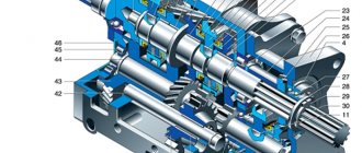
Rice. 112. Starter 24.3708: 1 – housing; 2 – anchor; 3 – excitation coil; 4 – brush; 5 – collector; 6, 19 and 25 washers; 7 and 17 – covers; 8 – brush spring; 9 – connecting bus; 10 and 30 – plungers; 11- pull-in relay coil; 12 – relay holding winding; 13 – relay anchor; 14 – return spring; 15 — relay flange; 16 – lever; 18 – persistent half ring; 20 – clip; 21 – drive gear; 22 — freewheel; 23 – buffer spring; 24 – branch sleeve; 26 — intermediate support; 27 – outer ring; 28 — roller; 29 – spring; 31 coupling covers.
The drive is mounted on the armature shaft and consists of a gear, a roller freewheel with a guide sleeve, a buffer spring and a release sleeve.
The freewheel transmits torque in only one direction - to the diesel shaft, ensuring automatic separation of the starter and diesel shafts after start-up and thereby protecting the starter armature from destruction.
When the starter is turned on, the torque of the armature shaft is transmitted to the guide sleeve of the freewheel and from it to the outer race. Turning clockwise, the cage is jammed by the rollers and continues to rotate along with the smooth cylindrical surface of the gear. Springs hold the rollers in the narrow part of the shaped grooves of the outer race. Together with the outer race, the gear and crown of the diesel flywheel begin to rotate. After starting, the rotation speed of the flywheel and gear increases. The rollers are carried along by the cylindrical part of the gear, move into the wider part of the shaped grooves of the outer race and wedge the surfaces. This eliminates the transmission of torque from a running diesel engine to the starter armature.
The electromagnetic traction relay engages the drive gear with the diesel flywheel crown and supplies power to the electrical part of the starter. The relay is mounted on a cast flange connecting it to the cover on the drive side. When the relay is turned on, its pull-in (serial) and holding (shunt) windings create a magnetic field, the force of which forces the armature into the cavity between them. The movement of the armature is transmitted through the rod and lever to the drive, which moves along the helical splines of the armature shaft, and its gear meshes with the flywheel ring. At the end of the stroke, the relay armature presses the plunger, the contact disk of which closes the main contacts of the relay, connecting the starter to the battery. At the moment the main contacts are closed, the series winding is excluded from the current circuit, and the armature of the traction relay is held in the retracted position only by the shunt winding.
If it happens that the gear teeth touch the ends of the flywheel teeth, it will stop, but the switching lever will move by the force of the compressed buffer spring, which will allow the relay contacts to close. The starter will begin to rotate, and as soon as the gear rotates, the compressed spring will engage it with the flywheel ring. While the starter is operating, the relay contacts remain closed under the action of the holding winding and open only after the traction relay is turned off. In this case, by the force of the return spring, the drive gear will be disengaged from the flywheel ring, the relay armature will return to its original position, the main relay contacts will open, and the starter will turn off.
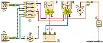
When the starter switch is in the start position, voltage from the battery is applied to the PC502 relay coil connected to ground. The relay is triggered, its contacts close, and through them power is supplied to the starter traction relay. The latter turns on and turns the crankshaft of the diesel engine, with an increase in the rotation speed of which the generator voltage increases, converted by the built-in rectifier and supplied to its winding. When the voltage increases to 8...9 V, which corresponds to a rotation speed of 10.8...12.5 s-1 (650...750 rpm), the relay is triggered, opens its contacts, and is de-energized. After the contacts open under the action of the spring, the starter is turned off.
Starter maintenance involves checking the reliability of its fastening and the condition of the terminal connections. Every 500 operating hours, check the condition of the commutator and brushes using a clean rag soaked in gasoline, remove dirt from the surface of the commutator, first lifting the brushes so as not to get dirt on them. After one TO-3, and subsequently after two TO-3 (approximately after 3000 operating hours), the starter is removed from the tractor and cleaned of dust and dirt. Then remove the protective casing and check the condition of the brush-collector assembly. Contamination or slight burning of the collector is eliminated with a clean rag soaked in gasoline. If the burn cannot be removed, these areas should be cleaned with glass sandpaper. The brushes must move freely in the brush holders and be adjacent to the commutator with their plane. The pressure force of the springs on the brushes at the moment of separation should be 29.4 + 2.45 N (3.0 ± 0.25 kgf). After this, remove the cover from the traction relay and check the condition of the contacts. If the contacts are burnt, they should be cleaned with a file and wiped with a rag soaked in gasoline.
In case of more serious malfunctions, the starter should be disassembled and the following work performed: - clean the internal and external surfaces of the housing, covers and armature from dust and dirt; - grind the collector and then clean it with sandpaper (80...100 grit); — check the condition of the drive gear and flywheel ring, clean out the teeth or gouges with a file, and if the wear is great, replace the parts with new ones; — turn the contact bolts 180° in case of severe burning, and turn the contact disk over to the other side; — replace worn brushes with new ones; - lubricate all rubbing parts (bearings, screw splines and armature shaft journals, drive bushings) with CIATIM-201 lubricant or engine oil.
The starter, assembled after the above operations, must be adjusted and tested in operation. When adjusting, a voltage of 8 ... 12 V is supplied to the output terminal of the relay windings from a special unit or battery. The starter housing is securely connected to the negative terminal of the battery. To prevent the starter armature from rotating, bus 9 is disconnected from the housing output bolt. When the switched-on traction relay is activated and the armature is in the “On” position, i.e., pulled into the winding, the gap between the end of the drive gear and the thrust half-rings on the armature shaft should be 3 ± 1 mm. The gap is adjusted by turning the eccentric axis of the lever 16, which is then secured with a nut.
The build quality of the starter is checked by testing it at idle. The starter is connected to the current source with wires (cross section 5.0 mm2) of approximately the same length as on the tractor. The battery must be in good condition and charged at least 75%.
During the test, the armature rotation speed and current consumption are measured and their compliance with the technical characteristics of the starter is ensured: rotation speed is not less than 83.3 s-1 (5000 rpm), current strength is not more than 150 A.
Tight rotation of the armature, which is usually caused by distortions as a result of improper assembly, the armature touching the strips, short circuits of the armature winding to ground or short circuits between turns lead to high current consumption and a decrease in rotation speed.
Low current consumption and a reduced rotation speed at normal voltage at the starter terminals indicate poor contact at the wire connections or a decrease in the force of the brush springs.
Electrical diagram of the MTZ-80L/82L tractor
Category - Electrical equipment
Electrical diagram of the MTZ-80L/82L tractor
- headlight
- front turn signal
- water temperature indicator sensor
- connection panel
- instrument panel plug connector
- sound signal
- relay regulator
- generator
- Heating-cooling unit switch
- heating-cooling unit electric motor
- lamp switch
- lampshade
- indicator lamps for turning on the “ground”, high beam and direction indicators
- wiper switch
- wiper
- tachospeedometer
- indicator lamps for turning on the “ground”, high beam and direction indicators
- headlight switch
- instrument lighting lamps
- starter switch
- central switch
- windshield washer
- stop switch
- tail light
- back light
- connection panel
- rear light switch
- instrument panel plug connector
- plug socket
- license plate light
- windshield washer switch
- direction indicator switch
- indicator lamps for turning on the “ground”, high beam and direction indicators
- ground switch
- portable lamp socket
- accumulator battery
- starter lock switch
- horn button
- magneto switch button
- turn signal relay
- ammeter
- water temperature indicator
- fuse blocks
- starter motor
- magneto
- starter spark plug
- starting heater solenoid valve
- starting heater motor
- starter heater glow plug
- starting heater switch
- control heating coil for starting heater
- starting heater switch
- fuel level indicator
- fuel gauge receiver