The hitch is a universal equipment for connecting a tractor with mounted, semi-mounted and trailed type machines in working and transport positions. The device is a mechanical part of the tractor’s hydraulic linkage system, consisting of a system of articulated parts combined into a structure that ensures reliable connection and the specified position of the working parts of the devices and machines used. MTZ tractors are standardly equipped with a rear linkage; additionally, the machines can be equipped with a front linkage to place attachments at the front. The technical characteristics of the MTZ 80(82) linkage correspond to a load capacity of at least 3.2 tons.
MTZ hitch with towing device
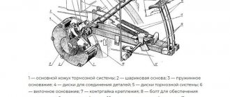
Rear linkage device
The structure is attached to the rear wall of the tractor rear axle housing. The upper rotary shaft of the hitch is placed with its axis in the cylindrical supports of the bracket, which is bolted to the upper edge of the rear wall of the axle housing. The central part of the shaft interacts through a splined connection through a lever 7 with a power hydraulic cylinder 6 , which provides lifting and lowering. On the left and right sides of the shaft there are lifting levers 5 connected to the corresponding left and right, vertically placed, length-adjustable braces 3 and 9 . The braces are connected to the lower longitudinal strips 4 and 10 .
Rear linkage device MTZ 80
The connection is made pivotally with fingers through forks 2 . With their front ends, the longitudinal left and right lower bars are attached to the edges of the axle installed in the lower part of the rear axle housing. The rear ends are equipped with spherical hinges 1 for convenient connection with the towbars of attached machines. Additionally, the lower bars are equipped with length-adjustable ties 12 . To ensure the connection of attachments and machines, the design includes a central upper rod 8 with connecting ball joints at the ends. Its front part is connected to the positioner bracket, the rear part is attached to the mounted device. In the standard configuration, a transverse bar 13 with a towing eyelet with a locking pin is hingedly attached to the rear ends of the lower bars for attaching towbars of machines and vehicles.
Considering the location of the attachment points of the lower longitudinal bars to the axle body, the MTZ rear linkage has a three-point design, which provides a fairly rigid attachment to the tractor without lateral movement of the attachment. This connection requires the obligatory deepening of the working tillage implements of the mounted machine when the unit turns.
Three and two point mounting schemes
Description and characteristics
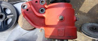
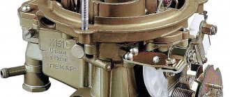
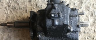
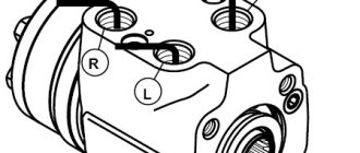
The MTZ 82 linkage cylinder is the most important component of the design of the working mechanism; it is used to hold it in a certain position, raise, lower, and perform various tasks. A similar element is used for the correct operation of attachments, as well as trailed devices. This kind of element has the identification number ts-100x200-3, which makes it easy to find it in the spare parts catalog. Among the characteristics of such a product it is worth noting:
- weight - 22 kg;
- nominal/maximum pressure - 16/20 MPa;
- working cylinder diameter - 10 cm;
- piston stroke - 20 cm;
- rod - 4 cm;
- nominal/maximum operating speed - 0.15-1 m/s.
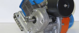
It should be mentioned that a cylindrical element of this type has a wide range of applications; it is used in popular models of tractors MTZ 50, 80, 82, as well as YuMZ-6, which makes the components interchangeable. The hydraulic cylinder model is of the piston type and has a two-way operating principle. Moreover, it is made according to an outdated model, which is currently practically not used in new technology. It is called the main one because it is used to perform most tasks.
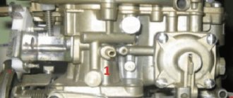
In addition to the above-mentioned cylinder, the design of the product contains 2 more similar elements with a diameter of 7.5 cm. This kind of product is called remote, since they are mounted on the body of the unit, and communication with the main hydraulic system is carried out through special pipelines and hoses.
Device
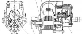
It should be noted that all cylinders installed in the tractor design are completely identical to each other in their operating principle and technical design, and their main difference is the size of the parts. When studying the structure of the main hydraulic cylinder, it is advisable to highlight several key elements of its design. Among them:
- frame;
- back and front covers;
- rod cavity and fork;
- oil line;
- piston and rod;
- MTZ 82 hydraulic cylinder mounting bracket, studs and valves.
The internal structure of the product deserves a more detailed consideration. The body appears to be a special pipe, the inside of which has been processed. It is sealed by means of rings, which are located in the corresponding cavities of the back and front covers. The studs provided by the design are used to securely connect such elements to the body, and a fork is located at the end of the back cover. It is important to remember that the cylinders with a diameter of 7.5 cm use cast iron as the material for the cover, while the main hydraulic cylinder uses high-strength steel. The oil required for the operation of the mechanism enters through the corresponding hole located in the front cover. The cylinder of the MTZ tractor is constructed in such a way that when the rod is retracted, the attachment is lifted. The stop in the extreme position does not interfere with the movement of the rod, but helps move the valve to a special place on the product cover.
If desired, the owner of tractor equipment from MTZ can adjust the stroke of the rod. This will allow you to use the unit when working with equipment that requires restrictions when lifting the attachment. Similar manipulations may be required when using devices that work with a connection to the rear power take-off shaft.
Adjustments
The position of the mounted machine is adjusted by changing the length of the braces 3.9 and the upper central link 8 . The braces adjust the transverse arrangement of the attachments. Standardly, the left brace is not adjusted; adjustment is made by changing the length of the right brace, equipped with a handle 15 for convenient rotation of the screw. The position of the machine in the longitudinal position relative to the horizon is adjusted by changing the length of the upper central link.
The tension of the couplers connected to the longitudinal lower links and the tractor body adjusts the lateral movement of the attachment relative to the axis of movement of the tractor. Loose ties allow for slight movement. To ensure a rigid position of the machine, for example, for inter-row cultivation of crops or during sowing with a mounted seeder, the couplers are tensioned as much as possible, eliminating lateral rocking.
For convenient adjustment of length and tension, threaded pairs of screws and ties have left and right threads. The tie rods are secured with control nuts.
An increase in load capacity is achieved by installing additional pins at the connection of the brace forks and longitudinal bars in additional holes located closer to the rear mounting hinges. In this case, the forks must be turned with the grooves forward so that the forks do not affect the pins connecting the ends of the lower longitudinal rods. To ensure reliable fastening of connections in the hinge joints, it is necessary to use standard locking pins and cotter pin nuts for the tension bolts of the structure.
Trouble-shooting
The main problems are the wear of the hinge joints of the braces and bars, as well as the splined joints of the rotary shaft and lifting levers. Increased gaps do not allow the structure to be fixed in the desired position and complicate the adjustment process when adjusting the depth of processing and the accuracy of the movement of working tools mounted on agricultural implements. cars Elimination of increased play in joints is achieved by replacing worn parts. In some cases, welding and subsequent machining of worn surfaces to the required dimensions are used.
Maintenance of the structure consists of lubricating the rotary shaft through standard oilers, monitoring the integrity of parts, as well as regularly checking the reliability of hinged and threaded connections.
Reasons for lowering the hitch
The cause is a malfunction in the tractor's hydraulic system. In addition to the usual oil leakage from the system, one of the main reasons is wear of the piston and rod seals of the hitch's power cylinder. The development in the seals of the unit allows oil to flow from the lifting cavity to the lowering cavity and the cylinder rod changes its position, lowering the linkage. The second reason for lowering is a malfunction of the hydraulic distributor as a result of debris or general contamination. If flushing does not eliminate the cause, the unit is sent for repair.
Features of repair of hydraulic cylinder MTZ 82
To repair the hydraulic cylinder, dismantling the unit can be done in two ways: when removing the right wheel and right fuel tank, or through the cabin when removing the driver's seat through the hatch underneath.
After disassembling, it is important to carry out defect detection of the assembly parts. Particular attention should be paid to the wear and condition of the working surface of the cylinder and the degree of wear of the rod. It is not allowed to operate a cylinder on the working surface of which there are holes, burrs or areas of uneven wear. If more than 0.1-0.2 mm wear on the cylindrical surface of the rod is detected, the part is replaced with a new one. Also, the rod is replaced or adjusted if a part deflection of more than 0.1 mm is detected. The threads in the mounting holes of the assembly parts and the elements connecting the cylinder to the hydraulic system line are not allowed. It is recommended to replace all sealing elements of the unit with new ones when carrying out repairs.
Automatic hitch SA 1 (Triangle)
A device for automatically attaching machines on MTZ 80(82) “Automatic coupler SA 1” (the so-called “triangle”), is attached by three points to the hitch - two hinges of the ends of the lower longitudinal bars and the central link. The contact connecting part of CA 1 is made of a metal profile in the shape of a triangle. Fixation is carried out with a spring lock with a latch. When hanging, the triangle fits its profile into the internal profile of the triangle of the machine being hung. With the upper guide angle 8, the device, when connected, aligns the hole of the outer triangle with the spring-loaded latch 4 of the triangle on the tractor. If a match is made, the latch closes automatically under the action of a spring. To disconnect the mounted device, press down the lock lever 9 and disengage the triangle 3 by lowering the linkage. The drive of the control lever for the coupling device lock is brought out using a cable 10 to the driver's seat to ensure operation without outside help.
Automatic coupler SA 1 on the MTZ 80 hitch
The CA 1 device is universal and is used in mounted systems of tractors of different brands.
The MTZ 82(80) hitch has a similar design to all wheeled tractors of the MTZ family and universal row-crop machines of the YuMZ-6, T-40, T-25 brands. Additionally, the hitch of modern tractors can be equipped with a lift-type towing device, as well as towing devices of various designs. Crawler tractors are equipped with a reinforced hitch with the possibility of two or three point connection of the hitch to the tractor.
Hydraulic cylinder TsS100-200-3, Hitch MTZ-80/82, YuMZ-6, GC100.40x200.01
| Hydraulic cylinder of rear linkage MTZ, YuMZ old model | |
| Catalog number | Ts100x200-3, GC100.40x200.01, Ts100-200-3, TsS-100 |
| Application | rear linkage of the MTZ-50, MTZ-80, YuMZ-6, MTZ-82 tractors without FDA |
| Purpose | for controlling the working parts of technological equipment of tractors |
| Peculiarities | double-acting piston, old style |
| Weight | 22 kg |
Technical characteristics of the cylinder Ts-100x200-3 (expand)
| Nominal pressure, MPa | 16 |
| Maximum pressure, MPa | 20 |
| Cylinder diameter, mm | 100 |
| Rod diameter, mm | 40 |
| Piston stroke, mm | 200 |
| Nominal speed, m/s | 0,15 |
| Maximum speed, m/s | 1,00 |
| Hydromechanical efficiency | 0.94 MTZ-80 and the principle of operation of the hydraulic cylinder Ts100x200-3 for the MTZ-80, YuMZ-6 attachment |
Source