03.03.2022 12 113 Transmission
Author: Victor
It is necessary to adjust the clutch on KamAZ 5320 and other models to maintain the good condition of the truck. Sometimes the need to carry out such work may arise on the road, so it is advisable for the car driver to know the basic conditions for independently and correctly setting up the mechanism.
[Hide]
Design features of the clutch
The bulk of KamAZ trucks use a double-disc clutch with a radial arrangement of power springs. To operate the mechanism, a hydraulic drive with a pneumatic amplifier is used. Thanks to this design, the force required to press the clutch pedal is significantly reduced. During the operation of KamAZ, wear occurs on the clutch discs, which must be compensated for by adjustment. Correct adjustment of the mechanism ensures the fuel consumption declared by the factory and confident acceleration of an empty or loaded vehicle.
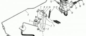
KamAZ clutch drive mechanism diagram
The main components of the drive, which is shown in the photo, are:
- pedal (1);
- hydraulic unit (2) with reservoir (3);
- highway (6);
- executive pneumatic cylinder (16).
The KamAZ clutch of models 55111, 5320, as well as 43118 and 740 consists of the following structural units:
- clutch housing (A);
- release disc with stamped metal casing (B);
- pressure springs (B) and levers (D);
- one drive disk (E);
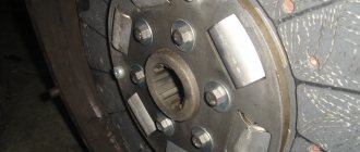
- two driven disks (D) with linings (W).
Clutch diagram for KamAZ 740 with diesel engine
The driven discs in the clutch design of a KamAZ truck are made using heat-resistant friction linings, which ensure a long service life of the mechanism. The design of the disks provides a damper for vibrations that occur when the motor shaft rotates. The drive pedal is mounted on special bushings and rarely requires lubrication during operation.
On more modern KamAZ models, single-disc clutches of the so-called Euro type are used. This mechanism is found, for example, on models 6520 or 4308. The supplier of elements for such units is Sachs, and amplifiers made by Wabco are used. There are several clutch models that differ in the amount of transmitted torque. One of the differences between imported amplifiers is the built-in indicator of friction lining wear. Wear is measured by the distance between the amplifier body and the washer on the rod. When the linings are completely worn out, this distance ranges from 23 to 25 mm. In this case, driving a car is still possible, but repair work must be carried out urgently.
Wabco CCGT unit, the wear indicator rod is visible in the upper left part
On some KamAZ models, for example, on 43114, there may be a PGU manufactured by the Volchansky Automotive Unit Plant, in which there is no possibility of adjusting the rod. Typically, such a PGU is either replaced with a customizable one or another rod with adjustability is installed.
Device
In a double-disc clutch (diagram 1), the driving parts are the engine flywheel 13, the casing 7, the pressure plate 8 and the drive plate 11, the driven parts are driven discs 9 and 12, the activation parts are springs 6, the release parts are levers 4 and the release clutch 5 with a release bearing.
Scheme 1 – Double-disc friction clutch
1, 6 – springs; 2 – bolt; 3, 10 – fingers; 4 – lever; 5 – coupling; 7 – casing; 8 – pressure disk; 9, 12 – driven disks; 11 – drive disk; 13 – flywheel
The casing 7 is attached to the flywheel 13 and is connected to the pressure 8 and drive 11 disks by guide pins 10, which fit into the grooves of the disks. As a result, the pressure and drive disks can move freely in the axial direction and transmit torque from the flywheel to the driven disks mounted on the splines of the gearbox input shaft.
How is the adjustment carried out?
If problems occur with the clutch, you should try to make adjustments. When disc slippage occurs (sluggish acceleration, slight burning smell), it is necessary to set the correct clutch stroke.
If the disks are not fully spaced (difficult switching), you will have to perform more operations:
- Set the pedal stroke.
- Remove air from the drive lines.
- Check the liquid level in the PSU.
When using the Euro unit, only the pedal free play needs to be adjusted. Lubrication and adjustment of other clutch parts during operation of the machine is not provided, except for monitoring the height of the fluid level in the drive reservoir.
By adjusting the clutch on KamAZ 5320 and other models we mean setting the correct gap between the release plate plane and the lever heads, as well as adjusting the free play of the pedal and drive clutch. The permissible free play for the clutch pedal must be in the range from 6 to 12 mm.
The gap is understood as the distance between the points of the central part of the pedal platform when the pedal is released and at the moment the master cylinder begins to turn on. The free play is regulated by rotating the eccentric pin located in the connection of the pedal lever with the upper eye of the amplifier rod. The adjustment is made with the pedal tension spring fully depressed, i.e. the pedal should rest against the upper rubber buffer, which serves as a travel limiter.
For example, on KamAZ 65115 the do-it-yourself adjustment process is as follows:
- Unlock the pin castle nut pin.
- By rotating the finger you need to achieve acceptable free play.
- Tighten the nut and secure it with a cotter pin.
- Check the pedal's full travel. If everything is adjusted correctly, it should be between 185 and 195 mm.
On single-disc MFZ units, the adjustment is similar, but the pedal travel should be from 140 to 150 mm.
Below, the process of adjusting the free wheel is demonstrated using the example of KamAZ 4310, the author of the video is Vladimir Krasikov.
_______________________________________________________________________________
Clutch of Kamaz-5320 vehicle and its components
The Kamaz-5320 clutch consists of a mechanism and a drive and has the following design features: – the Kamaz-5320 clutch mechanism has a device for automatically setting the middle drive disk to the middle position when the clutch is disengaged. This device does not require adjustment during operation; – the shape of the casing ensures fixation of the pressure springs; – the driven disk has a heat-resistant friction lining with a long service life; – the clutch pedal is suspended, which does not violate the seal of the cabin, and the metal-plastic bushings in the pedal supports do not require replenishment of lubricant. The Kamaz-5320 clutch mechanism (Fig. 1) consists of a housing 20, a pressure plate (basket) with a casing 17, pressure springs 16 and release levers 6, two driven disks 1 with friction linings 22 and torsional vibration dampers; middle drive disk 2. The stamped Kamaz-5320 clutch casing is installed on the flywheel using two mounting sleeves 3 and secured with ten M10 and two M8 bolts. The Kamaz-5320 drive disks, pressure 4 and middle 2, have four spikes on their outer surfaces, which fit into special grooves in the flywheel and transmit engine torque to the friction surfaces of the driven disks, the hubs of which are installed on the splines of the drive shaft of the gearbox or divider. Between the housing 17 of the Kamaz-5320 clutch and the pressure plate 4 there are pressure springs 16, under the action of which the driven and middle drive disks are clamped between the pressure plate and the flywheel. The middle drive disk of the Kamaz-5320 has a lever mechanism 27. It automatically sets disk 2 to the middle position when the clutch is disengaged. The Kamaz-5320 clutch release device consists of 4 pull-off levers balanced on a pressure plate with a thrust ring 14, a clutch release clutch 12 with a thrust bearing 10 mounted on the bearing cover of the drive shaft of the gearbox or divider, and a release fork 13 located on the shaft in the crankcase clutch (divider). The Kamaz-5320 clutch drive (Fig. 2) consists of a clutch pedal 1 with a release spring 11, a master cylinder 2, a compensation tank 5 with working fluid, a pneumohydraulic booster, 18 pipelines and hoses for supplying working fluid from the master cylinder to the clutch booster and air supply from the pneumatic system to the clutch booster.
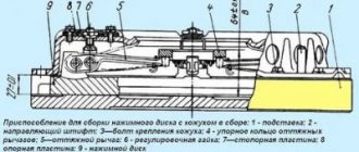
Fig.1. Clutch KamAZ-5320 1 – driven disc; 2 — leading middle disk; 3 — installation sleeve; 4 – pressure disk; 5 — release lever fork; 6 — release lever; 7 – thrust ring spring; 8 — coupling lubrication hose; 9 — spring loop; 10 — release bearing; 11 – release spring; 12 — clutch release; 13 — clutch release fork; 14 - thrust ring; 15 — fork shaft; 16 — external pressure spring; 17 — clutch casing; 18 — heat-insulating washer; 19 — casing mounting bolt; 20 — clutch housing; 21 - flywheel; 22 — friction lining; 23 – internal pressure spring; 24 – input shaft; 25 - torsional vibration damper disk; 26 — internal spring of the torsional vibration damper; 27 — external spring of torsional vibration damper; 8 — driven disk ring; 29 – mechanism for automatically adjusting the position of the middle drive disk. The pneumohydraulic drive booster of the KamAZ-5320 serves to reduce the force on the clutch pedal. It is secured with two bolts to the clutch housing flange (divider) on the right side of the power unit.
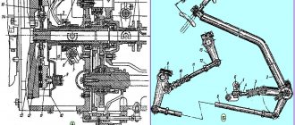
Rice. 2. Drive of the Kamaz-5320 clutch mechanism 1 – pedal; 2 – main cylinder; 3.10 – upper and lower stops; 4 – bracket; 5 – compensation tank; 6 – hydraulic pipeline; 7 – lever; 8 – piston pusher; 9 – eccentric pin; 11 – tension spring; 12 – plug; 13 – pipeline; 14 – air release valve; 15 – spherical adjusting nut; 16 – pneumatic piston pusher; 17 – protective cover; 18 – pneumatic hydraulic booster; I – compressed air When you press the Kamaz-5320 clutch pedal, the fluid pressure from the master cylinder is transmitted through pipelines and hoses to the clutch pneumatic booster to the hydraulic piston and to the piston of the follower device, which automatically changes the air pressure in the power pneumatic cylinder of the booster in proportion to the force on the clutch pedal. During operation, as the linings of the driven discs wear out, the clutch drive should be adjusted to ensure free movement of the clutch release clutch. Adjustments of the KamAZ-5320 clutch Adjustments of the KamAZ-5320 clutch during service: - tighten the mounting bolts of the pneumatic amplifier of the clutch drive: - check by external inspection the tightness of the clutch drive, if necessary, eliminate the leak and bleed the hydraulic system of the drive; — check the action of the release springs of the clutch pedal and the clutch release fork shaft lever, and if necessary, correct the faults; — adjust the clutch drive; — lubricate the clutch release clutch bearing and the clutch release fork shaft bushing; — check the fluid level in the clutch compensation tank and top up if necessary; — drain the condensate from the air-hydraulic booster by unscrewing plug 12 (see Fig. 3). Adjusting the Kamaz-5320 clutch drive consists of checking and adjusting the free travel of the clutch pedal, the free travel of the clutch release clutch and the full travel of the pneumatic hydraulic booster pusher. Checking and adjusting the free play of the Kamaz-5320 clutch release clutch is carried out by manually moving the fork shaft lever from the adjusting spherical nut 15 of the pusher 16 of the pneumatic hydraulic booster of the clutch drive (in this case, it is necessary to disconnect the spring from the lever). If the free play of the lever, measured at a radius of 90 mm, turns out to be less than 3 mm, then adjust it with the spherical nut of the pneumatic hydraulic booster pusher to a value of 3.7... 4.6 mm, which corresponds to the free play of the clutch release 3.2... 4 mm. Then check the full stroke of the pusher of the Kamaz-5320 pneumatic hydraulic booster by pressing the clutch pedal all the way, while the full stroke of the pusher must be at least 25 mm; with a smaller stroke, complete disengagement of the clutch is not ensured. If the pusher stroke of the Kamaz-5320 pneumatic hydraulic booster is insufficient, check the free play of the clutch pedal, the amount of fluid in the master cylinder (Fig. 3) and the clutch reservoir, and if necessary, bleed the clutch hydraulic system. The free play of the pedal, corresponding to the start of operation of the master cylinder, should be 6 ... 12 mm. It should be measured in the middle part of the clutch pedal area. If the free play is outside the limits specified above, adjust the clearance A between the piston and the master cylinder piston pushrod. Adjust the gap between the piston and the piston pusher of the Kamaz-5320 main cylinder using eccentric pin 9 (see Fig. 3), which connects the upper eye of the pusher 8 with the pedal lever 7. Adjust the gap when the release spring presses the clutch pedal to the upper stop 10. Turn the eccentric pin so that the movement of the pedal from the upper stop until the pusher touches the piston is 6... 12 mm, then tighten and cotter the castle nut. Lubricating the Kamaz-5320 clutch. Lubricate the clutch release fork shaft bushings through two grease nipples 5, and the clutch release clutch bearing through grease nipple 6, making no more than three strokes with a syringe. Otherwise, excess lubricant may get into the clutch housing. Check the fluid level in the compensation tank of the master cylinder visually. The normal liquid level in the tank corresponds to 15...20 mm from the top edge of the tank. The total volume of fluid in the Kamaz-5320 hydraulic clutch is 380 cm3. During service C (autumn), change the fluid in the clutch hydraulic system.
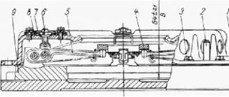
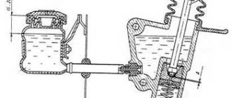
Rice. 3. Pneumatic booster KamAZ-5320 1 - spherical nut: 2 lock nut; 3 — clutch release piston pusher: 4 — protective cover: 5 — clutch release piston; 6 — follower piston body: 7, 21, 24, 26 cuffs; 8 — bypass valve; 9 — breather; 10 membrane of the tracking device; 11 — membrane seat; 12 — plug: 13 — return spring; 14 — air supply cover; 15 — valve stem; 16 — inlet valve; 17 — exhaust valve; 18, 22 — membrane and piston springs; 19 — front body; 20 — pneumatic piston; 23 — piston seal housing; 25 — spacer spring; 27 — rear body; I — brake fluid supply; II - air supply The main cylinder of the Kamaz-5320 clutch consists of a pusher, a housing, a piston, a compensation tank and a tank cover. Repair of the Kamaz-5320 clutch. Bleed the hydraulic system of the Kamaz-5320 clutch drive after eliminating leaks in the hydraulic drive in the following order: - Clean from dust and If the rubber protective cap of the air release valve 14 (see Fig. 3) becomes dirty, remove it and put the rubber hose supplied with the car onto the valve head. Dip the free end of the hose into brake fluid poured into a clean glass container. — Press the clutch pedal sharply 3...4 times, and then, leaving the pedal pressed, unscrew the air release valve 1/4...1/3 turn. Under the influence of pressure, part of the liquid and the air contained in it in the form of bubbles will come out through the hose. — After the liquid stops coming out, close the air release valve. — Repeat the operations according to paragraphs. 2 and 3 until the release of air from the hose completely stops. During the bleeding process, it is necessary to add brake fluid to the system, not allowing its level in the compensation tank of the master cylinder to decrease by more than 2/3 of normal in order to avoid atmospheric air entering the system. After bleeding is complete, with the clutch pedal pressed, screw the air release valve all the way in and only then remove the hose from its head and put on the protective cap. Next, set the normal fluid level in the master cylinder. The brake fluid that is released from the hydraulic system during pumping can be used again after settling and subsequent filtration. The quality of pumping is determined by the full stroke of the pneumatic hydraulic booster pusher. Check for condensation in the power cylinder of the air-hydraulic booster. To drain the condensate, unscrew the plug in the aluminum housing of the air-hydraulic booster. To drain completely, lightly press the clutch pedal. At least once every three years, it is recommended to flush the clutch drive hydraulic system with industrial alcohol or clean brake fluid, disassemble the master cylinder and pneumatic power steering and refill with fresh brake fluid. Wash the hydraulic system pipelines with alcohol or brake fluid and blow them with compressed air, having first disconnected both ends. Before assembling, moisten the pistons and cuffs of the hydraulic system with brake fluid. Replace defective (hardened, damaged working edges and worn) cuffs and protective covers. When replacing the pneumatic hydraulic booster of the Kamaz-5320 clutch drive to remove the pneumatic hydraulic booster: - release air from circuit IV of the auxiliary brake system drive and other consumers through the valve on the receiver; — remove the release spring of the clutch release fork shaft lever, disconnect the air piping of the air-hydraulic booster, the hydraulic hose and drain the fluid from the hydraulic drive system; — Unscrew the two bolts securing the pneumatic hydraulic booster and remove the booster with the rod. To install the Kamaz-5320 pneumatic hydraulic booster: - align the mounting holes with the holes in the clutch housing and secure the booster with two bolts and spring washers; — connect the hydraulic hose of the pneumatic power steering and the air pipeline: install the release spring of the clutch release fork shaft. Pour brake fluid into the master cylinder compensation tank and bleed the hydraulic drive system. Check the tightness of the pipeline connections (leaking of brake fluid from the connections is not allowed); if necessary, eliminate the leakage by tightening or replacing individual elements of the connections. Check and, if necessary, adjust the gap between the end of the cover and the travel limiter of the gear divider valve rod. When removing the KamAZ-5320 clutch from the engine after disconnecting the gearbox, first screw four M10x1.25x62 coupling bolts into the pressure plate until it stops in the casing, and then unscrew the bolts securing the clutch casing to the flywheel and remove the casing with the pressure plate assembly, the middle and driven discs clutch. In case of replacing individual parts of the KamAZ-5320 clutch, adjust the position of the thrust ring of the retracting arms before installing it on the engine. To adjust the KamAZ-5320 clutch, install the pressure plate assembly and secure it to the control stand (Fig. 4) or to the flywheel with an insert, ensuring the installation dimension A = (29 + 0.1) mm, and loosen the tightening bolts. The correct position of the thrust ring is determined by the mounting dimension B = (54 + 0.3) mm, the runout of the end T2 relative to T1 should be no more than 0.2 mm. If the position of the thrust ring is violated, adjust the position of the ring on the device using nuts 3, restoring dimension B, while the supporting surfaces of all four pull-off levers must simultaneously touch the thrust ring. Do not adjust the position of the thrust ring using the specified nuts on the engine. Before installing the KamAZ-5320 clutch on the engine, place 15 g of lubricant 158 into the cavity of the front bearing of the drive shaft, located in the crankshaft. Install the Kamaz-5320 clutch using a splined mandrel, ensuring the coaxial arrangement of the axes of the driven disks with the axis of the crankshaft. Pay attention to the correct relative position of the driven disk hubs - with short protruding ends facing each other. The Kamaz-5320 middle drive disk assembly should move easily in the grooves of the flywheel under the action of the pull-out levers. Install the KamAZ-5320 pressure plate (basket) with the casing assembly on the engine flywheel also without additional adjustment, but without distortions, achieving this by uniformly tightening the fastening bolts with a torque of 54... 61.8 Nm (5.5... 6.3 kg/ cm). After the bolts securing the casing to the flywheel are tightened, remove the tightening bolts from the pressure plate. The runout of the thrust ring of the retraction arms relative to the axis of the crankshaft should be no more than 0.5 mm. Rice. 4. Pressure disk (basket) KamAZ-5320 with casing assembly 1 - control stand; 2 - bolt; 3 — adjusting nut; 4 — locking plate; 5 - thrust ring; 6 - coupling bolt: A - installation size; B—installation size; T1, T2 - end runout
_______________________________________________________________________________
_______________________________________________________________________________
_______________________________________________________________________________
- Clutch KamAZ-5320 and its components
- Repair of PGU and Kamaz clutch master cylinder
- Gearbox gearbox KamAZ 141
- Gearbox gearbox KamAZ ZF 16
- Gearbox 152 Kamaz with divider
- Gearbox gearbox 154 Kamaz
- Gearbox Kamaz-4308
- Clutch of a Kamaz-4308 car
- Clutch and gearbox KamAZ-65115
- Disassembly and assembly of Kamaz-4310, 55111, 43118 gearboxes
_______________________________________________________________________________
- Cylinder block, head and valves Kamaz-740
- Fuel system of Kamaz-740 diesel engine
- Adjustments and repairs of fuel injection pump Kamaz-740
- Drive axles of the Kamaz-4310 vehicle
- Repair of Kamaz drive axle gearbox
- Rear axle KamAZ-4308
- Axles and suspensions of Kamaz-65115 dump trucks
- Installation of Kamaz cardan shafts and axles
- Repair of Kamaz vehicle transfer case
- Kamaz power steering - adjustments and repairs
- Repair of Kamaz steering gear parts
- Steering parts Kamaz-4308
- Parts of the brake system Kamaz-4308
- Brake system and brake drive Kamaz
- Repair of brake valves and Kamaz compressor
- Suspension Kamaz-4310, 55111, 43118 and their parts
- Frame and suspension of the Kamaz-4308 car
- Cabin details and platform KamAZ-65115
- Cabin components Kamaz-4308
- Platform mechanism of Kamaz vehicles
- Klintsy KS 65719-5K truck crane based on KamAZ-6522 chassis
- Truck crane KC-35719-7-02 based on Kamaz-43118 chassis
- Truck crane Galichanin KC-55713-1K based on KamAZ-65115 6x4
- Ivanovets KS-45717K-1/1R truck crane based on KamAZ-65115 chassis
- Ivanovets KS-3577-3/4 truck crane on KamAZ-43253 4x2 chassis
Clutch debugging
The next stage of adjustment will be to adjust the free play parameters of the clutch, the value of which should be from 3.2 to 4 mm. The measurement is carried out by rotating the adjusting nut.
The sequence of actions in this case:
- Loosen the fork mounting nut.
- Unscrew the fastening pin, allow it to move freely and remove it.
- Rotate the traction fork until the required clearance is obtained.
- Tighten the nut and install the pin in place.
- Install the locking pin.
- Check the setting. When the pedal is fully depressed, the clutch stroke should be at least 25 mm.
Debugging the full stroke of the amplifier pusher
Before starting to debug the mechanism, it is necessary to find out the stroke length of the pusher. To do this, you need to completely disengage the clutch and measure the stroke. If its value is 25 mm or less, then the clutch will not disengage completely. The driver will notice this problem immediately by the difficulty of shifting gears. To find the cause of the problem, you need to check the level of working fluid in the pusher cylinder. The standard volume is 380 cubic meters. see. If the level of the substance is insufficient, it should be topped up.
Hydraulic system diagram
Using the KamAZ 5511 model as an example, adding fluid is done as follows:
- You need to open the reservoir cap located on the drive housing.
- Add liquid to a level 15-20 mm below the edge of the neck.
The second reason for unsatisfactory operation of the amplifier may be air in the system. In this case, the drive system must be bled. This procedure is somewhat more complicated.
On KamAZ 55102 for this you need:
- Add fluid to normal level.
- Remove the protective cap from the bypass valve (installed on the CCGT housing), put on a rubber hose and lower it into a container with liquid.
- Sharply press the clutch pedal all the way.
- Open the valve one turn and press the pedal until the substance stops bubbling at the outlet of the hose. In this case, it is necessary to constantly add new fluid to the supply tank, not allowing it to fall below the 40 mm mark from the top of the tank.
- Close the valve, remove the hose and replace the cap.
- Add fluid to the operating level.
- To control the quality of work, you must press the pedal all the way - the pusher stroke should not be less than 25 mm.
Malfunctions and what to do
Repair of the KamAZ clutch can be delayed if the machine is regularly maintained.
Load, road surface, driving skills affect the intensity of destructive processes:
To identify malfunctions, before adjusting the clutch drive, the automobile clutch is diagnosed:
- Inspect the drive for leaks, determine the degree of destruction of the pedal springs and fork lever.
- Bring the distance of free movement of the cylinder pusher and the fork axle lever to the recommended parameters.
- Lubricate the balls of the release collet and the clutch fork shaft.
- Determine the liquid level in the main cylinder tank and adjust the amount to normal.
- Tighten the bolts of the pneumatic booster device.
- Change the fluid in the hydraulic drive circuit once a year.
Clutch malfunctions are eliminated as the linings of the drive discs wear out.
If it slips
If the mechanism does not turn on completely, the car accelerates slowly or loses power when climbing the highway, or a burnt rubber smell is heard, then there is an explanation for the problems:
- there is no clearance between the bearing pressing on the basket petals and the stop ring;
- oil has leaked between interacting surfaces;
- friction gaskets have become unusable;
- the clamping springs have lost their shock-absorbing qualities or are broken.
Adjusting the KamAZ clutch basket
By adjusting the clutch basket we mean adjusting the tabs placed on the basket. This debugging can be done with the box removed or adjusted directly on the car.
When performing the task without removing the box, you will need a homemade tool, which is a 3.5 mm thick wire with a 20 mm long end bent at a right angle. Using such an improvised feeler gauge, check the gap between the release bearing and the support ring of the clutch feet. The gap is adjusted using a nut on the PSU rod. You can bring the paws to the ring through the hatch in the upper part of the clutch housing. At the same time, it is important to ensure that the paws fit as uniformly as possible to the surface. But it is more correct and reliable to adjust the clutch removed from the engine.
To do this you need:
- Place the assembled pressure plate on the template, which will provide a gap of 29 mm.
- Loosen the mounting bolts.
- Set the position of the stop ring for the feet. All four paws should touch the ring at the same time.
- Check the runout of the working surface of the disk.
- Lubricate the front bearing located in the crankshaft.
- Install the clutch using a mandrel, which will ensure alignment of the mechanism discs and the engine shaft.
This adjustment is carried out only with a double-disc clutch. A unit with one disk does not need such adjustment.
The video from the Auto and Moto channel shows the removal of the clutch and clearly shows the design features, as well as the drive for the operation of the mechanism.
Principle of operation
When the clutch is engaged, springs 6 act on the pressure plate, clamping the drive and driven discs between it and the engine flywheel.
When the clutch is disengaged, clutch 5 presses on levers 4, which, through pull pins 3, move the pressure plate away from the engine flywheel. In this case, the necessary gaps are created between the flywheel, driven, drive and pressure disks, which is facilitated by release springs 1 and adjusting bolts 2.
In double-disc clutches, the compression of the driving and driven parts can be carried out by several coil springs , evenly spaced in one or two rows along the periphery of the pressure plate. Compression can also be provided by a single central conical spring .
Maintenance
In addition to settings, the clutch of KamAZ vehicles requires regular maintenance, since this significantly increases the service life and reliability of the mechanism on all KamAZ brands.
Using model 53215 as an example, maintenance consists of the following main points:
- Checking the tightness of the amplifier mounting bolts in the clutch drive circuit.
- Monitoring the tightness of hydraulic lines. There should be no oil stains on them.
- General check of serviceability of pedal assembly parts. All elements must be in good condition and not have large gaps in the connections.
- Checking the presence of lubricant in the clutch bearing and fork connection bushing. To supply oil in the clutch housing there are three points equipped with grease nipples. Oil is injected into them using a syringe.
- Draining condensate from the CCGT housing.
- Checking the fluid level in the amplifier reservoir.
When is clutch replacement required?
If all the work performed does not lead to the restoration of the clutch mechanism, then this becomes one of the signals to replace it.
Other signs of critical wear of structural elements are:
- sudden turning on of the disks, resulting in a hard jerk of the car;
- difficulty engaging all gears, accompanied by a characteristic crash;
- sluggish acceleration of the car, while the engine speed clearly does not correspond to the selected gear and speed;
- smell of burning pads when driving.
If such problems occur, it is necessary to stop moving as soon as possible and repair the mechanism. Continued operation of the vehicle with faulty or burnt-out clutch discs will lead to failure of the gearbox.
Types of clutch (classification)
The operating principle of a dry clutch is based on the friction force that occurs when dry surfaces interact: drive, driven and pressure plates. This force creates a rigid connection between the engine and the gearbox.
The most common type of clutch is a dry single-plate clutch. It is used on most cars with a manual gearbox. A wet clutch creates friction surfaces in an oil bath and ensures smoother contact between the discs; cooling due to fluid circulation and transmitting more torque to the transmission. The wet clutch is used on modern robotic gearboxes and is more expensive and difficult to manufacture than the dry clutch.
In general, the classification of clutch includes the following types:
- by control method - with mechanical, hydraulic, electric or combined drive (for example, hydromechanical);
- by type of friction - dry (when the friction linings work in air) and wet (when the friction linings work in an oil bath);
- by switching mode – permanently or not permanently closed;
- by the number of driven disks - single, double or multi-disk;
- by type and location of pressure springs - several cylindrical springs are placed along the periphery of the pressure plate and with a central diaphragm spring.
- according to the number of torque transmission streams - single- or double-stream.
Photo gallery
The photographs below show some elements of the clutch drive system of a KamAZ truck.
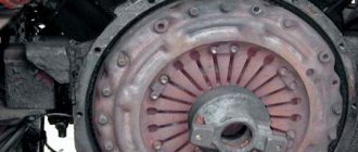
Conventional double disc clutch
Euro single disc clutch
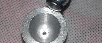
Classical PSU
Clutch cylinder, the rod for the pedal and the fitting for supplying fluid to the PSU are clearly visible
Learn more about the operating principle of a double-disc clutch
The release bearing presses the release levers, which pull back the pressure plate. He moves away from the first slave and releases the release springs. These springs, in turn, release the intermediate drive disk, and it moves away from the second friction disk due to other release springs. The same amount as the pressure disk moved away from the first friction disk.
During reverse movement, the release springs ensure uniform pressing of the intermediate disk against driven No. 2, and the pressure disk against driven No. 1. The pressure plates move along studs that are screwed into the flywheel, and the clutch basket is attached to them. These studs also have release springs.
In double-disc clutches, compression of the driving and driven parts can be provided by several coil springs, which are evenly spaced in 1 or 2 rows along the periphery of the pressure plate. Compression can also be provided by a single central conical spring.
Often, a double-disc clutch is driven by a pneumatic booster, which is needed to reduce the effort applied to the clutch pedal.
Video “Adjusting the clutch on KamAZ”
The video, shot for the Auto and Moto channel, demonstrates the adjustment of the clutch installed on a KamAZ 740 diesel engine.
Do you have any questions? Specialists and readers of the AUTODVIG website will help you ask a question
Was this article helpful?
Thank you for your opinion!
The article was useful. Please share the information with your friends.
Yes (88.89%)
No (11.11%)
X
Please write what is wrong and leave recommendations on the article
Cancel reply
Rate this article: ( 10 votes, average: 4.70 out of 5)
Discuss the article: