What and how much should I put in the T-25 (in the box and in the hydraulics)?
Questions can only be asked after registration.
Please login or register. Tell me, who pours what and, most importantly, in what volume into the T-25 (into the box and into the hydraulics)?
I pour 8 liters of VMGZ oil into the hydraulics. https://moskva.regmarkets.ru/masla-gidravlicheskie-24370/maslo-yo-9e21689. I fill the box with TSP-15K oil, about 15 liters.
Tractors: T-25 and KUBOTA L-2402.
I pour 8 liters of VMGZ oil into the hydraulics. https://moskva.regmarkets.ru/masla-gidravlicheskie-24370/maslo-yo-9e21689. I fill the box with TSP-15K oil, about 15 liters.
I filled the box with Enius semi-synthetic. less howling.
TUM 25A, MTZ 1221, MTZ 82.1.
I pour 8 liters of VMGZ oil into the hydraulics. https://moskva.regmarkets.ru/masla-gidravlicheskie-24370/maslo-yo-9e21689. I fill the box with TSP-15K oil, about 15 liters.
I filled the box with Enius semi-synthetic. less howling.
So on TSP the box doesn’t howl much.
Tractors: T-25 and KUBOTA L-2402.
and before you pour in the new one, what should you use to wash off the old one and how?
I washed it with gasoline
and before you pour in the new one, what should you use to wash off the old one and how?
The best thing is to pour a mixture of gasoline and kerosene or death oil. Just don't be sorry. I drove it for a bit and drained it.
TUM 25A, MTZ 1221, MTZ 82.1.
I washed it with gasoline
Even you are being harsh, colleagues, I hope you don’t wash the engine with such liquids
try to live without malice and without envy, and not look for reasons for offense. you will smile, just for joy - a smile will not harm anyone!
I washed it with gasoline
Even you are being harsh, colleagues, I hope you don’t wash the engine with such liquids
wash the motor. (I did this once after purchasing it) I drained half the oil or a little more, and filled the oil with 6 liters (it turned out above the level), started it, ran it for 15-20 minutes, drained it
I washed the brake bands and the gearbox with solvent. seals do not leak
and a box. seals do not leak
this is not just a matter of seals, gasoline and solvent completely wash out the remaining oil from rubbing pairs, for example from a bushing-shaft or gear-shaft pair, and such liquids themselves do not have lubricating properties, and after changing the oil, all these pairs will run dry for now fresh lubricant will not penetrate there, and it is not at all necessary but also possible that seizure or scuffing can occur; by the way, I myself for some time restored the functionality of the brakes of my just purchased tired tractor by pouring a little gasoline into the sleeves and rinsing the drums and belts
try to live without malice and without envy, and not look for reasons for offense. you will smile, just for joy - a smile will not harm anyone!
and a box. seals do not leak
this is not just a matter of seals, gasoline and solvent completely wash out the remaining oil from rubbing pairs, for example from a bushing-shaft or gear-shaft pair, and such liquids themselves do not have lubricating properties, and after changing the oil, all these pairs will run dry for now fresh lubricant will not penetrate there, and it is not at all necessary but also possible that seizure or scuffing can occur; by the way, I myself for some time restored the functionality of the brakes of my just purchased tired tractor by pouring a little gasoline into the sleeves and rinsing the drums and belts
In order for there to be sticking or scuffing on the rubbing elements (without oil), they must be heated to a temperature so that they begin to stick. which is not entirely real. (firstly, oil channels go to such places, thirdly, gasoline will evaporate there faster)
in the past, 2 glasses of gasoline were poured into the UAZ at night (in winter) before turning it off, so that the oil would be liquid in the morning, start it, and after the oil warms up above 70 degrees, all the gasoline evaporates
Hydraulic system of tractor attachments T-25
________________________________________________________________________
The hydraulic system of the T-25 tractor attachments is intended for hanging and controlling agricultural machines and implements (lifting to transport position and lowering to working position). It consists of a hydraulic system and a rear linkage. The hydraulic system of the T-25 attachment is a separate-unit double-acting system, equipped with standard hydraulic units installed in various places on the tractor and connected to each other by metal and rubber oil lines.
Rice. 62. Diagram of the hydraulic system of the T-25 tractor attachments
1 — power cylinder; 2 - locking device; 3 - distributor; 4 — breather; 5 - dipstick; 6 — hydraulic lift housing; 7 - drain plug; 8 — hydraulic system filter; 9 - oil pump. The hydraulic diagram is shown in Fig. 62. The pressure in the system is created by gear pump 9, which sucks oil from tank 6 and supplies it under pressure to distributor 3.
Rice. 63. Location of hitch units on the T-25 tractor
1 — hydraulic lift housing; 2 - filter; 3 — oil pump and its drive; 4 - distributor; 5 - oil line; 6 — rear linkage; 7 - cylinder. Next, oil can enter the upper or lower cavity of power cylinder 1, depending on the position of the distributor spool, and move the piston in the appropriate direction. The oil also drains from the cylinder through a distributor into the tank. The placement of hydraulic units on the tractor is shown in Fig. 63.
Hydraulic pump for attachments T-25
The NSh-10 gear oil pump operates at an operating pressure of 100 kg/cm2, and has a capacity of 14 liters per minute if its drive shaft rotates at a speed of 1565 rpm. The pump (Fig. 64) consists of a housing 22, a cover 4, two drive gears 13 and a driven 10, two bearings 9 and 12, rubber sealing cuffs 8 and a plate 7. A rubber o-ring 6 is installed between the housing and the cover. The cover is fixed relative to the housing two pins 5 and is attached to it with eight bolts. The pump housing of the T-25 tractor has borings in which bearings and gears are located. Bearings serve as supports for gear shafts and also seal the end surfaces of the rims. The bearings are paired bushings. Each bearing has two borings for the journals of the mating gears.
Rice. 64. Hydraulic oil pump NSh-10 of the T-25 tractor and its drive
1 - plug; 2 — power fork roller; 3 - coupling bolt; 4 — hydraulic pump cover; 5—locating pin; 6 - sealing ring; 7 - plate; 8 — figured cuff; 9 — front bearing; 10 — driven gear; 11 — hydraulic pump housing; 12 — rear bearing; 13 - drive gear with shaft; 14 — frame oil seal; 15 - movable coupling; 16 - ball; 17 — splined bushing; 18 — gasket; 19—locating pin; 20 - segment key; 21 — drive roller with ball holder; 22 - ball bearing; 23 - cover; 24 - bolt; 25 — driven gear; 26 — drive housing; 27 — power plug. Both bearings 9 and 12 are floating (self-aligning) and are pressed to the ends of the gears independently under the influence of oil pressure. High-pressure oil from the injection cavity is supplied through the channel between the bearings and the housing, pressing them against the ends of the gears. At the same time, the working ends of the bearings are exposed to high oil pressure from the discharge cavity. The bearings are evenly pressed against the ends of the gears, thereby eliminating the gaps that arise as a result of wear of the ends of the gears and bearings. The gear journals are lubricated from the suction cavity through spiral grooves located in the bearing bores on the unloaded side. The drive end of the drive gear is sealed with a frame oil seal 14 with a self-clamping cuff. The NSh-10 pump is non-reversible. It can be used for left-hand rotation only or right-hand rotation only. The T-25 tractor uses a hydraulic pump NSh-10 of left rotation (counterclockwise, when viewed from the drive shaft). Straight couplings are installed on the side surfaces of the housing to connect the suction and discharge pipelines. The inscription “Input” is cast on the body on the side of the suction hole. The oil pump is secured with four bolts to the drive housing, which is mounted on the connecting housing on the right side of the tractor. The drive consists (Fig. 94) of a housing 26, a gear transmission and an enabling device. The driven gear 25, installed in the drive housing on two bearings 22, is in constant mesh with a gear located in the connecting housing of the tractor behind the clutch release device and connected directly to the engine flywheel. Thus, this gear, and therefore gear 25, is constantly rotating when the engine is running. To disconnect the NSh-10 pump, a ball clutch is used. The driving element of the coupling is a roller 21. A gear 25 is secured to it using a key 20. A hinge holder is located at the rear end of the roller. Four balls 16 are placed in its holes. Inside the holder there is a splined sleeve in the splined hole of which the drive shaft of the hydraulic pump is installed. On the outer surface of the sleeve 17 there are four grooves into which balls 16 can fit. They are buried in the grooves of the sleeve 17 and are held in this position by the inner surface of the sleeve. This position corresponds to the engaged state of the clutch, in which the balls close the holder on the roller 21 with the sleeve 17 and transmit rotation from the drive to the hydraulic pump of the T-25 tractor. If you use fork 27 to move the bushing to the left, then a recess of larger diameter will be located opposite the balls. This allows the balls, under the influence of centrifugal forces, to disengage with the grooves of the sleeve 17 and disconnect the gear 25 from the hydraulic pump shaft (on position). Fork 27 sits on shaft 2 and is clamped by bolt 3. At the outer end of the shaft there is a handle with a button that locks the shaft in the on or off position. It is allowed to turn on the NSh-10 pump only with the engine running, since when the roller 21 with the holder does not rotate, the balls may not coincide with the grooves on the sleeve and will prevent the sleeve 17 from moving to the right.
Hydraulic lift of attachment system T-25
The T-25 hydraulic lift consists of a cast iron body on which a hydraulic system filter, a lifting mechanism, a power cylinder and a bracket for attaching the front hinge of the central link are mounted. The shaft of the lifting mechanism rotates in the bushings of the upper part of the hydraulic lift and has at the ends two lifting levers connected by braces to the longitudinal rods of the suspended system, and one power lever connected to the upper head of the cylinder rod. All these levers are connected to the shaft by splines and rotate with it. A PTO is mounted in the lower part of the T-25 hydraulic lift body. Inside the cast housing of the hydraulic lift (in its upper part) there is an oil tank of the hydraulic system, into which oil is poured (Fig. 65).
Rice. 65. Hydraulic lift of the attachment system T-25
1 — breather; 2 — filter plug; 3 - gasket; 4 — filter housing cover; 5 — cover gasket; 6 - valve seat; 7 - ball valve; 8 — filter spring; 9 — valve spring; 10 - filter glass; 11 — filter element; 12 — body; 13 - hole for installing the lift shaft. The oil drains from the distributor into the filter housing. It is a set of ten standard filter elements 11 used in the hydraulic systems of all domestic T-25 tractors. The filter is located in a stamped glass 10, installed in a cast iron housing 12 and pressed against the end of the cover 4 by a spring 8. The filter has a safety valve 7, which opens when the filter element screens are clogged, and passes oil into the tank past the filter. The filter works as follows. Through the drain pipe, the oil fills the filter bowl, seeps through the mesh, is filtered and, entering the central tube, is drained from its open end into the tank. If the filter elements are clogged, the pressure in the filter bowl increases to 1-1.5 kg/cm2. Oil under this pressure opens the ball valve 7, overcoming the force of the spring 9, and enters directly into the central filter tube, bypassing the filter elements, and from there it is drained into the tank. To fill the tank with oil, there is a filling hole in the upper part of the filter cover, closed with plug 2. On the opposite side of the T-25 hydraulic lift there is a breather filled with gimp (wire entanglement). The breather connects the tank to the atmosphere, but prevents oil from splashing out and protects the tank from contamination with dust when the tractor is operating. There is a drain plug at the bottom of the tank on the right. A plug with a dipstick is located next to the breather.
Power cylinder of the T-25 tractor
The power cylinder has a diameter of 75 mm and a piston stroke of 110 mm (Fig. 66). The lower cylinder hinge is a fork molded into the bottom cap. The upper hinge is located at the end of the rod 6. The fingers of these hinges are fixed in the axial direction with spring cotter pins. The body of the hydraulic cylinder of the T-25 attachment system consists of a steel sleeve 17 and two covers: upper 18 and lower 16, tightened together with four coupling bolts. Rubber sealing rings are installed at the points where the pipes meet the covers. A piston 11 moves inside the hydraulic cylinder, fixedly fixed to the rod 6 with a nut 14. The piston has a sealing device consisting of one rubber ring of circular cross-section and two rings 13 made of leather or plastic compound of rectangular cross-section. A rod sealing device is mounted in the top cover of the T-25 power cylinder, consisting of a rubber ring and a set of thin (0.3 mm) steel scraper washers 8, tightly covering the rod and cleaning it from dust and dirt when the piston is lowered.
Rice. 66. Power cylinder of the hydraulic system of attachments T-25
1 - locking device; 2 — cylinder lever; 3 - hose; 4 — hydraulic lift housing; 5 — limiter stop; 6 — piston rod; 7 — tie rod; 8 - guillemots; 9 - valve; 10 - valve body; 10 - piston; 12 — cuff; 13 - sealing ring; 14 - nut; 15 — bypass tube; 16 — lower cylinder cover; 17 — cylinder liner; 18 — top cylinder cover; 19 — rod seal; 20 - retarding valve; 21 — washer; 22 — pin; 23 — retarding valve body. Oil is supplied from the distributor to the upper or lower cavities of the T-25 hydraulic cylinder through steel oil lines, which end in rubber hoses 5, allowing the hydraulic cylinder to deviate at a certain angle when raising or lowering the piston. The supply is made through the top cover of the cylinder. For greater versatility, the cover has two holes for connecting hoses on the outside and inside. This allows the hydraulic cylinder to be placed on the tractor in various positions and oil to be supplied from both the upper and lower covers. The unused pair of holes is closed with plugs with tapered threads. On the T-25 tractor, holes on the outside of the cover are used for oil supply, and the opposite holes are plugged. Oil enters the upper cavity of the power cylinder directly through the drillings in the cover. Oil enters the lower cavity through another system of drillings in the upper cover, then through tube 15 connecting the upper and lower covers, and through the drillings in the lower cover for the piston. In the path of this oil flow is a valve, which is designed to limit the lowering of the piston to some part of the full stroke. When oil is supplied to the lower cavity of the T-25 hydraulic cylinder (the “lift” position), the oil flows through the drillings in the upper cylinder head under valve 9 and, lifting it, flows freely under the piston. The valve has a stem that extends out through a hole in the cover parallel to the stem in close proximity to it. There is a movable stop 5 on the rod, which can be secured with a clamp anywhere on the rod. If it is necessary to limit the lowering of the implement and at the same time maintain the automatic return of the spool to the neutral position, then the stop on the rod is installed and secured so that at the end of lowering it presses on the valve and feeds it into the seat. As soon as the valve seat is partially blocked, the flow of oil coming out of the lower cavity of the T-25 hydraulic cylinder will completely close the valve, lowering it by 10-15 mm. The piston will stop immediately after the valve begins to close, since at this moment the oil cannot escape from under the piston. A gap of 10-15 mm is formed between the stop on the rod and the outer valve stem. When the piston stops, the pressure in the upper cavity will increase, and the automatic distributor will return the spool to the neutral position. When the implement is subsequently raised, oil from the distributor will flow under the valve, open it and begin to flow under the piston; the gun will rise.
T-25 Attachment System Hydraulic Line Components
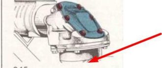
At the junction of the metal oil line with the flexible rubber hose of the T-25 hydraulic system, a shut-off device is installed that prevents oil from flowing out of the steel oil line and the rubber hose when disconnected (Fig. 67). The device consists of two balls 6 supported by springs 5 in each of the oil lines. When the oil lines are open, the balls are pressed against the sockets and close the oil outlets from the oil lines.
Rice. 67. Locking device of the T-25 attachment system
1 — steel oil pipeline; 2 - fitting; 3 — shut-off valve body; 4 — cross; 5 - spring; 6 — valve balls; 7 — connecting nut; 8 — hose shut-off valve body; 9 — union nut 10 — nipple; 11 — crimp coupling; 12 - rubber hose. In this position, part of the ball sphere protrudes above the plane of the body end. Therefore, when the oil lines are connected and the ends of the housings are in close contact, the balls, resting against each other, compress the springs and open the free passage of oil from one oil line to another. The retarding valve of the T-25 hydraulic system is installed in the fitting connecting the hose to the lower cavity of the power cylinder. It is designed to limit the speed of lowering the implement. The valve (see Fig. 66) consists of a plate washer 21 with a hole with a diameter of 2 mm and three limiting pins 22, pressed into the wall of the fitting and limiting the travel of the washer. When oil enters when lifting the T-25 attachment into the lower cavity of the cylinder, the washer is carried away by the flow of oil and, pressing against the pins, opens a free passage for oil. When lowering the implement, the oil moves in the opposite direction and presses the washer to the end of the fitting. In this case, the large hole is blocked, and oil flows only through a hole with a diameter of 2 mm, which limits the speed of lowering the implement. The rubber hoses connecting the metal oil lines to the T-25 hydraulic cylinder have an internal diameter of 10 mm. They consist of an inner rubber bladder, an outer rubber shell and a two-layer steel braid between them. The ends of the hoses 12 (Fig. 67) are reinforced with metal nipples 10, which are pressed into the hose and crimped externally with crimp couplings 11. The couplings are stamped with two annular grooves and are tightly fixed to the outer shell of the hose. The flange on the outer end of the coupling fits inside the groove on the nipple and prevents the nipple from being pulled out of the hose. Before installing it in the hose, a union nut 9 is put on the collar of the nipple, with which the hose is attached to the fittings of the power cylinder of the T-25 hydraulic system locking device. The outer thickened part of the nipple has a spherical shape. The sphere mates with the conical bore of the fitting and is pressed against it with a union nut. This pairing ensures reliable tightness in all connections of metal oil lines with rubber hoses. The same interfaces are used in connecting metal pipelines with shut-off devices. In this case, the tip, which has a spherical head, with a union nut pre-attached to its shoulder, is welded to the pipeline and pressed against the conical bore of the mating part.
Mechanism for attachments T-25
The T-25 attachment mechanism, or attachment system, is designed to connect the implement to the tractor, lift the implement, transport it when raised and lower it to the working position. The mounted system is made according to a three-point scheme, in which the implement is attached to the tractor at three points. The hinged system (Fig. 68) consists of two longitudinal rods 11 and 18, which are attached at the front ends to special cast side brackets 7 and 19, bolted to the main gear housing of the tractor; braces 10 and 16 connecting the longitudinal rods with the lifting arms 9 and 17 and the central rod. Mounted machines are attached to the rear ends of the longitudinal and central rods.
Rice. 68. Mechanism for attachments T-25
1 - upper hinge of the brace; 2 — brace screw stop; 3 - lock nut; 4 — brace screw; 5 — central thrust pipe; 6 — rear central link screw; 7 — right side bracket; 8 — lifting shaft; 9 — lifting lever right; 10 — right brace; 11 — right longitudinal rod; 12 — locking chain; 13 — rear beam; 14 — central thrust; 15 — chain bracket; 16 — left brace; 17 — lifting lever left; 18 — left longitudinal thrust; 19 — left side bracket; 20 — front longitudinal joint. There are ball joints at the front and rear ends of the longitudinal rods. The rod rotates freely to a certain angle in both the horizontal and vertical planes. The pin on which the rod rotates can be installed in the bracket in one of its three holes. The location of the pin installation depends on the modification in which the tractor is assembled (garden, vegetable or reduced modification). A special transverse beam 13 is installed in the holes of the rear ball joints of the longitudinal rods, to which the equipment is attached, or pins located directly on the frame of the T-25 hitch. Since the rear hinges are also ball joints, the mounted implement can move relative to the tractor arbitrarily at a certain angle in the horizontal and vertical planes. To limit the movement of the T-25 attachments, limiting or locking chains 12 are used. The chains have screw ties with which you can adjust their length. Installation of chains can be done in two versions. If it is necessary to ensure free movement of the implement in the transverse plane in the working position, but to limit its swinging in the transport position, then the chains are secured crosswise with the rear ends using brackets 15 to the longitudinal rods, and the front ends to the opposite brackets. In this case, when lifting the T-25 attachment, the chains are tensioned and limit its swinging. When the implement is lowered, the chains sag freely and do not interfere with the movement of the implement in the transverse direction. Sometimes free movement of the implement in the transverse direction is unacceptable. In this case, the chains are attached to the rods themselves in a cross shape and are tensioned so that the rods form a rigid system, movable only in the vertical plane. The braces provide the possibility of free movement in the range from 0 to 50 mm, which is necessary when operating the T-25 tractor with some wide-cut attachments. The free play is regulated by stops 2, screwed onto the threaded part of the brace and secured with castle nuts 3. The braces can be adjusted in length in the range from 435 to 492 mm. The upper hinge of the brace is movable in two mutually perpendicular planes due to the design of the traverse, which has pins connecting to the holes in the lifting arms. On these axles, the brace can move in the longitudinal plane. The T-25 brace rod fits into a roller installed in the traverse and having an axis of rotation in a perpendicular plane. This ensures the mobility of the brace in the transverse direction. The central link, like the longitudinal links, has ball joints at both ends. The central sliding rod is adjustable in length due to a threaded coupling with right and left threads and threaded shanks of the front and rear hinge. The coupling rotates using a removable knob passed through a hole in the middle of the coupling. The length of the central link of the T-25 linkage mechanism can be set in the range from 420 to 740 mm, which is achieved using replaceable threaded couplings - long and short, included in the kit of the mounted system.
The front center link joint is installed in one of several holes in a special welded bracket mounted on the hydraulic lift body.
________________________________________________________________________
________________________________________________________________________
________________________________________________________________________
________________________________________________________________________
- Spare parts catalog MTZ-80/82
- Spare parts catalog MTZ-1221
- Agricultural machinery
- Motoblocks and cultivators
techspez.ru
Features of the T-25
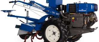
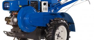
The T-25 tractor, which has the common name “Vladimirets”, is a 0.6 class traction unit. Available in various modifications. Used in agricultural work, in arable and sowing operations, for processing rows of agricultural crops. The machine can be equipped with trailed and mounted equipment.
The technical design of the car uses a D-2 diesel engine, which operates on the basis of a combined lubrication system. Most parts are processed under internal pressure, as well as by spraying. A pump is installed to ensure complete circulation of the material in the engine. The pump device operates from the crankshaft drive using gears and must be processed simultaneously with the motor.
Tractor T-25
- The main purpose of the tractor can be safely called performing various works using additional equipment. equipment. The latter, by the way, can be trailed, semi-mounted or fully mounted. Most modern tractors are characterized by a mounted hydraulic system, through which equipment is attached to the tractor; control is realized using levers (lifting to transport position or lowering to working position). Includes tractor rear linkage and hydraulic system.
The hydraulics of the T-25 tractor are used to lower or raise equipment mounted on this equipment to control dump trailers, implements, hydraulic units, etc. Traditionally, the hydraulic system includes an oil tank and an oil pump, one or more power cylinders , an oil line and a distributor through which the oil passes to the hydraulic units and is discharged back into the tank.The tractor hydraulics use disoil as a working fluid, which fills the internal space of the tank (hydraulic lift) located in the rear of the T-25. When entering from the distributor into the hydraulic lifter and when pouring, the oil is pre-cleaned by passing through the filter. If the filter is clogged, the oil enters the tank bypassing a special safety valve, which in this case opens. The oil level must be checked using a dipstick. The latter must have marks for the lower and upper acceptable levels.
T-25 hydraulic diagram
The given hydraulic diagram for t 25 includes:
- dipstick (5);
- distributor(3);
- drain plug (7);
- oil pump (9);
- power cylinder (1);
- locking device (2);
- hydraulic system filter (8);
- hydraulic lift housing (6).
breather(4);
Operating principle The gear oil pump generates pressure in the tractor hydraulics. It sucks oil from the tank and then supplies it under high pressure to the distributor. Then the oil will be supplied to the upper or lower cavity of the hydraulic cylinder (it all depends on what position the distributor spool is in) and move the piston in the desired direction. Next, the oil from the cylinder goes back into the tank through the distributor.
traktor-t25.com
Procedure for replacing lubricant
The T 25 tractor has technical features, so the oil is changed in accordance with a scheme that includes lubrication of almost all equipment that ensures the operation of the machine.
Oil in the T25 modification tractor is poured into the hole in the engine crankcase, which is located to the left of the front of the engine. To determine the required amount of liquid, you need to focus on the marks on the measuring base. The first check is performed 15 minutes after the engine has stopped running, when the material has completely settled from the walls to the bottom of the container.
To replace the level, remove the measuring rod, wipe it and reinsert it until it stops. After this, the measuring element is removed again and the mark of the wet segment is inspected.
Tractor oil is drained immediately after stopping the engine, so that the impurities included in the composition do not settle into sediment. To do this, a drain hole is opened on the bottom wall of the container, and the liquid is drained into the bowl.
If the oil is hot, protect your hands with gloves. For the replacement procedure to be effective, it is important to thoroughly rinse the housing, rotor, and centrifuge hood, remove metal dust from the flange magnet, and rinse the receiver grid from contamination.
Selection of lubricants for T-25/30 and DT-20
Dear friends, please share in this thread who is pouring what: -into the gearbox -into the engine crankcase -into the hydraulic system -into the on-board units According to the instructions:
Dear friends, please share in this thread who is pouring what: -into the gearbox -into the engine crankcase -into the hydraulic system -into the on-board units According to the instructions:
Into the engine crankcase? There is a good topic “OIL FOR TRACTOR ENGINES D-65, D-240, D-144” in https://fermer.ru/forum/rtm-remontno-traktornaya-masterskaya/80176. Just add D-21 to the name. TRANSMISSION OIL is poured into the gearbox and onboard gearboxes, mainly of the “GChS” brand - Gde Che Styril. According to the instructions, the hydraulic system is filled with oil of the same brand that is poured into the engine crankcase, but basically the same brand “GChS” from the series of motor oils is used.
Scheme for changing the oil in the engine of the T-25 tractor
The procedure is performed sequentially, taking into account the characteristics of the machine. To change the oil you need to do the following:
- Start the car engine.
- Raise the fuel temperature in the crankcase to +50°.
- Leave the engine.
- Drain the fluid from the crankcase.
- Clean the receiver from metal dust and install it in place.
- Wash the parts - housing, rotor, centrifuge - from contamination.
- Add fresh oil.
To find out which oil of which brand can be poured into the T 25 tractor, you should refer to the technical documentation for recommendations. Each manufacturer recommends several types of liquid. The lubricant must not contain foreign impurities.
content .. 170 171 172 173 174 175 176 177 178 179 ..LUBRICATION OF TRACTOR T-25
Lubrication of final drives of the T-25 tractor
Oil is poured into the final drive housings through the holes using a liquid oil syringe. When the housing is in a vertical or inclined position (at an angle of 45°), oil is poured through the holes on the inner or side wall of the housing to the level of the control hole in the pan. When the housing is in a horizontal position (forward or backward) - through the upper hole on the side wall to the level of the lower control hole on the inner wall of the housing.
To check, unscrew the plug, which is the control plug in this position of the body, having previously cleared it of dust and dirt. If there is not enough oil, add it to the bottom edge of the hole. When replacing the oil, drain it immediately after work, while it is still warm.
The final drive housings are washed with diesel fuel and then driven for 3-5 minutes. After draining the diesel fuel, the final drive housings are filled with fresh oil to the level of the control holes.
Lubricating the front wheels of the T-25 tractor
Oil is poured into the front wheel hubs through the hole on the inside of the hub using a liquid lubricant syringe.
To check the oil level in the front wheel hubs, install the wheel so that the plug is horizontal, unscrew the plug, clean it of dirt and dust and add oil to the bottom edge of the hole. When replacing used oil in the front wheel hubs, lift the wheel with a jack until it is off the ground, unscrew the plug from the hub and, turning the hole down, release the oil into a container. Having installed the hole horizontally, pour diesel fuel into the hub with a syringe, screw in the plug and rotate the wheel by hand 30-50 times, then unscrew the plug, turn the wheel with the hole down and drain the fuel. The wheel is left in this position for 5-10 minutes so that all the fuel flows out of the hub. Having installed the hole horizontally, pour fresh oil into the hub and screw in the plug.
Lubrication of the hydraulic mechanism of the T-25 tractor
Oil is poured into the hydraulic mechanism through the hole on the filter housing cover using a bucket with a spout and a funnel with a filter mesh.
The oil level in the tank is determined by the dipstick, which is located next to the breather.
The oil level is checked and topped up with the pump turned off and the linkage mechanism lowered to the lowest position.
To change the oil you need:
a) unscrew the drain plug in the hydraulic mechanism housing on the right side and drain the oil from the tank;
b) remove the filter cover, take out the glass and remove the filter elements from the tube;
c) rinse the tank, filter elements and other parts with diesel fuel;
d) assemble and install the filter, screw in the drain plug; unscrew the breather, remove the spring locking plate and gasket, clean the holes in the breather body, wash the gasket and breather parts in diesel fuel, assemble the breather and install it in place;
e) set the distributor lever to the floating position, and the power cylinder piston to the lowest position, pour clean oil into the tank to the upper mark of the dipstick, then screw in the filler plug;
f) turn on the hydraulic system pump, set the distributor handle to the neutral position, start the engine and let it run for 2-3 minutes at low speeds, while checking the operation of the units and the tightness of the connections;
g) using the distributor lever, make several lifts and lowerings of the hydraulic linkage mechanism;
h) set the piston of the power cylinder to the lowest position, stop the engine and check the oil level in the tank with a dipstick; add fresh oil if necessary and tighten the plugs.
Lubrication of the front axle and steering rods of the T-25 tractor
The steering rod joints and the front axle are lubricated with grease using a lever-plunger syringe. Before pumping lubricant, it is necessary to thoroughly clean the grease fittings from dust and dirt.
Lubrication of the T-25 tractor starter
The starter is lubricated during disassembly. To do this, remove it from the tractor, clean the switching mechanism from dust and dirt, and lightly lubricate all rubbing parts with diesel oil (bearings, screw threads and journals of the armature shaft, drive bushings, etc.).
content .. 170 171 172 173 174 175 176 177 178 179 ..
Parts lubrication
Oil is poured into the T-25 tractor not only into the engine; other equipment and elements of the machine are subject to regular treatment. Among them:
- fuel pump;
- air purifier;
- clutch;
- hydraulic pump;
- wheel bearing.
The fuel pump is primed at the same time as the engine. The liquid is introduced by injecting the solution with a syringe through the neck, which is located on top of the structure. The level is monitored using control marks on the side surface of the device. The liquid drains through a drain located at the bottom of the housing. Before replacement, the pump is flushed with diesel fuel by injection from a syringe, after which the drain cap is closed.
Reasons for failure
Thanks to the design features of the transmission, the repair of the T-25 tractor gearbox has been simplified, but other problems have arisen that should be given close attention:
- In adjusting the installation gaps of shafts, gears, bearings, and some other parts. This adjustment is made using special metal shims of varying thickness. Painstaking work requires special skills and patience. When done correctly, gears shift accurately, without additional effort, and the gearbox itself works correctly.
- Damage or deterioration of the seats of bushings and bearings leads to the fact that over time the cast crankcase body has to be replaced. To avoid this, the condition of the bearings and other components of the assembly should be monitored.
Despite the shortcomings, the resource of the box is long, and the performance characteristics are not satisfactory. The cause of malfunctions is the wear of some parts:
- Moving gears.
- Bearings.
- Clamps and rollers.
- Gear forks, reverse.
- Secondary shaft stops.
- Lock washer lugs, retainer cover.
- Primary shaft key grooves.
When repairing the box, pay special attention to the condition of these parts.
Final drive processing
The transmission housing must be poured along with the motor. The lubricant solution is filled into the container through the cap on the steering column structure. On the left side of the gearbox there are control plugs that allow you to determine the required fluid level. Draining is accomplished by opening the magnetic cap on the bottom of the housing.
The fluid in the transmission is replaced with the onset of the agricultural season. The material is drained hot, immediately after stopping the engine.
Before the technical procedure, you should close the filler cap and clean the magnet from dirt, dust, and deposits. Diesel fuel is filled to the lowest mark, after which the car starts, the driver drives for 10 minutes in different gears with shifts. After stopping the car, you need to open the bottom plug and drain the fuel for at least 30 minutes. The container is filled with fresh solution to the minimum value of the rod mark.
What oil is better to fill in the T-25 tractor
To process equipment of the T-25 model, you should use only the types of lubricants recommended by the manufacturer. Products offered by stores must meet technical standards.
The following brands are suitable for the engine and pump: M10V, Dp-11, Ds-8 (M8V). The additive IHP of the first series is allowed. The oil for the T-25 tractor model, according to the instructions, must be replaced every 240 operating hours.
Automotive grease of the AKP-10 and AK-15 brands is well suited as a lubricant for the hydraulic system, transmission mechanisms, hydraulic pump drive, and bearings. To prevent premature contamination of the technical solution, the following rules should be followed:
- before the procedure, the drainage sites are thoroughly cleaned of dirt, dust, and deposits;
- tools for working with parts must be kept clean;
- canisters with lubricating fluid must be tightly closed with lids or plugs;
- The tip of the spray syringe is wiped dry before and after work.
The oil used for the T-25 tractor must be clean, without impurities or added water.
Malfunctions of the hydraulic system of the T-25 tractor
The mounted machine of the T-25 tractor rises slowly or does not rise (does not fall) at all
| Possible causes and symptoms of malfunction | Remedies |
| The pump is not turned on. | Turn on the pump by moving the lever towards the connecting body; turn on the pump with the engine running |
| There is little oil in the oil tank | Add oil to the top mark on the dipstick |
| There are foreign particles, such as pieces of rubber, on the working edge of the distributor bypass valve seat | Unscrew the bolts securing the stop to the distributor body, remove the stop, remove the valve guide, remove the bypass valve, inspect and clean its conical part and the edge of the valve seat; wash the parts with diesel fuel, lubricate them with diesel oil and install them in place |
| The shank (cylindrical part) of the distributor bypass valve moves tightly in the guide or is completely motionless | Wash and clean the valve and guide, ensuring their free mutual movement, lubricate with diesel oil and install in place |
| The pump is faulty, does not create the required pressure, the sealing shaped cuffs are worn out | Replace sealing shaped cuffs |
| The piston stroke limiting valve of the power cylinder is stuck in the socket | Loosen the wing nut, remove the stop and carefully pull out the valve by the shank using pliers |
| The gap between the stop and the rod of the power cylinder limit valve is less than 10 mm | Move the stop away from the end of the limit valve by 20-4-30 mm |
| The union nuts are loose or the crosspieces of the locking devices are bent | Tighten the union nut of the locking device completely; if this does not help, free it from the balls, springs and crosses and tighten the union nut again until it stops |
| Cold oil | Warm up the oil to 20°C by alternately setting the distributor lever to the “raise” and “lower” positions |
There is no automatic return of the distributor handles from working positions
| Possible causes and symptoms of malfunction | Remedies |
| Cold oil | Heat the oil to 20° C |
| The response pressure of the safety valve is equal to or lower than the response pressure of the automatic device | The malfunction can be eliminated in repair shops by adjusting or completely overhauling the safety valve and checking it with a pressure gauge; valve response pressure should be 130-135 kgf/cm2 |
| The filter (mesh) of the automatic distributor device is clogged | The malfunction is repaired in repair shops. To do this, you need to remove the distributor, take out the spool, disassemble it and wash the filter (mesh) of the automatic device (for a description of disassembly, see the section “Care of the hydraulic system”) |
| The pump is faulty, does not create the required pressure 110-125 kg/cm2 | Replace the pump |
The distributor handle does not lock when installed in working positions
| Possible causes and symptoms of malfunction | Remedies |
| The system is overloaded: the heavy weight of the mounted machine or excessive soil resistance when digging out the machines | Reduce the weight of the attached load, replace the machine or check that the machine is correctly buried in the soil |
| The union nuts are loose or the crosspieces of the locking devices are wrinkled and the oil line from the distributor to the cylinder has increased resistance | Tighten the union nut of the locking device all the way or free it from balls, springs and crosses and tighten the union nut again until it is tight |
| The operating pressure of the automatic distributor is too low | The malfunction can be eliminated if there is a special device for adjusting the sleeve and spool assembly to a pressure of 110-125 kgf/cm2 |
Oil and foam are expelled through the oil tank breather
| Possible causes and symptoms of malfunction | Remedies |
| Air leakage through the oil seal, the O-ring of the pump suction pipe or in the oil line connections with the tank and pump | Replace the oil seal or O-ring in the suction pipe of the pump, check the connections of the suction oil line |
| Abnormal oil level in the tank (too little or too much) | Bring the oil level to the top mark on the dipstick |
The machine does not stay in the raised position
| Possible causes and symptoms of malfunction | Remedies |
| Not enough oil in tank | Bring the oil level to the top mark on the dipstick |
| The piston sealing ring is worn | Remove the power cylinder and replace the piston O-ring |
| Worn spools or distributor housing | Replace distributor |
traktor-t25.ru
Tractor T 25 filling volumes and oil
The T-25.01 tractor with bulldozer and ripper equipment has greater productivity thanks to the use of advanced design and technological solutions and can be used in industrial, oil and gas, hydraulic engineering and mining industries to perform heavy excavation work, including the development of frozen and rocky soils.
Three-point semi-rigid suspension
with a remote swing axis of the bogies, it provides high traction and grip properties, reduces shock loads on the chassis system, and improves working conditions;
Using an economical diesel engine
- for T-25.01Ya: YaMZ-8501.10 operating power 298 kW (405 hp)
- for T-25.01K: Cummins KTA19-E with operating power 279 kW (380 hp)
together with a transparent torque converter, it provides increased traction properties during heavy bulldozer-loosening work;
Modular
all components, systems of an industrial tractor - transmission, chassis system, working equipment, tractor cooling system, cab and tractor control provides simplified and convenient maintenance when checking and refueling all systems of an industrial tractor, the ability to remove and install power transmission units in separate modules, and subsequent their repair in rooms specially equipped for this purpose with their testing before installation on the machine.
Specifications
At the request of the customer, this model can be supplied with different engine models.
Six-cylinder in-line four-stroke diesel engine Cummins KTA19-E with turbocharging and intercooling of charge air.
- Cylinder diameter and piston stroke - 159 mm x 159 mm,
- Engine displacement - 18.85 liters.
- Power - 279 kW (380 hp) at 1775 rpm
Fuel pump with a “Sentry” system with regulation of injection timing and the ratio of the amount of fuel and air, with an all-mode electronic speed controller. Double oil purification systems with full-flow and bypass filters. Liquid-oil heat exchangers for cooling engine oil and transmission oil. The diesel engine uses a closed-type cooling system with forced circulation of liquid. The anti-corrosion cooling system filter cleans the coolant and increases engine life. 24-volt electric starting system. The engine is controlled by an electronic pedal.
Four-stroke liquid-cooled diesel engine with turbocharging YaMZ-8501.10 from the Yaroslavl Motor Plant. Twelve cylinders, V-shaped cylinder arrangement, camber angle 90°.
- Cylinder diameter and piston stroke - 140 mm x 140 mm
- Engine displacement - 25.86 l
- Operating power - 298 kW (405 hp) at 1800 rpm
- Maximum torque, no less - 2160 Nm at 1200-1400 rpm
Full-flow oil purification system with three replaceable paper filter elements and a centrifugal filter. Liquid-oil heat exchangers for cooling engine and transmission oil. Thermal control is provided by a thermostat and a fan. Push type fan. The fan drive is gear driven through a friction clutch controlled by a clutch switch. The fan turns on when the coolant temperature is above 90-93°C. A pull-type fan is included.
Transmission
A planetary gearbox with clutches with a diameter of 455 mm, operating in oil, with a high torque transmission capacity, provides three forward and reverse speeds with gear shifting under load. Changing gears and driving directions is carried out with one lever. The gearbox, matching gearbox and main gear are combined into a single power unit installed in the rear axle housing. A three-element, single-stage torque converter with an active diameter of 480 mm, a maximum transformation ratio Ko = 2.64 is mounted on the pump drive gearbox, connected by a splined coupling to an elastic coupling mounted on the engine, and to the gearbox by a cardan drive.
Transmission
| Broadcast | Forward travel T-25.01Ya/K | Reverse gear T-25.01Ya/K |
| 1 | 4.2/3.9 | 5.1/4.8 |
| 2 | 7.5/7.1 | 9.3/8.7 |
| 3 | 12.6/12.0 | 15.2/14.7 |
Steering and braking
Side clutches are multi-plate clutches that are hydraulically actuated. Stopping brakes are multi-disc clutches that are permanently closed by spring force. Onboard clutches and brakes are cooled by oil under pressure and do not require adjustment during their entire service life. Each node is serviced as a single unit.
- Minimum turning radius - 3.4 m
Final drive
The final drive is two-stage, the 1st stage is external gears, the 2nd stage is planetary (with a stopped ring gear). To facilitate easy replacement in the field, the drive sprocket is made of sectors that are secured with bolts.
Chassis
Suspension
: three-point semi-rigid bogies with a remote swing axis provide high traction and grip properties, reduce shock loads on the chassis system, and improve working conditions. Support, support rollers and idler wheels with one-time lubrication for the entire service life with self-clamping “double cone” seals.
- Number of road wheels (each side) - 7
- Number of support rollers (on each side) - 2
Caterpillars
: prefabricated with one grouser and a seal to hold liquid lubricant in the joint. Track tension can be easily adjusted with a grease gun.
- Link pitch - 250 mm
- Number of shoes (each side) - 39
- Height of lugs - 80 mm
- Shoe width - 610 mm
- Support surface area - 4.00 m2
- Ground pressure - 1.19 kgf/cm 2
Hydraulic system of the T-25 tractor and its repair
The main task of any tractor is to perform work with any type of equipment (canopies, semi-canopies or trailers). To facilitate this work, many modern tractors use hydraulic mounted systems. With their help, the above equipment is attached to the equipment and can perform basic functions: lifting or lowering.
Operating principle and hydraulic diagram of the T-25
The hydraulic system of a tractor is a set of mechanisms that perform their task using the kinetic and potential energy of various fluids. In the T-25 tractor it consists of the hydraulics itself and the rear canopy.
The main purpose and function of the T25 hydraulics is to raise or lower any mounted equipment (plow, cultivator, mower, seeder, etc.). The hydraulic system itself consists of an oil pump and tank, as well as a power cylinder and distributor. All fluid is transmitted through special oil lines that connect various hydraulic components and help drain the oil back to the expansion tank.
The main and only working fluid of the hydraulic system is diesel oil. It is this that fills all the internal spaces of the tractor hydraulic lift (expansion tank), which is located in the rear part.
When adding diesel oil, it is first purified in the oil filter. If the filter is clogged, the system has a special diverter valve through which it can enter the tank, bypassing the cleaning process. You can check the oil level in the system using a special dipstick, which indicates the permissible minimum and maximum levels.
Scheme of operation of the hydraulic system of the T-25 tractor
Operating principle of T-25 hydraulics
The main pressure in the system is generated by an oil gear pump, which supplies oil to the distributor under high pressure and takes it back to the tank.
The dependent position of the distributor spool forces oil to flow up or down into the hydraulic cylinder cavity. The oil drains from the distributor back into the expansion tank.
Possible malfunctions of the hydraulics of the T-25 tractor and their elimination Let's try to consider the main breakdowns of the system and methods for solving them.
1. The mounted machine does not lift or does so very slowly
| Reason or sign | How to fix |
| Pump disabled | You need to turn on the pump by moving the lever towards the connecting body. Remember, we turn on the pump only when the engine is running. |
| no or low oil level | Check the level and top up if necessary. |
| There are foreign materials on the bypass valve seat (dirt, a lot of dust, debris) | Unscrew the bolts that secure the stop to the main body of the distributor, remove the stop, take out the guide valve, take out the bypass valve, inspect and, if necessary, clean the conical surface and the edge itself. Upon completion of the procedure, we wash the parts with diesel fuel and lubricate them with oil, and put them back. |
| Distributor shank is stiff or immovable | We rinse and clean the valve until it begins to move freely. |
| The pump does not create the required pressure. | Check and, if necessary, replace the shaped sealing cuffs |
| The power cylinder stroke valve is jammed in the limiter seat | Loosen the wing nut, remove the stop and carefully remove the valve using pliers by the shank |
| Power cylinder clearance less than 10mm | Move the stop away from the end of the limiter valve by 20 or 30 mm |
| The union nuts are loose or the locking mechanism cross is dented | Tighten the nut all the way; if this does not help, free it from the balls and crosses. After that, we cook it again until failure. |
| Cold oil | We warm up the oil to an operating temperature of 20°, we do this by changing the settings of the distributor lever to “up” and “down” |
2. The automatic return of the distribution lever handles from the standard operating position of the hydraulic system of the T-25 tractor does not work.
| Reason or sign | How to fix |
| Cold oil | We warm up the oil to an operating temperature of 20°, we do this by changing the settings of the distributor lever to “up” and “down” |
| The pressure at which the safety valve operates is lower than that required for the machine to operate | Eliminated by adjusting or completely disassembling the safety valve itself with an accurate check using a pressure gauge; required pressure for operation: 130-135 kgf/cm2 |
| Filter clogged | We remove the distributor, take out the spool, disassemble and wash the filter of the automatic device. |
| The required minimum pressure of 100-120 kg/cm2 is not created | pump replacement |
agromania.com.ua
Lubrication system T-25
The T-25 tractor uses a D-2 diesel engine, which uses a combined lubrication system. This means that the main part of the mechanisms and parts are lubricated under internal pressure in the system and splashing oil.
Operating principle and diagram of the tractor lubrication system
To begin with, we present a diagram of the general tractor lubrication system.
A T-25 oil pump is installed at the bottom of the sheet, which ensures complete oil circulation in the engine. We described it in detail in one of our articles, but let us remind you a little. That the pump is driven by the crankshaft using two gears. Its performance depends directly on the rotation of the crankshaft. And at a speed of 1400 rpm it is 12 liters/hour.
An oil pump mounted on the bottom of the front sheet circulates oil through the engine. The pump operates from the crankshaft drive using two gears: a driven one mounted on the drive shaft of the oil pump, and a drive gear pressed onto the crankshaft.
The minimum pressure that should be in the system at idle is 1.5 kg/cm².
If it is more than 3.5 kg/cm², then there is a very high probability of its breakdown and leaks in the connecting pipes; if it is less than 1 kg/cm², then the system will not be sufficiently lubricated and will quickly fail. Therefore, it is imperative to monitor your blood pressure. This can be done using a pressure gauge (3).
A pressure reducing valve is installed on the left side of the cylinder block; it is responsible for controlling and maintaining constant pressure in the system; we provide a diagram of the pressure reducing valve of the T-25 tractor below.
To clean the system from various mechanical impurities and various products that appear during natural wear, an oil filter is used - a centrifuge, which is installed on the cover of the timing gears.
The nominal oil volume in the system is 7 liters.
The oil in the system can be of different standards, which determines the frequency of maintenance and replacement.
Oil consumption rates for tractors
Most engines of tractors and other special equipment have a certain oil consumption, so over time it needs to be topped up in order to protect the equipment from damage. The question of the amount of consumption is of interest to most equipment owners, so we will provide a table with this data, based on the main and popular tractor models in Russia. Also note that the consumption rate is taken from 100 liters of fuel.
The above table applies to working, serviceable tractor engines. But it should be understood that this figure will be higher if the engine and transmission are worn out. Consumption is also affected by indicators such as tractor load and weather conditions. Considering these features, you should check the oil level in time and add it.
Which oil do users recommend?
Many people advise using Mobile oil for a diesel engine; if possible, an alternative would be M-10B2. This option in many tractors shows a situation where viscosity is lost after heating. For the T-40 tractor, M10D oil is considered a good option; it has a good price and is changed approximately once a year. The D-65 tractor can work safely with the M10G2k oil option.
Recently, various additives have helped improve viscosity and extend engine life; according to experts, they increase engine life. The popular Molybdenum additive is poured in the ratio of 1 bottle per 7 liters of oil.
Principle of operation
When the tractor engine is running, the pump, using an oil intake, supplies oil at the required pressure to the engine block. It is then supplied to the pressure reducing valve, and some of it is returned back to the crankcase. Also, some of it ends up on the timing gear cover and then back into the centrifuge.
After being cleaned in it, it is directed into the channel of the block from it to the second journal of the crankshaft and to the valve mechanism and pipe. Which connects the oil line itself and the pressure gauge.
Tractor T-25 (Vladimirets): dimensions, characteristics, engine
T-25 is a brand of wheeled tractor, produced in various modifications and at various factories from 1966 to the present. The tractor is designed for inter-row cultivation of row crops, plowing light soils in gardens and greenhouses, for working with a mower, as well as for small transport work. Front guide wheels of reduced diameter. Drive only to rear wheels (4x2).
Purpose and scope of application
Designed for work in small agricultural enterprises, on farms during sowing and arable operations, for inter-row processing of various agricultural crops.
The tractor is equipped with additional mounted and trailed equipment, which ensures its efficient use:
- On harvesting root crops, harvesting green mass, cultivating plantings.
- When organizing irrigation, applying fertilizers and treating fields with pesticides.
- For agricultural work in gardens, vineyards and greenhouse complexes.
- As a front loader with a lifting capacity of up to half a ton.
- As a vehicle combined with a trailer.
- For work on cleaning yards, streets, squares with a mounted dump device and a sweeping brush designed for municipal services.
We have prepared for you a review of the T-170 bulldozer and its technical characteristics, and we have studied the cost of renting and purchasing this special equipment.
And here you will find out the options for the chassis of the FAW CA 1051 truck.
Technical characteristics of the T-25A tractor:
T-25A is a wheeled, universal tractor.
- Engine make – D21A1
- Towing class - 0.6 t.
- Engine power (Diesel) – 19.5 (26.6) kW (hp)
- Number of forward/reverse gears – 8/6
- Tractor dimensions length/width/height mm. – 3180/1472/2477
- Track - 1200–1400 mm.
- Weight - 2020 kg.
- Maximum speed – 21 km/h.
- Fuel consumption g/kW*h – 223
- Load capacity – 600 kg.
- Power take-off shaft rpm. – 540
Tractor engine T-25
Reliable, time-tested, four-stroke power plant, air-cooled. The model range was developed at the Vladimir Tractor Plant. There are 2, 4, 6, cylinder models, with many unified parts. The T-25 is equipped with a two-cylinder model D21A1 with a power of 19.5 kW (26 hp).
The engine is famous for its unpretentiousness to fuels and lubricants, maintainability and simplicity of design. Also, the design features include a dual (pressure and splash) lubrication system.
On a warm engine, the oil pressure should be 1.5–3.5 kgf/cm² at nominal speed. Long-term idling of the engine is not recommended.
The unit is mounted on three supports. The two front ones are elastic, rigidly attached to the engine, located on a semi-frame, on rubber cushions. The rear part of the engine is rigidly attached to the connecting body of the tractor by the flywheel housing flange.
Gearbox of the T-25 tractor
The Vladimirets tractor is equipped with a mechanical transmission. The gearbox is equipped with reverse and doubler, thanks to which the machine has a wide range of speeds, 8 forward/6 reverse. This set of gears allows the tractor to move and perform various tasks at speeds from 1.5 to 21 km/h. The clutch is dry, single-plate, permanently closed. The shafts are arranged transversely.
All gearbox mechanisms are housed in a cast housing. In the front part of the housing, on two ball bearings, there is a primary shaft, made together with a bevel gear. This gear is constantly in mesh with the bevel driven gears of the reverse mechanism, and the mechanism itself is located in the middle part of the intermediate shaft.
On the intermediate shaft to the right of the reverse mechanism, there is a movable 2/4 gear. On the left on the same shaft is a movable double gear for 1/3 and 5/6 gears.
Under the main and intermediate shafts, in the lower part of the housing, there is a drive for the rear power take-off shaft and a low gear unit.
A locking device is installed on the transmission cover; its purpose is to prevent gear shifting when the clutch is not fully engaged or disengaged. The device also protects gears from premature wear and tooth breakage.
The rear linkage mechanism, brake hoses and tractor steering elements are attached to the gearbox housing.
Dimensions and weight
Since the tractor was developed mainly for work in small, often limited areas, it received good maneuverability and compact dimensions. However, its weight of 2050 kg allows it to work quite successfully with a plow and inter-row cultivation of row crops.
Dimensions:
- Length 3180 mm.
- Width 1482 mm.
- Height 2477 mm.
- Track 1200–1400 mm.
The agrotechnical clearance is adjustable and amounts to:
- Overlay Tires 9–32” mm.
- high – 657
- main - 587
- low - 450
- Overlay Tires 10–28” mm.
- high – 642
- main - 572
- low - 435
Device Features
The design features of the T-25 gearbox allow partial disassembly of the unit without removing it from the tractor. At the same time, the characteristics of the node necessary for operation are preserved:
- The number of gears necessary for the smooth running of the machine under load. The gearbox of early releases has six stages for moving forward, four backward, and later ones, eight and six.
- Gear ratios are optimally selected and allow you to realize the capabilities of the engine.
- Reserve resource and strength required for long-term operation.
The box is equipped with a power take-off shaft, necessary for the operation of attachments.
With the change in the number of stages, the gearshift pattern of later years of production changed.
The algorithm for switching reverse and doubler remains the same. For this purpose, a separate lever is provided in the tractor control.