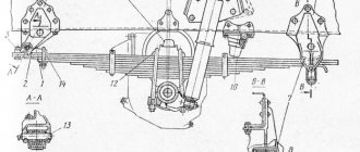
In the family of KAMAZ vehicles, many different drive axles are used, which have both significant and non-significant design differences. All drive axles for KAMAZ can be reduced to the five types shown in the figure.
The drive axles of all-wheel drive and non-all-wheel drive vehicles differ in the design of the crankcases and final drives. The designs of various models of drive axles of all-wheel drive vehicles are largely identical and differ in the presence of a cross-axle differential locking mechanism (IDL), main gears, hubs and brake elements. The front drive axles of all-wheel drive vehicles differ from the intermediate and rear axles in the design of the housings, main gears, and the presence of rotating mechanism elements. The design of various modifications of the front drive axles of all-wheel drive vehicles is largely identical and differs in the main gears and elements of the braking mechanism.
The main differences between different models of non-all-wheel drive axles: disc or hub wheel mounting; reinforced crankcase beam (sheet 14 mm); presence or absence of ICD, reinforced axle shafts; various elements of brake mechanisms for different brake chambers; various main gears with different gear ratios (7.22; 6.53; 5.94; 5.43); and other minor design differences.
Some of the most commonly used drive axles and their main design differences are presented in Table 31.
- Repair of KamAZ drive axles
- Replacement of KamAZ axles
Rice. 180. Axles of the vehicle family for KAMAZ
Table 31.
| Bridge | Carter | main gear | Hub | Brake mechanism | Brake chambers | Fist |
| Axles of all-wheel drive vehicles xxx-23xxxxxxxxx front | ||||||
| 4310-2300010 | 4310-2301010 | 4310-2302010 | 4310-3103011 | As part of bridges | 100-3519210 | 4310-23004062 4310-23004064 4310-23004065 |
| 43114-2300012 | 43114-2302010 | 4310-3103009 | ||||
| 4326-2300010 | 4326-2302010 | 4310-3103011 | 100-3519210 | |||
| Axles of all-wheel drive vehicles ххх-25ххххххх middle and ххх-24ххххххх rear | ||||||
| 4310-2400010 | 4310-2501010 | 4310-2402010 | 4310-3103011 | 4310-3502010 | 100-3519210 | 4310-2403070 4310-2403071 |
| 4310-2500010 | 4310-2502010 | |||||
| 43114-2500010 | 43114-2501007 with ICD | 55112-2502011 | 4310-3103009 | |||
| 43114-2400012 | 43114-2402011 | |||||
| Axles of four-wheel drive vehicles xxx-25ххххххх middle and ххх-24ххххххх rear | ||||||
| 53229-2500021 | 53229-2501007 with ICD | 53229-2502011 | 65115-3104010 | 53229-3502010 | 100-3519100 | 53229-2403070 53229-2403069 |
| 53229-2400021 | 53229-2401007 with ICD | 53229-2502011 | ||||
| 53215-2400010 | 5320-2401010 | 53215-2402011 various gear options | 53205-3104010 | 5511-3502010 | 53205-2403070 53205-2403069 | |
| 53215-2500010 | 5320-2501010 | 53215-2502011 various gear options | ||||
On KamAZ vehicles with a 6x4 wheel arrangement, two drive axles are installed - intermediate and rear. The design of the bridges is similar. The difference lies in the installation of a locked center differential and individual original parts mating with it in the main gear of the intermediate axle.
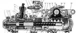
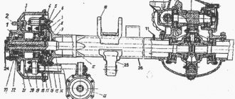
In Fig. 181 shows a cross section of the rear and intermediate drive axles. Each KamAZ drive axle consists of an axle housing, main gear, differential and axle shafts.
Rice. 181. Rear axle: 1 — spacer ring; 2 — brake drum; 3 — shield; 4 — safety valve; 5 — main gear housing; 6 — hairpin; 7 — crankcase gasket; 8 — right axle shaft; 9 — rear axle housing; 10 — control plug; 11 — magnetic drain plug; 12 — left axle shaft; 13 — spring support; 14 — rocket rod bracket; 15 - bolt; 16 — brake chamber with spring energy accumulator; 17 — brake mechanism; 18 — cuff; 19, 20 — tapered roller bearings; 21 — bearing fastening nut; 22 — axle shaft gasket; 23 — lock washer of the lock nut; 24 - lock nut; 25 — axle shaft mounting stud; 26 - nut; 27 — spring washer; 28 — expansion sleeve; 29 — hub; 30 - wheel clamping The bridge consists of an axle housing, main gear, differential and axle shafts.
The intermediate and rear axle housings are welded, made of stamped steel beams, to which are welded flanges for attaching the main gear housings and brake calipers, wheel hub axles, reaction rod mounting brackets and spring supports. On the axle housings of dump trucks, mounting plates are welded for fastening the spring supports.
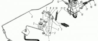
On KamAZ-53229 and KamAZ-65115 vehicles, the installation of drive axles (Fig. 182) with a cross-axle differential locking mechanism is provided, while the main gear differs in that the left cup of the cross-axle differential is made with splines for installing its locking clutch (see Fig. 183 ).
Rice. 182. Drive axle : 1 - brake chamber with spring energy accumulator; 2 — brake drum; 3 - hub; 4 — bearing nut; 5 — rear brake; 6 — left axle shaft; 7 — axle housing; 8 - safety valve; 9 — transmission of the main bridge; 10 — axle shaft right
Rice. 183. Main gear of the drive axle (fragment)
The bridge beams are strengthened by increasing the thickness of the walls.
The axle shafts have been strengthened due to a change in steel grade and an increase in the number of splines from 16 to 20.
The cross-axle differential locking mechanism is installed in the housing of the rear and middle axles. To ensure remote activation of the locking mechanism in the cockpit, there is a button with the corresponding symbol on the instrument panel. When the key is pressed, the electric pneumatic valve circuit closes and air enters the diaphragm chamber. The piston, moving the locking fork, connects the axle shaft coupling with the differential cup coupling. When the lock is activated in the cockpit, the warning lights on the instrument panel light up.
When carrying out maintenance (service C), to check the operation of the inter-axle differential locking mechanism, first turn on the inter-axle lock, and then press the inter-axle lock enable button, and the two indicator lamps for turning on the inter-axle locking of the drive axles should light up.
Engaging the lock is only permitted in slippery, muddy road conditions.
The lock should be engaged immediately before a slippery section of the road. When one of the wheels slips, the lock cannot be engaged. In this case, it is necessary to disengage the clutch and engage the lock after stopping the car. Switching the lock on and off should be done with the clutch pedal depressed.
When driving onto a hard, dry road, the lock must be turned off. Driving with the lock engaged will cause parts to break.
The main transmission of the bridges is two-stage. The first stage consists of a pair of bevel gears with spiral teeth, the second stage - of a pair of cylindrical helical gears.
For flat operating conditions of road trains, the recommended gear ratio is 5.94; for mountain conditions - 7.22; for rough terrain - 6.53. Changing the gear ratio of the main gear is achieved by installing gears with different combinations of teeth in a cylindrical pair (see Table 32).
Table 32. Main gear ratio depending on the number of gear teeth in a cylindrical pair
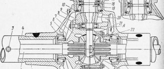
The main gear of the driving front axle (Fig. 184), unlike the main gears of the intermediate and rear axles, is attached to the axle housing with flanges located in a vertical plane. Original parts of the main drive (Fig. 185) of the front axle: cup 3 of the wheel differential, housing 31 of the main gear, input shaft 11, cover 17, bearing 8. The remaining parts and assembly units are unified with the parts and assembly units of the main drive of the rear axle.
Rice. 184. Front drive axle : I — front brake block; 2 — pad roller; 3 — expanding left fist; 4 - screw-in fitting; 5 — adapter fitting; 6 — air supply head; 7 — left steering knuckle housing; 8—oiler; 9—steering knuckle lever; 10—main gear of the front axle; 11 — adjustment lever; 12— ball joint of the steering knuckle; 13 — inner left fist of the hinge; 14 - plug; 15 — joint knuckle liner; 16 — hinge disk; 17 - cuff; 18 — lower lining of the fist; 19, 24, 34 — bearings; 20 — cuff padding; 21 — brake flap; 22 — front brake caliper; 23 — brake pad axis; 25 — left steering knuckle axle; 26 — hub with brake drum; 27, 32—lock washers; 28—drive flange; 29 — air shut-off valve; 30 — outer joint knuckle; 31 — bearing lock nut; 33 - bearing nut
The front axle housing is cast as one piece with the left short axle housing. The right casing is pressed into the axle housing. Ball joints with welded pins are attached to the flanges of the axle housings on studs. Bronze bushings are pressed into the ball joints, in which the internal cams of the constant velocity joints are installed.
The steering knuckle housings are located on the kingpins, which rotate on tapered roller bearings. Trunnions and brake calipers are attached to the steering knuckle housings with studs. Bronze bushings are pressed into the trunnions, in which the outer knuckles of the hinges rotate.
Torque from the inner knuckle to the outer knuckle is transmitted through a constant velocity joint. At the splined end of the outer knuckle there is a drive flange, which is attached to the hub with studs.
Rice. 185. Main gear of the front axle: 1 — bearing cover; 2 — driven cylindrical gear; 3 — differential cup; 4 — support washer of the semi-axial gear; 5, 13, 14, 24, 25 — tapered roller bearings; 6 — semi-axial gear; 7 — satellite support washer; 8, 22 — cylindrical roller bearings; 9 - key; 10 - plug; 11 - input shaft; 12 — driving bevel gear; 15 — cuff; 16 - flange; 17′, 27 — covers; 18, 26 — bearing cups; 19, 30 — adjusting washers; 20 — spacer sleeve; 21 — driven bevel gear; 23 — driving cylindrical gear; 28 — support washer; 29 - nut; 31 — main gear housing; 32 — differential crosspiece; 33 — satellite; 34 — adjusting nut; 35 — nut stopper; E - adjustable size
Gearbox diagram KamAZ 5320 4310 6520 65115
Gearbox diagram KamAZ 5320 4310 6520 65115 is a mechanism designed to transmit the rotation of the crankshaft to the wheels. It causes the truck axles to rotate and experiences enormous loads.
The unit consists of a main gear and a differential. They are placed in a crankcase, which is mounted on special flanges in the central part of the bridge. The normal functioning of the unit and the interaction of parts is ensured by lubrication. The crankcase is filled with oil through the filler hole, and its level is monitored through the control hole in the crankcase cover. Grooves on the inner surface of the crankcase and channels in its walls serve to supply oil to the bearings.
Device
Moscow designers also took part in the creation of the KamAZ car. At the time of the creation of the car, an advanced principle for the interaction of drive axles was developed and implemented. This refers to a permanent drive, which has four cardan shafts.
At the same time, the transmission is equipped with a center differential, which is supported by electric and pneumatic locking. There are several modifications that have some differences, but they are not significant. The KAMAZ 4310, 43118 vehicle is equipped with a KAMAZ-740.10 engine, which has a power of 210 -220 hp.
The basic version of the KamAZ 4310 vehicle is characterized by a shorter platform with a voluminous awning and a tailgate that folds down. The body has a row of seats for 30 people, which can be transformed, that is, they are folding. Years of production: 1983-1990.
KamAZ-43118 has an enlarged platform, which has a significantly higher load capacity. This modification of the KamAZ car began to be produced in 1996.
One of the important parts of the car is the gearbox, namely the KamAZ transfer case; it disperses torque if the road is bad, and it is distributed between the axle of the front of the car and the rear of the truck. What is the purpose of the transfer case?
How does a transfer case work?
Kamaz 4310 transfer case diagram
After turning on the switch, compressed air is not able to enter the pneumatic chambers, and therefore the diaphragms return to their original position. The torque between the shaft gears is transferred to the races and satellites. The gears, carried by the satellites, allow you to move along a good, damage-free road as a single unit. If the road becomes uneven, for example, off-road, the front axle and the bogie move differently, and then the epicycle with the sun gear rotates at different speeds, and the satellites rotate not only around the main axis, but also around their own axes.
Both gears can turn on at the same time, and to prevent this, a lock is supposed to prevent this from happening. If we take into account the differential lock, then when locked, the pneumatic chamber moves the clutch, which serves as a connecting element between the cage and the drive shaft on the front axle. This allows you to move on roads of different quality, both good and poor quality, as a single mechanism, the torque is proportionally distributed between the front axle and the bogie, as are the loads on them.
To eliminate the load on the transmission, the differential is constantly active, that is, unlocked. Only in a situation where you are driving on slippery roads should you use a lock, as this reduces the risk of wheel slipping and guarantees the safe movement of the vehicle.
Lubricating the RK is quite simple. It is enough to spray the oil, and about five liters of oil of a certain brand are poured into the crankcase.
Warning light circuit diagram
This system controls the rear brakes and turn signals. It serves to notify other road users about the maneuvers the truck is making. The general diagram of this system is shown in the figure below:
The numbers on the diagram indicate:
- left lamp;
- right lamp;
- turn signal and hazard warning relay;
- fuse PR 119 (6 A);
- light switch;
- fuse 13.3722 (7.5 A);
- fuse PR 310 (10 A);
- hazard warning light switch;
- turn signal right
- left turn indicator;
- rear left lamp
- rear right lamp;
- brake light switch;
- trailer solenoid valve switch;
- brake signal relay;
- sound signal (buzzer);
- 18, 19 — switches for pressure drop alarms in the brake air drive receivers;
- parking brake warning switch;
- relay-interrupter for the parking brake system activation indicator;
- reverse light switch;
- reversing light;
- trailer socket 24 V;
- center differential lock warning switch;
- 27, 28 — signaling units;
- oil filter clogged warning switch;
Advantages and disadvantages
- Powerful appearance;
- Excellent maneuverability;
- High ground clearance;
- All-wheel drive system;
- Ability to change tire pressure remotely;
- The machine is not so difficult to repair and operate;
- Easily find required parts and spare parts;
- Able to work at different temperature conditions;
- Relatively low cost of the machine;
- There are many different modifications for this car;
- There is a sleeping place;
- Not afraid of fords, the depth of which can reach 1.5 meters;
- A winch can be installed as a separate option.
- High diesel fuel consumption;
- Outdated cabin appearance;
- Old truck interior in need of improvement;
- Low load capacity;
- There is no air suspension for the driver's seat;
- Outdated dashboard;
- Inconvenient location of the accelerator pedal;
- Uncomfortable steering wheel.