Designations on electrical diagrams (wiring diagrams) 4 VEHICLE INFORMATION SYSTEM Maintenance system (WS) (diagrams 1-3) 12 WORKING MIXTURE PREPARATION SYSTEM Engine management system (MR) (сx. 4.5) 17 ENGINE ELECTRICAL EQUIPMENT Starter (diagrams 6.7 ) 21 Generator (dg. 8.9) 23 Pre-heating system (dg. 10.11) 25 MOTION CONTROL SYSTEM Tempomat (dg. 12-15) 26 Traffic control system (FR) (dg. 16-18) 30 FUEL SYSTEM Fuel pre-filter with heated water separator (Fig. 19) 38 MECHANICAL TRANSMISSION Gear shift assist system (Fig. 20) 39 Electro-pneumatic gear shift (EPS) (Fig. 21) 40 Electronic drive control system (EAS) (Fig. 22, 23). 30) 54 REAR AXLE Rear axle differential lock activation system (Fig. - PNEUMATICS Parking brake system (diagram 39,40) 77 CHASSIS Power supply, batteries (diagram 41,42) 78 Voltage converter system (diagram 43,44) 83 BASIC MODULES Electrical diagram of the base module (diagram 45-50) 85 Special module with the possibility of parameterization (PSM) (diagrams 51-55) 103 Places of intersection of communications (KAM) (diagrams 56,57) 117 Instrument panel (INS) (diagrams 58-62) 118 CAB ATTACHMENTS Heated windshield (diagram 63) 130 Ceiling curtains (diagram 64) 130 Sunshade (internal) (diagram 65-67) 131 Window regulator (diagram 68) 132 Sliding sunroof (SHD) (diagram 69) 133 Central locking (diagram 63) ZV) (diagram 70,71) 134 Remote locking control (diagram 72,73) 136 Comfort locking system (diagram 74) 137 Remote locking control (diagram 75) 139 Alarm and security system (EDW) (diagram 75) 76.77) 141 Refrigerator (diagram 78) 145 Rear view mirror (diagram 79) 145 CAB ELECTRICAL EQUIPMENT External lighting (diagram 80-83) 146 Internal lighting (diagram 84-87) 154 Rotating light (diagram 88) 160 Sound signal, pneumatic signal (diagram 89,90) 160 HEATING CONTROL SYSTEM Heating (diagram 91-94) 162 Air conditioner (diagram 95-97) 171 Autonomous heating system (ZHE) (diagram 98-101) 176
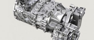
Features of gearbox control on the Mercedes-Benz Actros
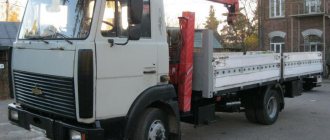
Mercedes-Benz Actros
Automatic transmission simplifies starting from a standstill, and also allows you to independently set the required rhythm of movement while moving; it can change through one or several gears. The automatic transmission complies with Euro-5 standard.
As a selector in the cabin there is a joystick with a button for turning on the speed and neutral gear. With its help, you can engage first from reverse gear. As a rule, neutral gear is activated when stopped at a traffic light.
Mercedes-Benz Actros, automatic transmission appearance
The Mercedes Actros gearbox can operate in manual or automatic mode, which can be switched to by pressing the M/A button. The display informs the motorist about the mode in which the vehicle is moving. EA – automatic, M – mechanical control. The driver will be provided with excellent driving comfort.
Shifting gears in manual driving mode is done using a “tongue” under the main joystick. To change to the top gear, the “tongue” should be pressed up, and to move to the bottom gear down. If you need to jump into two gears at once, you need to press the upper shift button (speed switching on) and move the joystick forward.
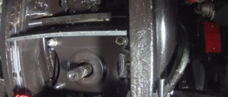
As a rule, the speed change occurs when it reaches 1200 rpm. This is the maximum rate of power transfer from the engine to the wheels. This box needs diagnostics when oil traces are detected, if there is unclear gear shifting, or a crunching sound when changing gears.
INSTRUCTIONS FOR REPAIR AND OPERATION OF SPECIAL TRUCKS.
Pages
Most Viewed
(Mercedes Benz Actros) gearboxes Gearbox 715.510 /520 /561 in TYPE 375.4, 944 Gearbox 715.320 /510 in TYPE 952.6, 953.6 Gearbox 715.060 /320 /510 in TYPE 950.5 /6, 952.5, 954.5
The diagrams contain the following components of the Electrical circuit of electro-pneumatic gear shifting (EPS)
Joystick connection point Electrical emergency switch Protection meter Voltage supply Stroke sensor ASIC Interchangeable depending on version Individual valves in the Telma retarder With power take-off 2 (NMV) and viscous coupling WSK: chamber 1=3, chamber 3=1 Only for all driving wheels Cab-chassis plug-in connection Rear axle cross-lock solenoid valve GS/EPS valve block MS2 solenoid valve GS/EPS valve block MS1 solenoid valve GS/EPS valve block MR2 solenoid valve GS/EPS valve block MR1 GS/EPS valve block solenoid valve MG2 Valve block GS/EPS solenoid valve MG1 Valve block GS/EPS solenoid valve MUB Valve block GS/EPS solenoid valve MGB Valve block GS/EPS solenoid valve MUE Valve block GS/EPS solenoid valve MGE Off-road transmission solenoid valve Center locking solenoid valve Central vehicle CAN bus switching point on the front of the cab Central vehicle CAN bus switching point on the front of the cab, optional Automatic mode switch Speed detection and direction of rotation recognition Only in the EAS system or for all-wheel drive vehicles with a two-way transfer case Basic module GS/EPS joystick GS/EPS control unit Clutch travel sensor Intermediate shaft speed sensor Rotation speed sensor Gear engagement sensor Track activation sensor Divider activation sensor Range activation sensor GS/EPS/tipping pump fuse, cl. 30 (fuse block A1) Fuse GS/EPS/EAS, cl. 15 (basic module) Modular tachograph Differential lock switch Transfer case switch Cab-chassis plug connection
Electronic Drive System (EAS) Wiring Diagram
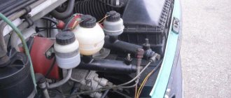
Gearbox 715.500 /520 /540 in TYPE 950, 952, 954 until 12/31/99 with CODE (GE1) Electronic drive control in conjunction with GS/EPS, KS/MKR, AG/AGE, KB/EMK Gearbox 715.500 /520 in TYPE 953 until 12/31/99 release with CODE (GE1) Electronic drive control in conjunction with GS/EPS, KS/MKR, AG/AGE, KB/EMK gearboxes 715.500 /520 /540 in TYPE 950, 952, 954 from 1.1.00 to 30.4. 01 release with CODE (GE1) Electronic drive control in conjunction with GS/EPS, KS/MKR, AG/AGE, KB/EMK gearbox 715.500 /520 in TYPE 953 from 1.1.00 to 30.4.01 release with CODE (GE1) Electronic control drive together with GS/EPS, KS/MKR, AG/AGE, KB/EMK gearbox 715.500 /520 /540 in TYPE 950, 952, 954 after 1.5.01 release with CODE (GE1) Electronic drive control together with GS/EPS, KS/MKR, AG/AGE, KB/EMK gearbox 715.500 /520 in TYPE 953 after 1.5.01 release with CODE (GE1) Electronic drive control in conjunction with GS/EPS, KS/MKR, AG/AGE, KB/EMK gearbox 715.510 in TYPE 950, 954 after 1.5.01 release with CODE (GE1) Electronic drive control in conjunction with GS/EPS, KS/MKR, AG/AGE, KB/EMK
How to blow out a box on a Mercedes Actros?
Why is it necessary to blow out the box? This procedure is important to perform if the Mercedes Actros gearbox has been repaired. In particular, individual transmission mechanisms were replaced, for example, the clutch and master cylinder were changed. Blowing can be in a small or large circle.
The algorithm for purging in a small circle is as follows:
If you need to blow in a large circle, then you need to hold down two side buttons on the joystick. The procedure is not complicated; each driver can carry it out independently.
Discounts from the help desk
When you mention ACC you can get discounts on parts and services
Automotive Help Desk: auto news, spare parts in Krasnoyarsk for foreign and domestic cars, disassembled cars, car repairs, addresses and phone numbers of companies, bulletin boards, spare parts catalogues, service and repair manuals.
All information presented on the site is for informational purposes only and under no circumstances constitutes a public offer.
INTRODUCTION 3 1. OPERATING MANUAL FOR MERCEDES-BENZ ACTROS 4 2. MAINTENANCE OF MERCEDES-BENZ ACTROS 28 1. Replacing the oil filter and engine oil 28 2. Replacing the oil separator 28 3. Adjusting the valve clearance 28 3.1. Adjusting the valve clearance 28 3.2. Adjusting the valve bridge 29 4. Fuel pre-filter with water separator 30 5. Replacing the fuel filter 30 6. Checking brake lining wear on the maintenance system display 30 7. Lubrication points 31 8. Replacing the air filter element 32 9. Changing the oil in the manual transmission 33 10. Replacing the power take-off filter 33 11. Changing the oil in the retarder 33 12. Changing the oil in the front axle gearbox 730.1 34 13. Changing the oil in the rear axle gearbox 748.2 34 14. Changing the oil in the rear axle gearbox 748.59 35 15. Checking and adjusting coolant level 35 16. Checking and adjusting the fluid level in the clutch hydraulic reservoir 35 17. Replacing the granular air dryer cartridge 35 18. Checking and adjusting the headlight beam angle 36 19. Fault memory (list of fault codes) of the WS (FSS) maintenance system 37 3. DIESEL ENGINES OM 501 V6 12.0 l and OM 502 V8 16.0 l 39 1. Checking the cylinders using a probe 39 2. Checking the compression 39 3. Removing and installing the engine 40 4. Removing and installing the cylinder head cover 41 5. Removing and installing installing the cylinder head 41 6. Measuring the cylinder diameter 42 7. Measuring the liner protrusion 42 8. Front crankshaft oil seal 43 9. Timing housing cover 43 10. Engine sump 44 11. Constant throttle 44 12. Timing housing 45 13. Checking and replacing connecting rod 45 14. Pistons 46 15. Piston rings 47 16. Crankshaft dimensions 47 17. Pulley/vibration damper removal and installation 48 18. Camshaft 49 19. Lapping valve seat rings 49 20. Valve guides 51 21. Lapping valves 52 22. Removal and installation of the poly V-belt 52 23. Removal and installation of the compressed air distribution manifold 53 24. Removal and installation of the turbocharger 53 25. Removal and installation of the exhaust manifold 54 26. Exhaust gas pressure chamber 54 27. Engine brake flap 55 28. Removal and installation of the cooling system pump 56 29. Removal and installation of thermostats 58 30. Removal and installation of the cooling system radiator 58 31. Coolant level sensor 59 32. Radiator fan 59 33. Removal and installation of the oil pump 59 34. Disassembly and assembly of the oil pump 60 35. Removing and installing the bypass valve 60 36. Removing and installing the oil filter housing 61 37. Removing and installing the oil cooler 61 38. Removing and installing the fuel filter 62 39. Removing and installing the fuel priming pump/power steering pump 62 40. Removing and installation of a fuel heater 63 41. Removal and installation of a starter 63 42. Removal and installation of a generator 64 43. Diagnostics of an electric flare air heater (FLA) 64 Fuel injection system 65 44. Removal and installation of an injector 65 45. Location of components of the MR engine management system 66 46. Removing and installing high pressure fuel lines 67 47. Removing and installing the high pressure pump 67 48. Removing, installing and adjusting the crankshaft angle sensor bracket 68 49. Removing and installing the fuel injection control unit 68 50. Troubleshooting the MR (PLD) system 69 51 Fault memory (list of fault codes) of the MR engine management system (PLD) 69 52. Troubleshooting of the MR engine management system (PLD) 74 53. Tightening torques 75 4. TRANSMISSION 76 Clutch and torque converter 76 1. Removing and installing the clutch 76 2 Removing and installing the clutch release lever 76 3. Removing and installing the clutch safety valve 77 4. Removing and installing the clutch master cylinder 77 5. Removing and installing the clutch hydraulic master cylinder 77 6. Removing and installing the clutch hydraulic booster 78 7. Removing and installing torque converter (GTR) 78 8. Removing and installing the torque converter from the gearbox 78 9. Removing and installing the GTR control unit 79 10. Removing and installing the inductive pulse generator GTR 80 11. Dismantling and assembling the oil filter on the GTR 80 12. Oil injection flange 80 13 Oil pump for GTR 81 14. Retarder control valve 81 15. Clutch booster for electronic transmission control system 81 16. Clutch booster sensor for electronic transmission control system 82 Manual transmissions 715.500/510/520/540 82 17. Removal and installation of manual transmission 82 18. Removing and installing the range shift cylinder 83 19. Removing and installing the gear shift cylinder 84 20. Dismantling and assembling the range shift cylinder 84 21. Dismantling and assembling the gear shift cylinder 85 22. Reversing light switch 85 23. Neutral gear sensor 85 24. Vehicle speed sensor 85 25. Oil temperature sensor 85 26. Multiplier 85 27. Removing and installing the gearbox output flange 88 28. Dismantling and assembling the secondary shaft 88 29. Determining the thickness of the gasket for the secondary shaft 90 30. Primary shaft 91 31. Checking wear between the cone ring and the synchronizer clutch 91 32. Intermediate shaft 92 33. Hydraulic shift cylinder (715.500/510/520/540 gearboxes with code GS3 “Hydraulic gear shift”) 92 34. Gearshift mechanism (715.500/ gearboxes) 510/520/540 with code GS1 "Mechanical shifting") 92 35. Forks and shift rods (gearboxes 715.520/540 with code GS1 "Mechanical shifting" and code GS3 "Hydraulic shifting") 93 36. Forks and shift rods (715.500/510 transmissions with GS1 code "Mechanical Shift" and GS3 code "Hydraulic Shift" and 715.500/510/520/540 transmissions with GS2 code "Shift Control System") 93 37. Shift lever gears (gearboxes 715.500/510/520/540 with code GS3 “Hydraulic gear shift”) 93 38. Tightening torques 94 5. SUSPENSION 95 Front suspension 95 95 1. Removal and installation of spring 95 2. Shock absorber 95 3. Anti-roll bar 96 Front axle 739.5 96 4. Removing and installing the front axle 96 4.1. Removing and installing the front axle (vehicles with codes AN8 and AN9 “Hydraulic steering”) 96 4.2. Removing and installing the front axle (vehicles without codes AN8 and AN9 “Hydraulic steering”) 96 5. Hub (front axle with drum brakes) 97 6. Hub (front axle with disc brakes) 98 7. Removing and installing the steering knuckle 98 7.1. Front axles with drum brakes 98 7.2. Front axles with disc brakes 99 8. Adjusting the axial clearance of the steering knuckle 99 Front axle 730.1 (all-wheel drive vehicles) 99 9. Removing and installing the front axle 99 10. Checking the wheel hub runout 100 11. Hub 100 12. Steering knuckle 101 13. Flange front axle gearbox 101 14. Front axle gearbox 102 15. Ring gear with differential 102 Rear suspension 103 16. Removal and installation of spring 103 17. Shock absorber 103 18. Anti-roll bar 104 19. Pneumatic springs 104 Rear axle 748.2 104 20. Removal and installation rear axle (rear axle 748.21 without intermediate drive and with air suspension) 104 21. Hub 105 22. Removal and installation of ring gear and rear axle reduction gears (rear axle with intermediate drive) 106 23. Removal and installation of ring gear and rear axle reduction gears (rear axle without intermediate drive) 106 24. Removal and installation of ring gear with differential 107 25. Disassembly and assembly of differential 107 26. Disassembly and assembly of rear axle drive gear (without intermediate drive) 108 27. Removal and installation of intermediate drive drive shaft 109 28. Removing and installing differential lock (center lock) 109 29. Differential lock control cylinder (without intermediate drive) 110 Rear axle 748.59 110 30. Removing and installing rear axle 110 31. Hub 111 32. Rear axle drive gear oil seal 111 33 Rear axle gearbox 112 34. Mechanical differential lock 112 35. Tightening torques 113 6. MERCEDES ACTROS STEERING 114 1. General information 114 1.1. Single-channel steering 114 1.2. Two-channel steering 116 2. Removing and installing the contact coil 118 3. Lower steering shaft 118 - 4. Steering column bracket 119 5. Steering wheel 119 6. Checking and adjusting the middle position of the steering mechanism 120 7. Removing and installing the steering mechanism 120 7.1. Steering gear 765.889 (LS on models 950, 952, 953, 954 120 7.2. Steering gear 765.82 on models 950.0/1/2, 952.0/1/2, 953.1, 954.0/1/2 121 8. Power steering pump/fuel booster pump 122 9. Tightening torques 122 7. BRAKE SYSTEMS 123 Service brake system 123 1. Mechanical brake light switch (950.0/1/2/3, 952.0/1/2/3, 953.1/3, 954.0/1/2 except code 8B8 "Electro-pneumatic brake (EPB) 123 2. Removal and installation of brake pads 124 2.1. Models 950, 952, 953, 954 with disc brakes SB 7000, SN 7000 124 2.2. Models 950, "952, 953, 954 with front axle 739.54 124 2.3 Models 950, 952, 953, 954 with rear axle 748.2 124 3. Brake support 125 3.1 Models 950, 952, 953, 954 with rear axle 748.21 with disc brakes, with rear axle 748.2 2 with disk brake mechanisms, with rear axle 748.590 with disc brakes, with rear axle 749.011 with disc brakes, with rear axle 749.108 with disc brakes 125 3.2. Models 950, 952, 953, 954 with front axle 739.54 125 3.3. Models 950, 952, 953, 954 with rear axle 748.2 with disc brakes 125 4. Brake caliper 126 4.1. Models 950, 952, 953, 954 with disc brakes 126 4.2. Models 950, 952, 953, 954 with rear axle 748.23 126 5. Diaphragm brake cylinder 126 6. Brake drum (models 950, 952, 953, 954 with front axles 739.541 and 730.1, rear axles 748.23 and 748.24 ) 128 7. Brake disc (models 950, 952, 953, 954 with rear axles 748.21, 749.732/733 and 748.22) 128 8. Condensation sensor 128 9. Brake pad wear sensor (models 950, 952, 953, 954 with front axles 739.541 and 73 0.1, rear axles 748.23 and 748.24 with Haldex clearance adjuster) 129 10. Cam shaft with support bracket 129 11. Valve for service brake system 130 12. Valve for parking brake system 130 Retarder Telma Focal F 3300 130 13. Removal and installation of retarder Telma Focal F 3300 13 0 14. Telma 131 retarder stator support Voith R115 retarder 131 15. Removing and installing Voith R115 retarder 131 16. Proportioning valve 131 17. Oil temperature sensor 132 18. Oil reservoir 132 19. Retarder heat exchanger 132 20. Retarder coolant temperature sensor 133 4 channel anti-lock braking system ABS 133 21. ABS fault codes 133 22. Tightening torques 134 8. VEHICLE ELECTRICAL EQUIPMENT 135 1. Removing and installing headlights (models 950.5/6, 952.5/6, 953.6, 954.5 with cab 940.899, models 95 0.0/1/2 /3, 952.0/1/2/3, 953.1/3. 954.0/1/2 with cab 942.899) 135 2. Removing and installing rear light 135 3. External lighting switch 136 4. Voltage converter 136 5. Main power switch (models 950.0/1/2/3, 952.0/1/2/ 3, 953.1/3, 954.0/1/2) 136 6. Emergency switch on the frame 136 7. Windshield washer reservoir 137 8. Windshield wiper motor 137 heating system and air conditioning 137 9. Air conditioning elements 137 10. Removing and installing the heater radiator 138 11. Removing and installing the heater 137 12. Electromagnetic clutch of the air conditioning compressor 139 9. MERCEDES ACTROS 140 BODY 1. Removing and installing the cab (body 942.899) 140 2. Cab suspension air springs (cab 942.899 with code FL2 “Cab air suspension”) 141 3. Stabilizer cabin 141 4. Cab lift cylinder 142 5. Cab support spring strut 142 6. Removing and installing the central part of the instrument panel 143 7. Instrument panel top cover 143 8. Footwell cover 143 9. Door lock (models 950.0/1/ 2/3, 952.0/1/2/3, 953.1/3, 954.0/1/2) 144 10. External door opening handle 144 11. Removing and installing the door 144 12. Window lifters (models 950.0/1/2/3, 952.0/1/2/3, 953.1/3, 954.0/1/2) 145 13. Rear view mirror 145 14. Removal and installation of the front bumper 146 15. Tightening torques 146 ELECTRICAL CONNECTION DIAGRAMS (WIRING DIAGRAMS) MERCEDES-BENZ ACTROS 147