- home
- Engine
- …
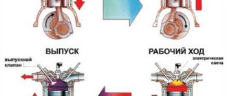
The efficiency of an internal combustion engine often depends on the gas exchange process, that is, filling the air-fuel mixture and removing exhaust gases. As we already know, this is done by the timing mechanism (gas distribution mechanism), if you correctly and “finely” adjust it to certain speeds, you can achieve very good results in efficiency. Engineers have been struggling with this problem for a long time; it can be solved in various ways - for example, by influencing the valves themselves or by turning the camshafts...
To ensure that internal combustion engine valves always worked correctly and were not subject to wear, at first simply “pushers” appeared, then hydraulic compensators , but this turned out to be not enough, so manufacturers began introducing so-called “phase shifters” on camshafts.
Why do we need phase shifters at all?
To understand what phase shifters are and why they are needed, first read the useful information below. The thing is that the engine does not work the same at different speeds. For idle and low speeds, “narrow phases” will be ideal, and for high speeds, “wide” phases will be ideal.
Narrow phases - if the crankshaft rotates “slowly” (idling), then the volume and speed of exhaust gas removal are also small. It is here that it is ideal to use “narrow phases”, as well as minimal “overlap” (the time of simultaneous opening of the intake and exhaust valves) - the new mixture is not pushed into the exhaust manifold, through the open exhaust valve, but accordingly, exhaust gases (almost) do not pass into the intake . This is the perfect combination. If you make the “phasing” wider, precisely at low crankshaft rotations, then the “working off” can mix with the incoming new gases, thereby reducing its quality indicators, which will definitely reduce power (the engine will become unstable or even stall).
Wide phases - when the speed increases, the volume and speed of the pumped gases increases accordingly. Here it is already important to blow through the cylinders faster (from exhaust) and to drive the incoming mixture into them faster; the phases should be “wide”.
Of course, the discoveries are driven by the usual camshaft, namely its “cams” (a kind of eccentrics), it has two ends - one is sharp, it rises, the other is simply made in a semicircle. If the end is sharp, then maximum opening occurs, if it is rounded (on the other side), then maximum closing occurs.
BUT standard camshafts DO NOT have phase adjustment, that is, they cannot widen them or make them narrower; nevertheless, engineers set average indicators - something between power and efficiency. If the shafts are tilted to one side, the efficiency or economy of the engine will decrease. “Narrow” phases will not allow the internal combustion engine to develop maximum power, but “wide” ones will not work normally at low speeds.
I wish I could regulate it depending on the speed! This is what was invented - in essence, this is a phase control system, SIMPLY - PHASE Shifters.
Causes of phase regulator malfunction
Malfunctions are divided directly into the phase regulator and its control valve. So, the reasons for the malfunction of the phase regulator are:
- Wear of the turning mechanism (blade/vane) . Under normal conditions, this happens for natural reasons, and it is recommended to change the phase regulators every 100...200 thousand kilometers. Contaminated or low-quality oil can accelerate wear.
- Displacement or mismatch of the set values of the phase regulator rotation angles . This usually occurs due to the fact that the rotating mechanism of the phase regulator in its housing exceeds the permissible rotation angles due to metal wear.
But the reasons for VVT valve failure are different.
- Failure of the phase regulator valve seal . For Renault Megane 2 cars, the phase regulator valve is installed in a recess in the front of the engine, where there is a lot of dirt. Accordingly, if the oil seal loses its tightness, then dust and dirt from the outside mixes with the oil and enters the working cavity of the mechanism. The result is jamming of the valve and wear of the rotating mechanism of the regulator itself.
- Problems with the valve electrical circuit . This could be a break, contact damage, insulation damage, a short to the housing or to the power wire, a decrease or increase in resistance.
- Ingress of plastic shavings . On phase regulators, the blades are often made of plastic. As they wear out, they change their geometry and fall out of their seat. Together with the oil, they enter the valve, disintegrate and are crushed. This can lead to either incomplete valve stem travel or even complete jamming.
Also, the reasons for the failure of the phase regulator may lie in the malfunction of other related elements:
- Incorrect signals from DPKV and/or DPRV . This may be due to problems with these sensors, or to the fact that the phase regulator has worn out, which is why the camshaft or crankshaft is in a position beyond the permissible limits at a particular time. In this case, together with the phase regulator, you need to check the crankshaft position sensor and check the DPRV.
- Problems with the ECU . In rare cases, a software failure occurs in the electronic control unit and even with all the correct data, it begins to generate errors, including in relation to the phase regulator.
Principle of operation
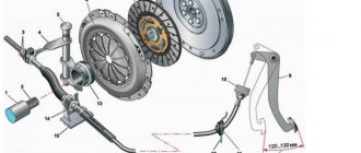
Now we won’t go into depth; our task is to understand how they work. Actually, a conventional camshaft has a timing gear at the end, which in turn is connected to a timing belt or chain .
The camshaft with a phase shifter at the end has a slightly different, modified design. Here there are two “hydro” or electrically controlled couplings, which on one side also engage with the timing drive (chain or belt), and on the other side with the shafts. Under the influence of hydraulics or electronics (there are special mechanisms), shifts can occur inside this clutch, so it can rotate slightly, thereby changing the opening or closing of the valves.
It should be noted that the phase shifter is not always installed on two camshafts at once; it happens that one is located on the intake or exhaust, and on the second there is just a regular gear.
As usual, the process is controlled by the ECU , which collects data from various engine sensors , such as crankshaft position, hall position, engine speed, speed, etc.
Now I suggest you consider the basic designs of such mechanisms (I think this will make your head clearer).
Subtleties of choice
When choosing a voltage phase control relay, you need to focus on the technical parameters of the device that is connected to the circuit.
For example, consider a situation when you need to select a model for connecting an ATS.
The algorithm of actions is as follows:
- WE DETERMINE THE CONNECTION METHOD - with or without “zero”.
- WE DETERMINE THE PARAMETERS. For an ATS circuit, it is important that the device monitors the fact of phase failure and the phase sequence. In this case, the delay time should be in the range between 10 and 15 seconds. Control of oscillations U greater or less than the set point is required. To switch a relay with the 0th wire, visual inspection is required for each phase.
After analyzing the requirements considered, preference can be given to EL11E.
In addition, when choosing, you need to take into account the modification of the relay. For example, domestically produced devices are designated as EL.
As for foreign products, their markings are somewhat different. For example, RANA B380 A A 3 C. Here “RANA” is the name of the series, B380 is the voltage 380V. The next two letters A are regulation using a potentiometer and the type of installation (for DIN rail). The number “3” indicates the case size of 3.5 cm, and C is the last digit of the marking.
VVT (Variable Valve Timing), KIA-Hyundai (CVVT), Toyota (VVT-i), Honda (VTC)
One of the first to propose turning the crankshaft (relative to the initial position) was Volkswagen, with its VVT system (many other manufacturers built their systems on its basis)
What does it include:
Phase shifters (hydraulic) are installed on the intake and exhaust shafts. They are connected to the engine lubrication system (it is actually the oil that is pumped into them).
If you disassemble the coupling, there is a special sprocket inside the outer casing, which is fixedly connected to the rotor shaft. The housing and rotor may move relative to each other when pumping oil.
The mechanism is fixed in the cylinder head, it has channels for supplying oil to both couplings, and the flows are controlled by two electro-hydraulic distributors. By the way, they are also attached to the block head housing.
In addition to these distributors, the system has many sensors - crankshaft frequency, engine load, coolant temperature, camshaft and crank position. When you need to turn or adjust the phases (for example, high or low speeds), the ECU, reading the data, gives orders to the distributors to supply oil to the clutches, they open and the oil pressure begins to pump the phase shifters (thus they turn in the right direction).
Idling - turning occurs in such a way that the “intake” camshaft ensures later opening and later closing of the valves, and the “exhaust” camshaft turns so that the valve closes much earlier before the piston approaches top dead center.
It turns out that the amount of spent mixture is reduced almost to a minimum, and it practically does not interfere with the intake stroke; this has a beneficial effect on the operation of the engine at idle speed, its stability and uniformity.
Medium and high speeds are where the task is to produce maximum power, so “turning” occurs in such a way as to delay the opening of the exhaust valves. Thus, the gas pressure remains on the power stroke. The intake valves, in turn, open after the piston reaches top dead center (TDC), and close after BDC. Thus, we seem to get a dynamic effect of “recharging” the engine cylinders, which brings with it an increase in power.
Maximum torque - as it becomes clear, we need to fill the cylinders as much as possible. To do this, you need to open the intake valves much earlier and, accordingly, close them much later, to save the mixture inside and prevent it from escaping back into the intake manifold. The “exhaust” valves, in turn, close with some advance before TDC in order to leave a slight pressure in the cylinder. I think this is understandable.
Thus, many similar systems now operate, the most common of which are Renault (VCP), BMW (VANOS/Double VANOS), KIA-Hyundai (CVVT), Toyota (VVT-i), Honda (VTC).
BUT these are not ideal, they can only shift the phases to one side or the other, but cannot really “narrow” or “expand” them. Therefore, more advanced systems are now beginning to appear.
Signs of a phase regulator malfunction
The complete or partial failure of the phase regulator can be judged by the following signs:
- Increased engine noise . Repeated clunking sounds will come from the camshaft mounting area. Some car enthusiasts say that they are similar to the operation of a diesel engine.
- Unstable engine operation in one of the modes . The engine can idle well, but accelerate poorly and lose power. Or vice versa, it’s normal to drive, but “choking” at idle. There is a general decrease in power output.
- Increased fuel consumption . Again, in some mode of engine operation. It is advisable to check fuel consumption over time using an on-board computer or diagnostic tool.
- Increased exhaust toxicity . Usually their number becomes larger, and they acquire a sharper fuel smell than before.
- Engine oil consumption increases . It may begin to actively burn out (its level in the crankcase decreases) or lose its performance properties.
- Unstable speed after starting the engine . This usually lasts about 2...10 seconds. At the same time, the crackling sound from the phase regulator is stronger, and then it subsides a little.
- Formation of a mismatch error between the crankshaft and camshaft or camshaft position . The code may differ for different machines. For example, at Renault, error code DF080 directly indicates problems with the “phasic”. Other machines often experience error p0011 or p0016, indicating system desynchronization.
The most convenient way to carry out diagnostics, decipher errors, and reset them is with a multi-brand auto scanner. One of these affordable options is Rokodil ScanX Pro
. They can take sensor readings for most cars since 1994. by pressing a couple of buttons. And also check the sensor’s response by turning on/off various functions.
Please note that in addition, when the phase regulator fails, only part of the indicated symptoms may appear or they may appear differently on different machines.
Honda (VTEC), Toyota (VVTL-i), Mitsubishi (MIVEC), Kia (CVVL)
To further regulate valve lift, even more advanced systems were created, but the ancestor was HONDA, with its VTEC ( Variable Valve Timing and Lift Electronic Control ) engine. The point is that in addition to changing the phases, this system can lift the valves more, thereby improving the filling of the cylinders or the removal of exhaust gases. HONDA is now using the third generation of such engines, which absorbed both VTC (phase shifters) and VTEC (valve lift) systems at once, and now it is called DOHC i- VTEC .
The system is even more complex, it has advanced camshafts with combined cams. Two regular ones on the edges, which press the rocker arms in normal mode, and a middle, more advanced cam (high profile), which turns on and presses the valves, say, after 5500 rpm. This design is available for every pair of valves and rocker arms.
How does VTEC work? Up to approximately 5500 rpm, the motor operates in normal mode, using only the VTC system (that is, it turns the phase shifters). The middle cam does not seem to be closed with the other two at the edges, it simply rotates empty. And when high speeds are reached, the ECU gives the order to turn on the VTEC system, oil begins to be pumped in and a special pin is pushed forward, this allows all three “cams” to be closed at once, the highest profile begins to work - now it is this that presses on the pair of valves for which it is designed group. Thus, the valve lowers much more, which makes it possible to additionally fill the cylinders with a new working mixture and remove a larger volume of “working off”.
It is worth noting that VTEC is on both the intake and exhaust shafts, this gives a real advantage and increase in power at high speeds. An increase of approximately 5 - 7%, this is a very good indicator.
It is worth noting that although HONDA was the first, similar systems are now used on many cars, for example Toyota (VVTL-i), Mitsubishi (MIVEC), Kia (CVVL). Sometimes, as for example in Kia G4NA engines, a valve lift is used on only one camshaft (here only on the intake).
BUT this design also has its drawbacks, and the most important is the stepwise activation of the work, that is, you go up to 5000 - 5500 and then you feel (the fifth point) the activation, sometimes like a push, that is, there is no smoothness, but I would like it!
Phase control relay EL-11E (380 V, 50 Hz), RKF, IEK
These phase control relay models are produced by, which has been on the market since 1992. The company is located in St. Petersburg.
The company's activities are based on the development and manufacture of industrial automation devices. During its existence, the company has managed to take a leading position in the manufacture of electronic devices on the Russian market. The number of goods produced exceeds 500 units.
The company's clients include such giants as Gazprom, Russian Railways, Aurora Concern, Lenenergo and others. The company's products are in high demand due to their quality and wide range of models.
Customers have at their disposal electronic time relays, voltage monitoring devices, maximum current relays, lighting control devices and much more.
Description and technical characteristics of relay EL-11E (380 Volt, 50 Hz)
The EL-11E relay has one normally closed, normally open and changeover contact.
The device is designed to control phases in a 3-phase network, operating at an alternating voltage of 380 Volts. In practice, it is used to control the presence of U and correct symmetry.
Soft start or Fiat (MultiAir), BMW (Valvetronic), Nissan (VVEL), Toyota (Valvematic)
If you want smoothness, please, and here the first company in development was (drum roll) – FIAT. Who would have thought, they were the first to create the MultiAir system, it is even more complex, but more accurate.
“Smooth operation” is applied here to the intake valves, and there is no camshaft at all. It is preserved only on the exhaust part, but it also has an effect on the intake (I’m probably confused, but I’ll try to explain).
Principle of operation. As I said, there is one shaft and it controls both the intake and exhaust valves. HOWEVER, if it affects the “exhaust” exhaust mechanically (that is, simply through the cams), then the influence is transmitted to the intake through a special electro-hydraulic system. On the shaft (for intake) there is something like “cams” that press not on the valves themselves, but on the pistons, and they transmit orders through the solenoid valve to the working hydraulic cylinders to open or close. In this way, the desired opening can be achieved within a certain period of time and speed. At low speeds, the phases are narrow, at high speeds they are wide, and the valve moves to the desired height because everything here is controlled by hydraulics or electrical signals.
This allows for smooth activation depending on engine speed. Now many manufacturers also have such developments, such as BMW (Valvetronic), Nissan (VVEL), Toyota (Valvematic). But these systems are not completely ideal, what’s wrong again? Actually, here again there is a timing drive (which takes up about 5% of the power), there is a camshaft and a throttle valve, this again takes a lot of energy, and accordingly steals efficiency, I wish I could give them up.
Disabling the phase regulator
Many car enthusiasts are concerned about the question: is it possible to drive with a faulty phase regulator? The answer is yes, you can, but you need to understand the consequences. If for some reason you decide to turn off the phase regulator, then you can do it like this (considered on the same Renault Megane 2):
- disconnect the plug from the connector of the oil supply valve to the phase regulator;
- as a result, error DF080 will occur, and possibly additional ones if there are accompanying breakdowns;
- to get rid of the error and “deceive” the control unit, you need to insert an electrical resistor with a resistance of about 7 Ohms between the two terminals on the plug (as mentioned above - 6.7...7.7 Ohms for the warm season);
- reset the error that occurred in the control unit programmatically or by disconnecting the negative terminal of the battery for a few seconds;
- securely secure the removed plug in the engine compartment so that it does not melt and interfere with other parts.
Please note that when the phase regulator is turned off, engine power drops by approximately 15% and gasoline consumption increases slightly.
Conclusion
Automakers recommend changing phase regulators every 100...200 thousand kilometers. If it knocks earlier, first of all you need to check its valve, as this is easier. It is up to the car owner to turn off or not turn off the phasic, as this leads to negative consequences. Dismantling and replacing the phase regulator itself is a labor-intensive task for all modern machines. Therefore, you can only perform this procedure if you have experience and the appropriate tools. But it is better to seek help from a car service center.
FreeValve
Many manufacturers are completely abandoning shafts, throttle and timing drive (chain or belt), but the Swedes were the first to do this in their Koenigsegg supercar, which, by the way, develops as much as 1,500 hp.
How does it work? Instead of shafts, there are special electromagnetic actuators with built-in pneumatic springs. The ECU controls each such valve and is capable of opening and closing it very quickly (up to 100 times per second) and at any distance required. This allows you to adjust the phases to any given value! AND THIS IS REALLY REALLY COOL.
Tests have shown that such a motor is up to 30% more powerful and efficient than analogues with a distribution system, and it is also economical by the same 30%. The ride quality is excellent here.
The downside so far is that such a motor is noisy, so many electromagnetic valves create a clicking sound when opening, and it increases with increasing speed. Also, the cost of the unit is still very high, but if it is put into production, the price could drop significantly.
Well, here we are, looking at the main types of phase shifters and simply gas distribution systems without them. For those who don’t really understand, watch the video version, where I’ll try to explain everything simply and in a simple manner.
This is where I end, I think my article was useful for you, subscribe to our website and YOUTUBE channel, sincerely yours, AUTOBLOGGER.
Similar news
- After how many engine hours should you change the engine oil? Must know...
- Adsorber. What is it in a car, what is it for, what does it affect...
- How to unscrew the oil filter (without using a wrench). What to do if...
Add a comment Cancel reply
How to check the phase regulator
There is one simple method for checking whether the phase regulator is working in the engine or not. To do this, you only need two thin wires about one and a half meters long. The essence of the check is as follows:
- Remove the plug from the connector of the oil supply valve to the phase regulator and connect the prepared wiring there.
- The second end of one of the wires must be connected to one of the battery terminals (the polarity in this case is not important).
- Leave the other end of the second wire hanging for now.
- Start the engine when cold and leave it idling. It is important that the oil in the engine is cool!
- Connect the end of the second wire to the second terminal of the battery.
- If the engine then begins to “choke”, it means that the phase regulator is working, otherwise it’s not!
The phase regulator solenoid valve must be checked using the following algorithm:
- Having selected the resistance measurement mode on the tester, measure it between the valve terminals. If you rely on the data from the Megan 2 manual, then at an air temperature of +20°C it should be within 6.7...7.7 Ohms.
- If the resistance is lower, it means there is a short circuit; if it is higher, it means a break. In any case, the valves are not repaired, but replaced with new ones.
The resistance can be measured without dismantling, but the mechanical component of the valve must also be checked. For this you will need:
- From a 12 Volt power source (car battery), apply voltage using additional wiring to the electrical connector of the valve.
- If the valve is in good working order and clean, then its piston will move down. If the tension is removed, the rod should return to its original position.
- Next you need to check the gap in the extreme extended positions. It should be no more than 0.8 mm (you can use a metal feeler gauge to check valve clearances). If it is smaller, then the valve must be cleaned according to the algorithm described above. After cleaning, electrical and mechanical checks should be carried out, and then a decision on replacement should be made. repeat.
To “extend the life” of the phase regulator and its solenoid valve, it is recommended to change the oil and oil filters more often. Especially if the machine is operated in difficult conditions.
Phase regulator error
If on Renault Megane 2 the control unit has generated error DF080 (camshaft characteristic change circuit, open circuit), then you must first check the valve using the above algorithm. If it works normally, then it is necessary to “ring” the wire circuit from the valve chip to the electronic control unit.
Most often, problems arise in two places. The first is in the wiring harness that goes from the engine itself to the engine control unit. The second is in the connector itself. If the wiring is intact, then look at the connector. Over time, the pins on them loosen. To tighten them you need to do the following:
- remove the plastic holder from the connector (pull it up);
- after this you will have access to internal contacts;
- similarly, you need to dismantle the rear part of the holder body;
- after that, alternately pull out the first and second signal wires through the back (it’s better to act one at a time so as not to confuse the pinout);
- on the freed terminal, you need to tighten the terminals using some sharp object;
- put everything back in its original position.
CLAIM
Sixteen valve engine operating principle
A phase shifter containing a power divider, the input of which is the input of the phase shifter, and a phase shifter, the input of which is connected to the output of the power divider, consisting of a four-channel divider, the input of which is the input of the phase shifter, a first, second, third and fourth controlled attenuator and a power adder, the output of which is the output of a phase shifter and at the same time a phase shifter, and the outputs of the four-channel divider are connected to the inputs of the first, second, third and fourth controlled attenuators, the outputs of the first and second controlled attenuators are connected to the inputs of a power adder, characterized in that a transmitting optoelectronic module controlled by a driver, N, is introduced into it +1 fiber-optic paths, a microcontroller, N-1 phase shifters, and the input of the phase shifter is connected to the input of the power divider through a transmitting optoelectronic module and the first fiber-optic path installed in series, the power divider is made in the form of an optical splitter having one input optical pole connected with the output optical pole of the first fiber-optic path and N output optical poles connected to the inputs of the first and remaining N-1 phase shifters through N fiber-optic paths, four fiber-optic delay lines, four digital-to-analog converters and receiving optoelectronic module, wherein the four-channel power dividers installed in the phase shifters are made in the form of four-pole optical splitters, the input optical poles of which are the inputs of the phase shifters, and the output optical poles of each four-pole optical splitter are optically connected to the input optical poles of four fiber-optic delay lines, the output the optical poles of which are optically connected to the input optical poles of the adder, made in the form of a four-pole optical combiner, through controlled attenuators, made in the form of electro-optical modulators, the control inputs of which are connected to the corresponding outputs of digital-to-analog converters, and the output optical pole of the four-pole optical combiner is optically connected to By the input optical pole of the receiving optoelectronic module, the output of which is the output of the phase shifter and one of the outputs of the phase shifter, the digital inputs of all digital-to-analog converters installed in the phase shifters are connected by a digital data bus to the digital outputs of the microcontroller.
ABB phase monitoring relay
ABB has been operating since 1883, which is further confirmation of the reliability and relevance of the Swiss brand’s products.
Initially, the manufacturer produced generators and lighting devices, but in 1891 the production of electrical machines began.
At the present stage, the manufacturer’s offices operate in numerous countries around the world, and their number has exceeded 100.
The company produces and markets products for automation of production, generation and transmission of electricity, protection and automation of various facilities in the energy sector.
The most popular models include the following voltage control relays - CM-PVE, CM-MPS.21S, CM-MPS.41S, CM-PFS and others.
They all differ in voltage level, type of fastening, holding time and other parameters.
Checking and Troubleshooting
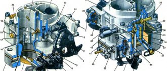
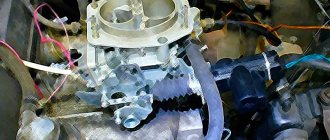
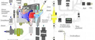
To check the solenoid valve on a VAZ 21093, you need to get to it:
Remove the air filter cover, to do this, unfasten the spring clips and unscrew the nut. Remove the air filter. Unscrew the four nuts using the “8” key. Using a screwdriver, loosen the clamp on the crankcase ventilation hose, where it is connected to the valve cover. Remove the air filter housing. Turn on the ignition Then remove the power wiring from the (EMC) Touch the power wiring terminal to the EMC terminal several times. When you touch, clicks should be clearly audible. If there are clicks, use the key “13” (or “12” or “14” - whichever is suitable) to unscrew it from the cover carburetor solenoid valve Then, with two fingers, remove the fuel jet intended for idling. Immediately pay attention to its central hole - you should remove debris from the jet using a compressor or air pump, and then make sure the hole is clean by looking at the clearance. After that, install the fuel jet back Then the EMC is installed and wrapped as described above! We put on the power cable and start the engine on the car. If there are no clicks in the solenoid valve, use the “13” key (again, whichever “12” or “14” is suitable) EMC Using an additional piece of wire, we supply the “plus” from the battery to the valve terminal, and With its body we touch the negative terminal of the battery several times
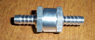
Diagram of current supply to the valve during testing
- When there are no clicks, it means the EMC is burned out.
- We replace the EMC with a working one, having first checked the serviceability
- So that you can get to the nearest spare parts store, you can slightly convert the faulty EMC into a forced open one
- We remove the fuel nozzle with two fingers, break off the plastic tip of the EMC and put the nozzle in place
- Then we insert the EMC into place and tighten it all the way by hand (here you can do this, as long as the car moves)
- We put on the power cord and start the car engine.
- However, it is worth keeping in mind that the use of such a valve causes problems with turning off the engine - it will try to continue working even after turning off the ignition
- In this situation, there is no need to panic, you just shouldn’t turn off the engine right away, but let it idle for at least five minutes, when you turn off the ignition, smoothly press the gas pedal all the way
- When there are clicks, then install the solenoid valve back
- Turn on the ignition in the car, and use a tester or test light to check the presence of a “plus” at the terminal of the EMC power supply wiring
- If there is no power, this means that the EPHH control unit has broken down
- This control unit (EPHH) cannot be repaired
- Replacing this electronic unit EPHH is not difficult, but so that you can get to the nearest spare parts store, temporarily use an additional wire to supply power to the EMC from the “+B” terminal on the ignition coil
- Another option, you can first bend the rubber cover from the bundle of wires on the forced idle block in order to connect the wiring at terminals number “4” and number “6” with a jumper.
- And the numbering order of all terminals is written on the block cover; at the edges of the connector there are numbers “7” and “1”
Place a jumper between wires “4” and “6”
- A common malfunction in the operation of the engine is associated with a malfunction of the EPH unit, in which case there is a strong decrease in rotation speed, and even a complete stop when the clutch pedal is pressed, which occurs when changing gears, or when stopping at a traffic light
- In this case, if there is a need to get to a car service center or a spare parts store, it will be enough to disconnect the connector in the circuit (EPHH), which is located near the screw for adjusting the amount of mixture
It seems like everything related to the EHR, the video will help clarify anything further.
10
Average goals:
4,50
out of 5)
Loading…
We advise you to read
VAZ 2109: maximum speed and other characteristics of the VAZ 2109 with a rotary engine and its history Replacing the VAZ 2109 seat belts on your own How to check the VAZ 2107 generator - testing methods
Timing belt diagnostics
Window lifter mechanism for VAZ 2107
The gas distribution mechanism has 2 inherent problems - loose connection of the valves to the sockets and the inability to fully open the valves.
A loose connection of the valves to the sockets is detected by the following indicators: popping noises that sometimes occur in the intake or exhaust pipes, a decrease in engine power. Factors that cause leaky valve closure may include:
- the appearance of carbon deposits on the surface of valves and seats;
- formation of cavities on working chamfers and curvature of the valve head;
- faulty valve springs.
Incomplete opening of the valves is accompanied by a knocking sound in the engine and a decrease in its power. This breakdown occurs as a result of a significant gap between the valve stem and the toe of the rocker arm. Typical timing failures include wear of camshaft gears, pushers, valve guides, camshaft displacement and wear of bushings and rocker arm axles.
Practice shows that the gas distribution mechanism accounts for approximately a quarter of all engine failures, and preventing these failures and restoring the timing takes 50% of the labor intensity of maintenance and repair work. To diagnose breakdowns, the following parameters are used:
- determine the phases of the gas distribution mechanism of the car;
- measure the thermal gap between the valve and the rocker arm;
- measure the gap between the valve and the seat.
Valve timing measurement
Such diagnostics of the engine timing belt is performed with the engine turned off using a special set of devices, including a pointer, a torque scope, a goniometer and other additional devices. In order to fix the period of opening of the intake valve on the 1st cylinder, it is necessary to rock the rocker arm around its axis, and then direct the engine crankshaft until a gap appears between the valve and the rocker arm. A goniometer for measuring the desired gap is placed directly on the crankshaft pulley.
Measuring the thermal gap between valve and rocker arm
The thermal gap is measured using a set of probes or another special device. This is a set of metal plates 100 mm long, the thickness of which must be no more than 0.5 mm. The engine crankshaft is turned up to the upper limit point, during the compression stroke of the cylinder selected for control. Directly thanks to probes of different thicknesses, alternately inserted into the formed hole, the gap is measured.
Determining the gap between valve and seat
It can be estimated by the volume of air that will escape through the seal of the closed valves. This procedure goes well with cleaning the injectors. When they have already been removed, remove the rocker arm rollers and cover all the valves. Then compressed air is supplied to the combustion chamber under high pressure. Alternately, a device is placed on any of the controlled valves that allows you to measure air flow. If the air loss exceeds the permitted limit, the gas distribution mechanism is repaired.
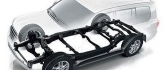
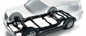
Frame
In this section we will summarize what is noted above. So, the timing drive is external, it is located on the cylinder block, covered with a casing. The camshaft is located either at the bottom, then the housing is the cylinder block, or at the top, then the housing is either a cylinder head, which is covered by a valve cover that prevents engine oil from leaking out (traditional design), or a separate block (as in a number of modern engines). By the way, the valve cover is prone to its own breakdowns, and its gasket must always be changed when it is removed. For example, if it is necessary to adjust the temperature gap, then remove the cover, adjust it, put a new gasket and cover in place, also during repairs and other types of maintenance.
Further. The valve group is either in the crankcase (this option is not used now) or in the cylinder head, the same option as with the camshaft (the most common scheme), and if the camshaft is in a different place, then part of the valve group is external, this applies to rods and rockers (overhead valves and lower camshaft).
3-stage VTEC-E
What color and how are the neutral, phase and ground wires designated in electrical engineering?
The 3-stage SOHC VTEC gas distribution mechanism is a combination of the SOHC VTEC and SOHC VTEC-E systems. Unlike all the systems described above, this system has not two operating modes, but three.
At the first stage, when the crankshaft rotation speed does not exceed ~2500 rpm, the rocker (rocker arm) of the first and second ones operate independently. The almost round cam of the second valve actuates the second valve through the rocker, i.e. in fact, the intake process is carried out through the first valve, while the second valve is only slightly opened to avoid the accumulation of fuel above it. The cam of the second valve runs idle. In the second stage, starting at approximately 2500 rpm, oil supplied through a passage in the camshaft presses on the timing rod, which connects the rockers of the first and second valves, ensuring that both intake valves operate synchronously according to the cam profile of the first valve. The remaining cams work idle. In the third mode, the oil still presses on the rod in a position where synchronous operation of both valves is ensured, while, starting from ~4500 rpm, oil begins to flow through the channel into the other cavity and put pressure on the pin, ensuring the transfer of valve control from a third cam with a larger profile, providing greater lift height.
In the low speed zone, the system ensures economical engine operation with a lean fuel-air mixture. In this case, only one of the intake valves is used. At medium speeds, the second valve comes into operation, but the valve timing and valve lift do not change. The engine in this case produces high torque. At high speeds, both valves are controlled by one central cam, which is responsible for extracting maximum power from the engine.
Phase control relay Schneider
The Schneider company is considered one of the best manufacturers of devices in the electrical power industry. The products of this company are actively used both at civilian sites and in large industrial organizations.
The advantages of the company's products include a flexible pricing policy, high quality and special conditions for customers.
The company produces circuit breakers, fuses, load switches and switchboard equipment.
In addition, the Schneider plant produces relays, switches, sockets, contactors and many other devices.
Popular models include relays:
- Control of 1-phase voltage (from 65 to 260 V and time delay from 0.1 to 10 s - RM17UBE
- 3-phase voltage control (208 to 480 V) - RM17TE
- 1-phase voltage control (160 to 280 V, 30 second delay) - EZ9C
- 3-phase voltage control (from 208 to 480 V) - RM17TT00 and others.