The working cycle of an internal combustion engine is a periodically repeating series of sequential processes occurring in each working cylinder. The main task of the work process is to convert thermal energy from the combustion of the working fluid into mechanical work, in particular into the rotational movement of the crankshaft. Car engines most often operate on a four-stroke cycle, which is completed in two revolutions of the crankshaft or four strokes of the piston and consists of intake, compression, expansion and exhaust strokes.
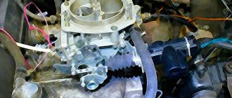
In a carburetor four-stroke engine, the operating cycle occurs as follows.
Carburetor engine duty cycle:
— Intake stroke
During this stroke, the piston descends from top dead center (TDC) to bottom dead center (BDC). At this time, the camshaft cams open the intake valve, and through this valve a fresh fuel-air mixture is sucked into the cylinder.
— Compression stroke
The piston moves from BDC to TDC, compressing the working mixture. In this case, the temperature of the mixture increases significantly. The ratio of the working volume of the cylinder at BDC to the volume of the combustion chamber at TDC is called the compression ratio. The compression ratio is a very important parameter; usually, the higher it is, the greater the fuel efficiency of the engine. However, an engine with a higher compression ratio requires higher octane fuel, which is more expensive. Expansion stroke, or power stroke
Shortly before the end of the compression cycle, the air-fuel mixture is ignited by a spark from the spark plug. As the piston moves from TDC to BDC, the fuel burns and, under the influence of the heat of the burned fuel, the working mixture expands, pushing the piston. When gases expand, they do useful work, so the stroke of the piston during this stroke of the crankshaft is called the “power stroke.” It is almost impossible to completely clean the engine cylinders from combustion products, therefore, with the subsequent intake of a fresh combustible mixture, it moves with residual exhaust gases and is called the “working mixture”. The degree to which the engine crankshaft is “underrotated” to TDC when the mixture is ignited is called the ignition timing angle. Ignition timing is necessary so that fuel combustion has time to completely end by the time the piston reaches BDC, that is, for the most efficient operation of the engine. Fuel combustion takes almost a fixed time, so to improve engine efficiency, you need to increase the ignition timing as the speed increases. In older engines, this adjustment was made by a mechanical device (centrifugal and vacuum regulator acting on a chopper). Modern engines use electronics to adjust the ignition timing.
Watch the animation, it clearly demonstrates the operation of a four-stroke engine.
— Release stroke
After BDC of the operating cycle, the exhaust valve opens and the upward moving piston forces the exhaust gases out of the engine cylinder. When the piston reaches TDC, the exhaust valve closes and the cycle begins again.
How to diagnose the condition of the engine by the color of the exhaust gases, read the corresponding article.
The residual gas coefficient characterizes the degree of contamination of the fresh charge with exhaust gases and is the ratio of the mass of combustion products remaining in the cylinder to the mass of the fresh combustible mixture. For carburetor engines, the residual gas coefficient is in the range of 0.06-0.12.
In relation to the power stroke, the intake, compression and exhaust strokes are auxiliary.
History of creation
In the 18th century, many inventors worked to create power units that could replace the steam engine. The appearance of devices in which fuel would not be burned in a furnace, but directly in the engine cylinder, became possible after the French inventor Philippe Le Bon discovered illuminating gas in 1799. Two years later, he also designed a gas power unit, where the gas-air mixture was ignited in the cylinder. It had 1 double-acting working cylinder (combustion chambers were located on both sides of the piston, and the working mixture in them was ignited alternately). And only many years later a more advanced four-stroke engine appeared, which found wide application in many industries.
Such an engine was first demonstrated by the German engineer August Otto in 1877. This happened after the Belgian inventor Jean Etienne Lenoir proposed igniting a combustible mixture using an electric spark. Its appearance was also facilitated by the invention of a device that made it possible to evaporate liquid fuel and ensure the preparation of a working gas-air mixture (carburetor).
Serial production of four-stroke gasoline engines began in 1883. Then the German engineer Gottlieb Daimler proposed using hot tubes inserted inside the cylinders to ignite the gas-air mixture.
In a four-stroke diesel engine, working processes occur as follows
— Intake stroke
When the piston moves from TDC to BDC, due to the resulting vacuum, atmospheric air enters the cylinder cavity through the open intake valve.
— Compression stroke
The piston moves from BDC to TDC. The intake and exhaust valves are closed, as a result of which the upward moving piston compresses the air present in the cylinder. For fuel to ignite, the temperature of the compressed air must be higher than the auto-ignition temperature of the fuel.
— Expansion stroke, or power stroke
As the piston approaches TDC, diesel fuel is injected into the cylinder through a nozzle, supplied by a high-pressure fuel pump (HPF). The injected fuel, mixing with heated air, self-ignites and the combustion process begins, characterized by a rapid increase in temperature and pressure. Under the influence of gas pressure, the piston moves from TDC to BDC. A working process is taking place.
— Release stroke
The piston moves from BDC to TDC and the exhaust gases are pushed out of the cylinder through the open exhaust valve. After the end of the exhaust stroke, with further rotation of the crankshaft, the working cycle is repeated in the same sequence.
Study and read thermal and dynamic calculations of 4-stroke internal combustion engines in this free program
This video shows the operation of a real engine. The camera is built into the cylinder of the block.
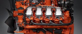
Unit design
The camshaft of a four-stroke engine is located in the cylinder cover. It is driven by a drive wheel mounted in the crankshaft. The camshaft opens and closes one of the valves: exhaust or intake, depending on the location of the piston. The camshaft also contains cams that operate the valve rocker arms.
Once triggered, the rocker arms It is important that there must be a thermal gap (narrow gap) between the adjusting screw and the valve. When heated, the metal expands, so if the gap is too small or there is none at all, the valves cannot completely close the exhaust and intake passages.
at the intake valve should be smaller than at the exhaust valve, because the exhaust gases are hotter than the mixture. Accordingly, the intake valve heats up less than the exhaust valves.
Disadvantages of four-stroke engines:
All idle strokes (intake, compression, exhaust) are accomplished using the kinetic energy stored by the crank mechanism and associated parts during the power stroke, during which the chemical energy of the fuel is converted into mechanical energy of the moving parts of the engine. Since combustion occurs in fractions of seconds, it is accompanied by a rapid increase in the load on the cylinder cover (head), piston and other parts of the internal combustion engine. The presence of such a load inevitably leads to the need to increase the mass of moving parts (to increase strength), which in turn is accompanied by an increase in inertial loads on moving parts.
Disadvantages include the need to adjust the thermal clearance of the valves, a larger number of parts and, accordingly, each of them will need to be replaced with a working one at some point. Four-stroke internal combustion engines are larger, their parts are more voluminous and complex. To carry out repairs of such engines, it is necessary to use heavy garage equipment: tilting stands, stands for repairing internal combustion engines, a crane, etc.
What are dead spots and engine cycles?
The number of stages included in one working cycle of an internal combustion engine (ICE) is usually calculated based on the number of piston strokes in the cylinder. These stages are called engine strokes. The stroke of the piston is directly determined by its movement from one extreme point to another. They are called dead, because if the piston stops at such a point, it will not be able to start moving without external influence. In simple words, dead points are positions at which the movement in the current direction of the piston stops and it begins to reverse.
Dead spots and piston stroke of internal combustion engines
There are two dead spots:
- Lower (BDC) – the position at which the distance between the piston and the axis of rotation of the crankshaft is minimal.
- Top (TDC) - the position at which the cylinder is at the maximum distance from the axis of rotation of the engine crankshaft.
In English-language documentation, TDC is designated as TDC (Top Dead Center), and BDC is designated BDC (Bottom Dead Center).
There are engines whose operating cycle can consist of two or four strokes. Based on this, they are divided into two-stroke and four-stroke engines.
Advantages of four-stroke engines:
- Economical fuel consumption due to fewer working strokes per unit of time;
- Reliability is due to the thermal regime, which is softer in 4-stroke internal combustion engines;
- The engine is much quieter than its two-stroke counterpart.
Unlike a two-stroke engine, in which the crankshaft, crankshaft bearings, compression rings, piston, piston pin and cylinder are lubricated by adding lubricant to the fuel, the crankshaft of a four-stroke engine is force-lubricated by pressure. Significantly less carbon deposits form on the piston surface, muffler walls and exhaust system. In addition, in a 2-stroke engine, the fuel mixture is released into the exhaust pipe and affects the environment. The environment has a separate problem.
How it all began
In the 19th century there were already engines, but they were mainly large mechanisms powered by steam. Of course, they partially provided for the developing industry, but had many disadvantages.
They were heavy, had low efficiency, large dimensions, required a lot of time to start and stop, and required skilled workers for operation.
Industrialists needed a new unit without the listed disadvantages; they already understood what a four-stroke engine means. And how, under certain conditions, it can be used to increase profits.
It was developed by the inventor Eugene-Alphonse Beau de Rochas, and in 1867 it was embodied in metal by Nikolaus August Otto.
At that time it was a miracle of technology. The internal combustion engine was characterized by low operating costs, small size and did not require the constant presence of maintenance personnel.
The device worked according to a special algorithm, which is still called the “Otto cycle”. 8 years later, after the launch of the first copy, Otto’s company was already producing more than 600 power units per year.
Very quickly, due to their autonomy and compactness, internal combustion engines became widespread.
What determines the power of a four-stroke internal combustion engine?
Everything seems to be clear here - the power of a piston engine is mainly determined by:
- cylinder volume;
- compression ratio of the working mixture;
- rotation speed.
You can also increase the power of a four-stroke engine by increasing the throughput of the intake and exhaust strokes and increasing the diameter of the valves (especially the intake ones).
Also, maximum power is obtained when the cylinders are filled to the maximum; for this purpose, turbines for forced air pumping into the cylinder are used. As a result, the pressure in the cylinder increases and, accordingly, the engine efficiency increases significantly.
Compression stroke - two-stroke engine
The piston of a two-stroke engine rises from the BDC of the piston (in this position it is in Fig. 2) to the TDC of the piston (the position of the piston in Fig. 3), blocking first the purge 2 and then the exhaust 3 windows of the cylinder of a two-stroke engine. After the piston closes the outlet hole in the cylinder, compression of the previously entered fuel mixture begins. At the same time, in the crank chamber 1, due to its tightness and after the piston closes the purge windows 2, a vacuum is created under the piston, under the influence of which a combustible mixture enters the crank chamber of a two-stroke engine from the carburetor through the inlet window and the opening valve.
The first stroke is intake.
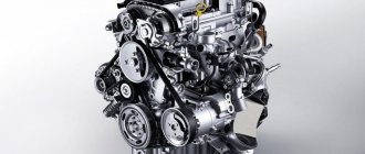
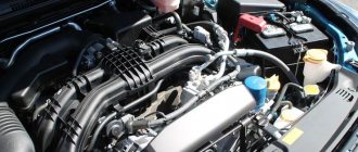
Modern engine structure
car, design of systems and mechanisms
The piston moves from TDC to BDC, and purified air enters the cylinder through the open intake valve (due to the vacuum created by the piston). The air is mixed with a small amount of exhaust gases remaining from the previous cycle, the temperature rises and at the end of the intake stroke reaches 300-320 K, and the pressure 0.08-0.09 MPa. The cylinder filling coefficient is 0.9 or higher, i.e. more than that of a carburetor engine.
The operating principle of a 4-stroke gasoline (diesel) engine.
The operating principle of a 4-stroke gasoline (diesel) engine.
1st stroke suction (filling). The piston moves from TDC to BDC, the intake valve is open. Under the influence of the pressure difference resulting from the movement of the piston, air (in a diesel engine) or a gasoline-air mixture (in a gasoline engine) fills the cylinder through the inlet port.
2nd stroke compression. The piston moves from BDC to TDC, all valves are closed. The pressure and temperature in the cylinder rise. At the end of the compression stroke, a high voltage is applied to the spark plug (gasoline engine), a spark jumps between the electrodes of the spark plug and ignites the gasoline-air mixture or (diesel) - diesel fuel is supplied through a high-pressure nozzle, which is ignited by the air heated during the compression process.
3rd stroke working stroke. The piston moves from TDC to BDC, all valves are closed. At the beginning of the stroke, combustion of the fuel that began at the end of the compression stroke continues. The temperature and pressure of gases increases. Pressure is transferred to the piston and moves it to BDC. The thermal energy of the burned fuel is converted into mechanical work of the piston movement.
4th bar release. The piston moves from BDC to TDC, the exhaust valve is open. Ejection occurs
exhaust gases from the cylinder.
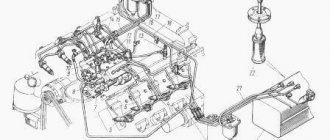
Timing parts.
The gas distribution mechanism (GRM) is designed for timely, in accordance with the order of operation of the cylinders, opening and closing valves, ensuring the operating process of the engine. It consists of a camshaft connected by a special gear to the crankshaft by a chain or timing belt. This is necessary so that the movement of the pistons, which is provided by the crankshaft, corresponds to the opening and closing of the valves. Consequently, the orientation of the shafts relative to each other must be strictly defined. This is ensured by the coincidence of marks applied to the gears (sprockets) of the shafts connected by a chain or toothed belt.
Cams are applied to the camshaft, which, with their protruding part, ensure the opening of the valves, running against it or transmitting this movement through the rocker arm.
In addition, the timing belt includes intake and exhaust valves with springs and valve stem seals.
Cooling system.
The cooling system of an internal combustion engine is a set of devices that provide the supply of cooling medium to heated engine parts and the removal of excess heat from them into the atmosphere, which should provide the most favorable degree of cooling and the ability to maintain the thermal state of the engine within the required limits under various modes and operating conditions.
There are three types of cooling systems for internal combustion engines: air, liquid and hybrid.
Air cooling: The cylinder jacket is freely blown with air, thereby taking away most of the engine heat. It is the simplest, as it does not require complex parts and control systems. The disadvantage of the system is the small heat capacity of the air, which does not allow a large amount of heat to be evenly removed from the engine and, accordingly, the creation of compact, powerful power plants.
Liquid cooling: The engine cylinders are cooled by liquid, after which it returns to the expansion tank. It is a very old type of cooling system; currently this type is not used in the automotive industry, since the liquid does not have time to cool, so engines equipped with this cooling system cannot operate for a long time.
Hybrid type: Nowadays the hybrid system is called liquid. In fact, it is still hybrid, since air is also involved there.
combines the above systems: heat is removed from the cylinders by liquid, after which, at a distance from the heat-loaded part of the engine, it is cooled in radiators by air. Consists of a cylinder block cooling jacket, a cylinder block cooling head, a radiator, a fan, a fluid pump, a thermostat, an expansion tank and a temperature sensor. This type is used on all modern cars. The coolant cools the cylinders and then cools itself in the radiator. In this system there are two circles of fluid circulation - large and small. The large circle consists of the engine block, water pump, radiators (including the interior heater), and thermostat. The small circle includes the engine block, water pump, thermostat. The adjustment of the amount of liquid between liquid circulation circles is controlled by a thermostat. The small cooling circle is designed to quickly bring the engine into efficient thermal mode.
A liquid cooling system usually includes the following elements:
double walls of cylinders, the space between which is filled with coolant (for example, water or antifreeze);
a heat exchanger or radiator consisting of tubes and cavities;
a fan consisting of a hub and blades, the rotation of which ensures air pumping between the radiator tubes;
a centrifugal pump to ensure circulation of coolant in the system;
pipelines connecting the engine to the radiator.
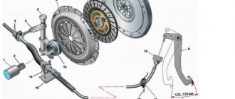
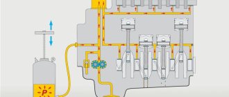
Lubrication system.
The lubrication system is designed to supply oil to rubbing parts, partially cool them and remove wear products. The lubrication system consists of:
- oil pan,
- oil pump with oil receiver,
- oil filter,
— channels for supplying oil under pressure drilled in the cylinder block, cylinder head and other engine parts.
The oil pan is a reservoir for storing oil. When you pour oil through the oil filler neck, it flows through the voids inside the engine and down into the oil pan. The level in the oil pan can be measured with an oil dipstick through the hole in the engine crankcase.
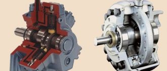
The oil pump supplies oil under pressure (through a filter and channels) to the rubbing parts of the crank and gas distribution mechanisms. The pump consists of two gears and is driven by the engine crankshaft. As the gears rotate, the teeth capture oil and pump it into the main oil line.
The pressure reducing valve serves to limit the pressure in the engine oil channel system. When there is excess pressure, the spring is compressed and some of the oil flows back.
The oil filter serves to clean the oil passing through it from mechanical impurities. It is installed immediately after the pump and passes through itself all the oil that enters the oil line. Most often, the filter has a non-separable design and must be replaced simultaneously with a scheduled engine oil change.
Internal combustion engines use a combined lubrication system - under pressure and by spraying. Oil is supplied to the most heavily loaded rubbing surfaces under pressure, and the remaining parts of the engine mechanisms are lubricated by oil splashes and oil mist. The oil reaches the bearings of the crankshaft and camshaft through the channels of the system, of course, under pressure. Having done its job, that is, lubricated, cooled a little and taking wear products with it, the oil flows back into the engine sump.
When the crankshaft rotates, its cranks hit the surface of the oil in the oil pan, resulting in oil splashes and mist that fall on the cylinder bore, piston and piston pin. All moving parts of the crank and gas distribution mechanisms seem to be bathed in oil. This achieves high wear resistance of modern engine components.
Intake-exhaust system.
The intake system (another name is the intake system) is designed to admit the required amount of air into the engine and form a fuel-air mixture.
The intake system has the following general arrangement:
Air intake (provides air intake from the atmosphere);
air filter (to clean the air from mechanical particles);
throttle valve (regulates the amount of incoming air in accordance with the amount of injected fuel);
intake manifold (distributes the air flow among the engine cylinders and gives it the necessary movement);
connecting pipes.
To improve the filling of cylinders with air and increase power, turbocharging is used in the design of the intake system of modern gasoline and diesel engines.
The exhaust system (another name for the exhaust gas system, exhaust system) is designed to remove exhaust gases from the engine cylinders, cool them, and reduce noise and toxicity.
The exhaust system has the following device:
an exhaust manifold;
muffler exhaust pipe;
vibration-isolating coupling (bellows);
pre-silencer (resonator);
main muffler;
connecting pipes.
All structural elements of the exhaust system are located under the bottom of the car.
The exhaust manifold bears the largest temperature load. The muffler exhaust pipe is attached to the exhaust manifold. In order to isolate the structural elements of the exhaust system from engine vibration, a Bellows is used, which is a flexible metal hose covered with a steel sheath. The muffler, as the name suggests, is designed to reduce noise and cool exhaust gases.
Ignition system.
The ignition system is designed to ignite the fuel-air mixture of a gasoline engine.
Currently, the following types of ignition systems are used on cars:
contact ignition system;
contactless (transistor) ignition system;
electronic (microprocessor) ignition system.
In a contact ignition system, the accumulation and distribution of electrical energy among the cylinders is controlled by a mechanical device - a switch-distributor. A further development of the contact ignition system is the contact transistor ignition system.
Unlike a contact system, a contactless ignition system uses a transistor switch with a contactless pulse sensor to control energy accumulation.
The microprocessor ignition system uses an electronic control unit.
The ignition system has the following general device:
power source (generator and battery);
ignition switch;
energy storage control device (chopper, transistor switch, electronic control unit);
energy storage (ignition coil, capacitor);
energy distribution device (mechanical distributor, static distributor);
high voltage wires;
spark plug.
The principle of operation of the ignition system is the accumulation and conversion of the low voltage (12V) ignition coil of the vehicle's electrical network into high voltage (up to 30,000V), distribution and transmission of high voltage to the corresponding spark plug and the formation of a spark at the right moment on the spark plug.
Operating principle of nuclear power plants.
A nuclear power plant is a complex of technical structures designed to generate electrical energy by using the energy released during a controlled nuclear reaction. Uranium is used as a common fuel for nuclear power plants. The fission reaction takes place in the main unit of a nuclear power plant - a nuclear reactor.
1) Using pumps, water is pumped through the reactor core, heating up to 320 degrees due to the heat released during the nuclear reaction.
2) The heated coolant is divided into steam and water.
3) Pressurized steam is supplied to the steam turbine.
4) The turbine drives the generator rotor.
5) In the condenser, the steam is cooled and converted into input.
6) The cooled coolant re-enters the reactor.
Advantages of nuclear power plants: Small volume of fuel used and the possibility of its reuse after processing, Relatively low cost of energy, especially thermal energy; Possibility of placement in regions located far from large water and energy resources.
Disadvantages of nuclear power plants: Irradiated fuel is dangerous: it requires complex, expensive, time-consuming processing and storage measures; From a statistical point of view, major accidents are very unlikely, but the consequences of such an incident are extremely severe.
Operating principle of CHP
thermal power plants are power plants that generate electricity by converting the chemical energy of fuel into the mechanical energy of rotation of the electric generator shaft. The generation of electricity in a thermal power plant involves many successive stages, but the general principle of its operation is very simple. First, the fuel is burned in a special combustion chamber (steam boiler), which releases a large amount of heat, which turns the water circulating through special pipe systems located inside the boiler into steam. The constantly increasing steam pressure rotates the turbine rotor, which transfers rotational energy to the generator shaft, and as a result, electric current is generated.
The steam/water system is closed. The steam, after passing through the turbine, condenses and turns back into water, which additionally passes through the heater system and again enters the steam boiler. The main disadvantage of all thermal power plants is the type of fuel used. All types of fuel that are used at thermal power plants are irreplaceable natural resources that are slowly but steadily running out. That is why, at present, along with the use of nuclear power plants, a mechanism for generating electricity using renewable or other alternative energy sources is being developed.
Operating principle of hydroelectric power station.
A hydroelectric power station (HPP) is a power plant that uses the energy of water flow as an energy source. Hydroelectric power plants are usually built on rivers by constructing dams and reservoirs.
Peculiarities
The cost of electricity at Russian hydroelectric power plants is more than two times lower than at thermal power plants.[1]
Hydroelectric generators can be turned on and off quite quickly depending on energy consumption
River flow is a renewable energy source
Significantly lower impact on the air environment than other types of power plants
Hydroelectric power plant construction is usually more capital intensive
Efficient hydroelectric power plants are often more distant from consumers
Reservoirs often occupy large areas, but since about 1963, protective structures began to be used (Kiev Hydroelectric Power Station), which limited the area of the reservoir, and, as a result, limited the area of the flooded surface (fields, meadows, villages).
Dams often change the nature of fisheries because they block the passage of migratory fish to spawning grounds, but they often contribute to the increase in fish stocks in the reservoir itself and the implementation of fish farming.
Operating principle: The operating principle of a hydroelectric power station is quite simple. A chain of hydraulic structures provides the necessary pressure of water flowing to the blades of a hydraulic turbine, which drives generators that produce electricity.
The required water pressure is formed through the construction of a dam, and as a result of the concentration of the river in a certain place, or by diversion - the natural flow of water. In some cases, both a dam and a diversion are used together to obtain the required water pressure.
The power of a hydroelectric power station directly depends on the water pressure, as well as on the efficiency of the generator used.
operating principle of a 4-stroke gasoline (diesel) engine.
1st stroke suction (filling). The piston moves from TDC to BDC, the intake valve is open. Under the influence of the pressure difference resulting from the movement of the piston, air (in a diesel engine) or a gasoline-air mixture (in a gasoline engine) fills the cylinder through the inlet port.
2nd stroke compression. The piston moves from BDC to TDC, all valves are closed. The pressure and temperature in the cylinder rise. At the end of the compression stroke, a high voltage is applied to the spark plug (gasoline engine), a spark jumps between the electrodes of the spark plug and ignites the gasoline-air mixture or (diesel) - diesel fuel is supplied through a high-pressure nozzle, which is ignited by the air heated during the compression process.
3rd stroke working stroke. The piston moves from TDC to BDC, all valves are closed. At the beginning of the stroke, combustion of the fuel that began at the end of the compression stroke continues. The temperature and pressure of gases increases. Pressure is transferred to the piston and moves it to BDC. The thermal energy of the burned fuel is converted into mechanical work of the piston movement.
4th bar release. The piston moves from BDC to TDC, the exhaust valve is open. Ejection occurs
exhaust gases from the cylinder.