The shaft is steel, on its corrugated surface, a steel bushing, pole pieces and slip rings are rigidly fixed by pressing.
Features of the generator When using, adhere to the following rules: 2.
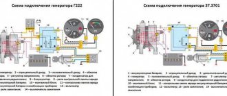
The principle of operation of the generator set G, using the example of its inclusion in the electrical circuit of MAZ vehicles, is shown in Fig. Correct connection of the generator "KAMAZ" Euro 2. Connect generator "KAMAZ" Euro 2.
On the car, the regulator is turned off. The field winding is powered by a direct current source such as a battery. The generator is cooled by continuous ventilation. The ball bearing, located on the shaft on the drive side, is fixed against axial movement. If necessary, verify the serviceability of indicating devices using known good ones.
Current-speed characteristic of the generator Fig. When installing the generator on the engine, you must: 2.
In the first case, it may be a cooling or fuel supply system consisting of diverse elements. GENERATOR AND RELAY 702 FOR INDICATION OF GENERATOR OPERATION
Characteristics of generators for YaMZ engines
Generators for powerful diesel engines must provide stable DC voltage and sufficient rectified current power. Thus, the YaMZ 236 generator, which supplies engines of various modifications of BelAZ, Ural, KrAZ (model 1702.3771), is characterized by a rectified current of 50A and a rated voltage of 28V.
YaMZ engines are equipped with domestic electrical equipment, Radiovolna, ZiT, and Belarusian BATE generators. The G1000VK11.1 model for the YaMZ 238 engine produced is considered reliable.
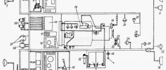
Electrical diagram of the MAZ 5551 car
Typical electrical diagram of a MAZ 5551 truck. To enlarge the diagram, click on it.
On the diagrams, letters indicate the colors of the wires: B - white, G - blue; J - yellow; O - orange; P - pink; C - gray; 3 - green; K - red; Kch - brown; Ch - black; F - purple. The vehicle's power supply system consists of two sources: batteries and an alternating current generator set. In addition, the system includes a number of intermediate relays, a battery mass switch and a key switch for instruments and starter. MAZ car power supply system
MAZ battery connection diagram
MAZ vehicles are equipped with batteries of the 6ST-182EM or 6ST-132EM type. The voltage of each battery is 12 V. Two batteries are connected in series, which increases the operating voltage to 24 V.
Fuses in the MAZ electrical circuit
Electrical diagram of MAZ 5551, MAZ 5433, MAZ 54331 and MAZ 5433
11.3704000 Control button for remote activation of the mass 11.3714010 Cabin light 11.3747010 Relay 11.3812010 Voltage indicator 1102.3740999 Fuel solenoid valve 111.3722000 Fuse block 12.3802010 Electric speedometer 1202.3 741000 Additional resistor with electrothermal relay 124.3803010 Warning lamp 13.5205009 3-brush windshield wiper 13.5205010 3-brush windshield wiper 131-3839600 Air clogged sensor filter 14.3726010 Side turn signal repeater 20.3843010 Electric speedometer sensor 25.3708000-01 Starter assembly 32.3710000 Hazard switch 341.3711010 Headlight 47KV Socket 47KV 500-3724057-D Jumper battery 504-3724062-Zh Wire from batteries to starter 5335-3724071-01 Wire "ground" Price 5336-3724039-11 Power cable for portable lamp socket 5336-3724060-02 Ground wire 5336-3724069-10 Ground switch wire 5336-3724078-01 — 5336-3724188-01 — 5336-3900032 — 5 433-3724028 -01 Harness along the side member 5433-3724328-01 — 54331-3724021 Harness for the rear light left 54331-3724026 Harness for the rear light right 5551-3724008 Harness main 5551-3724021 Harness for the rear light left Price 5551-372402 6-01 Right rear light harness 5551-3724028 -03 Harness on the side member 5551-3724046-02 Harness on the roof 5551-3724056 Wire from the battery to the ground switch 5551-3724160 Harness right 5551-3724328-01 - 6ST-190A Battery BM163B-3806600 -D Fuel level sensor VK343 -3709000-01.03 Switch VK343-3709000-01.04 Switch VK343-3709000-01.16 Switch VK343-3709000-01.35 Switch VK353-3703999 Starter switch VK353-3704000 Starter switch VK403 A-3716000 Switch VK416B-3709000-01 Switch for lighting the instrument panel with rheostat VK856- 3707999 Starter switch VK860B-3737000 Ground switch G273V-3701000 Alternator KT127-3749999 Contactor LV211-3714328 Lamp holder (44737473129) MM111D-3810600 Emergency oil pressure sensor MM1 24D-3810600 Emergency air pressure sensor MM125D-3810600 Pneumatic brake signal switch, blocking MM370-3829010 Air pressure sensor ME237-3730000 Electric motor P145-3726010 Light and turn switch P147-3709000-04.11 Switch P147-3709000-09.09 Switch P150-3709000-09.11 Switch PD308B- 3715300 Engine compartment lamp PD511B-3803010 Control lamp block PD512B-3803010 Indicator lamp block PR112-3722000-01 Fuse block PR112-3722100-A Fuse insert PR112-3722200-A Fuse insert PS300A3-3723149 Plug PS325-3723149 Plug PS400-3723100 Socket plug PF1306-3712010 Sidelight PF233A-3737999 Signal light RS103-3707999 Starter relay RS530-3721000 Relay RS531-3721000 Noise alarm RS951A-3726010 Turn signal breaker S306-3721000-G Signal (set. up to 1988) S307-3720999 Signal (installed before 1988) S313-3721000 Signal (installed since 1988) S314-3721000 Signal (installed since 1988) S314G-3721000 Signal (installed since 1988) d.) TM100V-3808000 Water temperature indicator sensor TM112-3810000 Water temperature indicator sensor UB170-3806010-01 Fuel level indicator UK168-3810010 Pressure indicator receiver UK170-3810010-02 Pressure indicator UK171-3807010-01 Index water temperature FG152A-3742999 Headlight fog lamp FG152A-3743000 Fog lamp FP130-3716010-B Rear left lamp FP130-3716010-G Rear right lamp FP135-3716010-G Reversing lamp FP310E-3731009 Retroreflector YA120M1-3701999 In integral voltage regulator
Selection of generators for KamAZ and Ural trucks
Diesel generators for KamAZ and Ural trucks are varied in technical characteristics, depending on the model and engine power. To the defining characteristics of the G273V1
(YMZ-236, YaMZ-238 engines for Ural trucks) include maximum current (50 A), rated voltage (28 V), excitation current up to 4.1 A, weight 5.2 kg. An important improvement to the model was the possibility of seasonal adjustment. The integrated device in the “Winter” mode increases the starting voltage to 30V.
More powerful model 6562.3701
used in KamAZ trucks with KamAZ-7403, KamAZ-4310 engines. At the same rated voltage, a generator weighing 9.25 kg produces a higher maximum rectified current (90 A), reaches a power of 2520 W, and reaches a shaft speed of 6000 rpm at a current of 75 A.
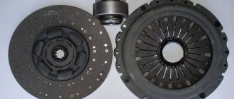
Device
The generating set (GS) is a three-phase synchronous machine with excitation from an external power source and a rectifier unit. To control the output voltage and maintain it within specified limits, an integrated voltage regulator is installed.
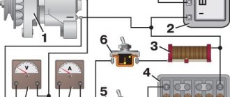
The operating principle of the generator is based on the phenomenon of electromagnetic induction. The rotating magnetic field of the rotor, crossing the stator windings, induces an EMF in them, which is connected to the load through the rectifier unit. The main elements of the generator are:
- rotor;
- stator;
- front and back covers with built-in rectifier;
- brush holders with integral voltage regulator;
- fan pulley and impeller.
The generator rotor is a shaft made of electrical steel, on which an excitation winding (inductor) is wound. Power is supplied to it through 2 contact rings installed on the side of the back cover. 12 beak-shaped magnets are pressed onto the shaft. Ball bearings are installed at both ends of the rotor.
The stator winding is three-phase and consists of 36 coils. Each phase has 12 series-connected windings located in the stator slots and offset from one another by 120°. The electrical connection of the poles is made according to the “star” principle. The phase output terminals are connected to the rectifier unit.
A rectifier unit, voltage regulator and brush holders are installed on the back cover of the generator. The body elements are cast from aluminum alloy. In the center of each cover there is a place for installing a bearing. The fan impeller is installed on the rear end of the shaft, held from turning by a key and secured with a nut. In a similar way, a double-groove pulley is attached to the armature shaft in the front part of the GU. The design of generators of different models of MAZ cars is the same and differs only in the way they are connected to the network.
Placing an order
The Yaroslavl assortment provides the opportunity to order generators for the entire range of YaMZ, TMZ, KamAZ, MTZ, MMZ engines.
Minimum trade margins and direct contacts with manufacturers provide tangible advantages:
- stable affordable prices;
- fast order fulfillment from warehouse stocks;
- manufacturer's guarantees;
- delivery of the order to the regions of the Russian Federation and the CIS.
To order a generator for KamAZ, KrAZ, Ural, BelAZ, Tonar, MZKT vehicles, just a phone call to the numbers (4852) 60 85 80
or by mail
You will receive qualified advice on the interchangeability of generators, availability, and prices from our managers.
How to check the generator without removing it from the car
There are two ways, using a multimeter and without it at all. The first, relatively new one, is to check the voltage at the battery terminals, and the second, old and proven one, is almost the opposite - the battery terminal must be removed with the engine running.
- Checking the battery with a multimeter first occurs at rest - the voltage should be in the range of 12.5-12.8 V. Then you need to measure the readings with the engine running, if 13.5-14.5 V is observed at 2 thousand revolutions, then everything is in order. Moreover, on new cars, even 14.8 V is quite normal, as manufacturers claim - the abundance of electronics affects it. In conclusion, it remains to check the voltage under load , that is, by connecting consumers - the stove, headlights, heating, radio. A dip in the range of 13.7–14.0 V is considered acceptable, but 12.8–13 V already indicates a malfunction.
- The second method, like many “old-fashioned” ones, is simple and trouble-free, but at the same time quite dangerous and requires care . It allegedly works both on VAZs and on relatively new cars, like the Aveo. What is the point - loosen the bolt securing the negative terminal of the battery with a 10mm wrench, start the engine and give a small load, turning on one of the consumers, for example, the headlights. Then remove the terminal while the engine is running - if it does not stall and the headlights do not dim, then everything is absolutely fine with the generator, otherwise you can be sure that it is broken. You should try this method at your own peril and risk.
Having determined that there is a malfunction, you should dismantle and check the removed generator with a multimeter, a light bulb, and visually. Each of its elements is subject to verification separately.
Maz 5440 / 6430 euro - fuses and relays
Maz 5440 and Maz 6430 are the general designations for two series of truck tractors of the Minsk Automobile Plant produced from 1997 to the present with various modifications and changes (643008, 6430A8, 643005, 6430A5, 6430A4, 631208, 6312A8, 544009, 5440A9 , 544008, 5440A8, 544005, etc.) and generations (Euro 3 4 5 6). In this article you will find a description of the most popular fuse and relay blocks Maz 5440 and Maz 6430 with diagrams and their locations.
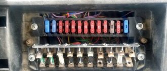
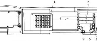
Block in the cabin
The main fuse and relay box is located in the passenger compartment, in the middle of the dashboard, on the passenger side and is closed with a protective cover.
The design of the block and the purpose of the elements in them depend on the year of manufacture and the level of equipment of the MAZ. The current designation for your vehicle will be printed on the back of the protective cover. Check the purpose, and in case of difficulty, contact your dealer.
Option 1
Description of fuses
p, blockquote 8,0,0,0,0 —>
- 16A refrigerator
- 16A (+) from the lock for ABS brakes
- 16A air dryer, heaters
- 16A (+) from the generator for ABS brakes
- 16A from generator for engine electronics
- 8A turns
- 8A lights
- 8A tractor brake signals
- 8A (+) with brake signal relay
- 8A reverse light
- 8A trailer brake lights
- 8A alarm
- 8A heater control unit
- 8A thermostat timer, radio
- 8A standard heater fan
- 8A independent heater heaters
- 8A high beam right headlight
- 8A high beam left headlight
- 8A low beam right headlight
- 8A low beam left headlight
- 8A size reserve
- 8A heated mirrors, power windows
- 8A fan clutch
- 8A electrical signals
- 8A voltage regulator, engine stop
- 8A engine stop valve
- 8A switches
- 8A wiper
- 8A power supply for other indicator lamps
- 8A power supply for emergency warning lamps
- 8A power supply for devices
- —
- 8A tachograph
- 6A cabin lamps
- 6A rear fog lights
- 8A additional high beam headlights
- 8A front fog lights
- 8A right side trailer
- 8A left side of trailer
- 8A instrument lighting
- 8A right side of the tractor
- 8A left side of the tractor