Gearbox: description of shift pattern
Gear changes are powered by a five-speed manual transmission, which is equipped with every car in this series. Synchronizers were added to all speeds except fifth. The location of the lever that adjusts the indicators as needed is the lid at the top.
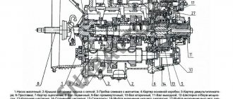
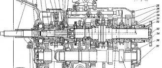
Gearbox of a ZIL-131 car
1 - drive shaft; 2, 18, 24, 34, 35 and 37 - bearings; 3 — drive shaft bearing cover; 4 — synchronizer for fourth and fifth gears; 5 and 31 — fourth gear gears; 6 and 29 — third gear gears; 7 — fork for shifting fourth and fifth gears; 8 — fork for shifting second and third gears; 9 — retainer ball; 10 — clamp spring; 11 — lock pin; 12 — lock ball; 13 — synchronizer for second and third gears; 14 and 27 - second gear gears; 15 — fork for shifting first gear and reverse gear; 16 — first gear and reverse gear; 17 — ventilation tube; 19 — spacer ring; 20 - flange; 21 - flange nut; 22 — intermediate shaft bearing cover; 23 — bearing mounting nut; 25 — gearbox housing; 26 — driven shaft; 28 — reverse gear; 30 — fourth gear bushing; 32 — intermediate shaft; 33 — constant mesh gear of the intermediate shaft; 36 — drive shaft bearing fastening nut; 38 — spacer sleeve; 39 — axis of the reverse gear block; 40 — reverse gear block; 41 — filler plug; 42 — drain plug; 43 — gearbox cover; 44 — lever housing; 45 — lever spring; 46 — lever; 47 - fuse stop.
For such a ZIL 131 gearbox, in accordance with the diagram with gear ratios, it looks like this:
Gear No. 1 is associated with complete off-road driving. A typical location is “on one shoulder” with a reverse drive. The goal is to increase the swing speed. For example, if loose dirt and snow are located everywhere. To get out of this situation, it is enough for 1st and reverse gear to be engaged alternately. You can view the list of parts for it and, in particular, the intermediate rings of the S/I needle bearing of the gear for the first gear in the website catalog.
The box has a dry weight of one hundred grams. For the ZIL 131 gearbox, the switching circuit works quite quickly.
SYNCHRONIZER
Synchronizers ensure silent operation when turned on. The difference in the rotation speed of the synchronizer clutch and the engagement of the gear is smoothly equalized due to the friction force that arises between them. The gearbox shift mechanism has a locking device that holds the shift rods in the required position.
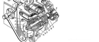
Synchronizer ZIL-130
The synchronizer for LAZ-695, LAZ-697 buses and the ZIL-130 car (Fig. 132) works as follows.
When clutch 11 is moved to the left using the shift fork, the conical bronze ring will move with it and press against the conical surface of gear 1. The conical rings 7 and the clutch ]] are not connected rigidly to each other, but through three locking pins 5 with balls and a spring. Gear 1 and rings 7 rotate at different peripheral speeds. Until these speeds become equal due to the friction force, coupling 11 will shift (Fig. 132, b).
Synchronizer ZIL-130
Both bronze rings 7 are rigidly connected to each other using pins 12. The coupling 11 will move until the conical surface 10 of the coupling rests against the conical surface 9 of the pin (Fig. 132, a and d). When the speeds of the synchronizer rings 7 and the gear cone 1 are equalized, the pin 12 will be located in the center of the hole of the coupling 11, the blocking conical surfaces will separate (Fig. 132, c and d), and the coupling will continue its displacement. Its outer teeth 13 will engage with the inner teeth of the gear shaft 1, which will thus be connected via a synchronizer to the driven shaft 14.
Clutch
The ZIL 131 clutch is described as follows:
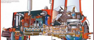
Transfer case control drive for ZIL-131 car
1 — gear shift lever; 2 - electro-pneumatic valve; 3 — breather tube; 4 — transfer case; 5 — air supply hose to the air-diaphragm chamber; 6 — traction fork; 7 — air-diaphragm chamber; 8 - lock nut; 9 — front axle drive shaft flange; 10 - longitudinal beam; 11 — transfer case mounting bolt; 12 — first gear engagement rod; 13 — second gear engagement rod; 14 — air supply tube to the electro-pneumatic valve; 15 — first gear engagement rod; 16 — second gear engagement rod; 17 — tension spring; 18 — gearbox; 19 — lever earring.
The system is distinguished by the presence of mechanical drives that are responsible for turning it on and off. There is a lever mechanism that is activated inside the driver's cabin using the clutch pedal.
Obtaining the required power indicators is ensured by transmitting energy in the direction of the transfer case due to the presence of a gearbox in the transmission, through the driveshaft. There is a term “handouts” in accordance with professional slang.
Possible gearbox breakdowns
It is possible to determine whether the gearbox is broken or not by the characteristic sounds. Signs of trouble:
- the occurrence of loud noise;
- spontaneous activation of gears;
- oil leak.
If there is strong noise from the transfer case, it is advisable to check the condition of the gears and bearings. These elements must be replaced. When the teeth wear out, the driver may encounter problems such as spontaneous gear shifting. You need to pay attention to the condition of the sealing elements. With prolonged use of the vehicle, they quickly lose their working properties. This is the reason why fluid will leak. The membrane in the pneumatic chamber and fastenings must be checked.
Operating principle and design of the transfer case
Torque comes from the gearbox, which is converted and transmitted further by the gearbox. It eventually reaches the wheels and axles located at the rear of trucks. The front-wheel drive is activated automatically or manually. The transfer case supports a low gear, the coefficient of which is 2.08. The relevance of the solution increases in the presence of the following difficult conditions for movement:
All this leads to an increase in torque by at least 2 times. It is transmitted by the transfer case to the wheel drives. Thanks to this approach, the motor does not begin to overheat, which ensures the absence of premature failure of the units.
Transfer cases are characterized by a two-shaft type, helical gears. The basis for the transfer case is a body cast on a cast iron base. The cover at the back and front also complements the overall design.
A PTO is mounted on top of the transfer case plane - a power take-off box. From the car engine, power is transferred to other units with devices in the systems.
The following nuances highlight the appearance of the ZIL 131 transfer case:
The rear appearance also has a number of distinctive features:
Technical characteristics of the ZIL-442100 truck tractor
| Wheel formula | Weight | |
| 4x2 equipped truck tractor, kg | 5025 | |
| load Distribution on the road from curb weight through kgf, N (tires) | front wheels | 29250 (2925) |
| rear axle | 21000 (2100) | |
| Load on the fifth wheel coupling device, kgf | 6200 | |
| Total weight of the truck tractor, kg | 11450 | |
| Distribution of load on the road from the total weight through the tires, N (kgf) | front 34500 | wheels (3450) |
| rear axle | 80000 (Full) | |
| 8000 weight of towed semi-trailer, kg | 18175 | |
| weight of full road train, kg | 23500 | |
| Turning radius, m | 6,9 | |
| Maximum speed of road train, km/h | 85 | |
| Control fuel consumption for road trains V=60 km/h, l/100 km | 24,4* | |
| Fuel tank capacity, l | EX tires |
* - At 170-12.
Additional Information
The toothed wheel begins to move along the grooves as soon as first gear is activated. Then, with the help of an intermediate type shaft, engagement occurs between the structure and the cardan from the 1st mode in the gearbox. Torque moves through gears and other auxiliary parts due to the primary pulley. Then the gear ratio is 7.44.
When the corresponding function is turned on, the work becomes relevant for the teeth of the second gear gear. This occurs due to the clutch on the corresponding synchronizer.
The gear wheel of the intermediate type already partially functions together with the entire system. The result is the transmission of torque to the secondary elements, from the primary ones. The gear ratio itself reaches 4.1.
The third gear is activated when the influence of the synchronizing disk on the elements of the second ceases. The splines transmit the clutch, which is then connected to the corresponding elements in the gearbox. And here the torque goes to the auxiliary elements.
The start of fourth gear activates the corresponding synchronizer. The same applies to reverse gears, but the mechanisms work here in reverse order. Only the torque passes to the secondary elements through all six gears. This is how the ZIL 131 gearbox works; the car’s circuit diagram has hardly changed.
Standard equipment of truck tractor ZILV 442100
Single disk
- Clutch, friction, with peripheral location of pressure Diameter.
- driven disk springs 380V mm.
- Drive by pneumatic booster and hydraulic.
Transmission
- Nine-speed with rear planetary gearbox.
- Gearbox ratios:
- second - 9.65
- first - 6.33
- third - 4.50
- fourth - 3.33
- fifth – 2.70
- sixth – 1.90
- eighth – 1.35
- seventh – 1.00
- ninth - 0.81
- reverse - 6.77
- Synchronizers on II, VII, IV, V, VI, III, VIII, IX gears.
- Control of the gearbox by a rocker lever.
- The range control is automatic with a pneumatic drive.
- Power take-off from right kW to 22V hatch is allowed.
- h3>Drive axle
- Single stage, hypoid.
- Gear differential, bevel with four cardan shafts.
Gear number - 5.29.
satellite transmission
- Two cardan shafts with three hinges, an intermediate support and a splined connection.
- needle bearings on hinges.
Wheels and tires ZIL-Wheels
- 442100 disk, 7.0 - 20.
- Tires are radial, tube, steering.
260R508 control
- Steering mechanism with hydraulic working.
- steam amplifier - a screw with a nut on the circulating gear.
- the number in the balls is 20.
Brake system
- Drum-type brake mechanisms with two internal shoes and an expansion cam, installed on all wheels.
- Parking brake system with spring energy accumulators on the rear axle.
- pneumatic brake drive, separate for the brake mechanisms of the rear and front axles, on the latter - automatic regulation of the braking forces.
Electrical system
- Single-wire, with a nominal Starter 12V.
- voltage 24V, with electromagnetic traction relay and remote control.
- Two rechargeable batteries, voltage 12V.
- AC current generator with built-in rectifier.
Cabin of truck tractor ZILV 442100
- Three-seater, two-door.
- The driver's seat is separate and has a suspension mechanism with adjustable rigidity depending on the driver's weight. In addition, the position in the longitudinal direction is adjustable, as well as the backrest tilt and cushions.
- Passenger seat double Windshield wiper.
- unregulated three-brush with electric drive.
- Windshield washer pump with electric drive.
Fifth wheel Additional
page This doesn't exist
5. New ZIL gearbox
- 4972 supplied directly from the manufacturer's factory. We buy a large number of new boxes at once and keep the cost minimal for the end buyer.
boxes Cost (manual transmission):
| Transmission options (manual transmission) | Gearbox Price | Buy |
| Used manual transmission ZIL 30000 | from 4972 rub. | |
| Gearbox ZIL bulkhead with 4972 | from 42,000 rub. | |
| Gearbox 4972 ZIL from overhaul | from 45,000 rub. |
Find out the gearbox for the price of ZIL 4972:
Phone: 8 (812) multichannel-02-10
B (701, 10.00-20.00)
Whatsapp (hours only! Chat from 10 to 20, closed on Sundays)
Viber: +7 (911) only-42-33 (766 chat! From 10 to 20 hours, Sunday - closed)
days of the gearbox depends on whether it is new, used, refurbished or repaired, as well as on our availability in stock or delivery time to our store.
Gearbox warranty
- from 30 days, depending on the condition of the box.
In the 70s of the 20th century, the USSR needed to create 2 types of trucks that would have different carrying capacities.
A necessary condition was the presence of a diesel engine. The production of one type of car belonged to ZiL, and the second - to Initial. KAMAZ developed both types of vehicles within the walls of ZiL. Later, all the technical documentation for the KAMAZ vehicle was transferred to the Embankment Collective.
The achievement of technology and science at that time was the V-shaped diesel engine, which had 8 cylinders. The power of this engine was 185 horsepower. locked Engine with nine-speed gearbox. The hood, radiator and fender trim are interconnected with the aim of being hinged forward.
This is made convenient for car maintenance. The comfortable cabin is equipped with a comfortable seat that can be adjusted in three directions. The car is equipped with an all-metal cargo carrying capacity. machine platform 6 tons.
Drive shaft repair
The specified part of the ZIL-130 gearbox is assembled on the table. In this case, the thread should point down. Lubricant is applied to the splines. Next, the first speed gear is installed, the hub groove is directed towards the front part of the input shaft. The correctness of the assembly is determined by checking the presence of its free movement along the splined elements.
Lubricant is also applied to the journal, the second speed gear is mounted, and the ring gear is turned toward the front edge of the secondary pulley. Solid oil is used to treat the thrust washer, which is placed in a seat with a locking ring. The gap between the side of the hub and the specified part should not exceed 0.1 mm. When installed correctly, the gear will rotate freely by hand.