At first I made a version like everyone else - based on a hydraulic jack - the collective farm is poor, and besides, the Chinese jack leaked the first time it was used.
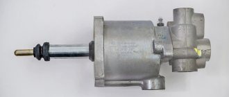
There, a man built a press from spare parts from a MAZ truck. The advantages of this approach: - the MAZ cabin pump is used as a pump - the maximum operating pressure is 25 MPa, there is a safety valve that can be adjusted - shut off or set to a lower pressure. The pump has a reversible inlet and outlet, which allows the installation to change the direction of oil supply, so that in the working cylinder it is possible not only to lower the rod, but also to raise it!
Maximum pressure developed by the pump, MPa: 25 Plunger diameter, mm: 16 Working volume, cm3: 8 Filling volume, cm3: 300 Response pressure of the safety valve in the filler plug, MPa: 2 Force on the handle at a distance of 600 mm from the longitudinal axis of the drive shaft , no more, N: 350 Weight, kg: 4.6
— The power cylinder power steering Maz TsG 80-280 is used as a working cylinder - a good product with thick walls, real metal, unlike a Chinese jack. It is designed for a nominal pressure of 10 MPa, but can also withstand long-term overloads (naturally, since it is installed in the steering wheel of a heavy truck). There is a thread at the end of the rod; adapters can be machined for different needs - metal bending, pressing, drawing, etc. Double acting cylinder.
Working pressure, no more, MPa: 10 Working diameter of the cylinder, mm: 80 Rod diameter, mm: 28 Full stroke of the rod, mm: 280 Weight, no more, kg: 13.5
— the connection is made with original MAZ copper tubes — for flaring you can buy a kit, which is also used for flaring car brake pipes. Although initially the tubes on sale are flared.
— It was necessary to machine an adapter to connect the pump to the power steering cylinder, because initially on MAZ it was connected to the cab lift cylinder, which is smaller and has a piston diameter of only 40 mm, not 80, and is not suitable for the needs of the press. Although it will be suitable for something else! I have attached a drawing of the fitting.
What pressure can such a device produce?
F = P*S = P*(pi*r^2)= 25,000,000 * (0.04 * 0.04 * 3.14) = 125600 Newtons, that is, the maximum force will be 12.5 tons of force
But this is an honest 12.5 tons of force, and not the Chinese 25, 30, etc. By the way, I initially wanted to buy a press, but I looked at all this crap that sells for crazy money (from 15 to 40 thousand rubles) and changed my mind - it was made poorly, for example, a matrix press based on a jack - even the jack handle is not cut off, others made not from a channel, but from thin sheet metal, this does not increase strength, but reduces weight, which is important when delivering goods - essentially logistics. In general, this is a dangerous tool for health. If this crap flies in front of your face, it won't seem like much.
I used channel 14 and 16 as metal - a real hot roller channel, not a bent one. I welded it wherever possible, the braces on the upper platform were additionally welded and also secured with German high-strength bolts with index 12.0. In order for the lower platform to be able to move the channel, it was given for milling - because 22 mm fingers connecting the tracks on tractors are used as locking pins. These fingers are made of a special alloy that will not let you down either.
I haven't installed the pressure gauge yet. Otherwise, the press is similar to the design with a jack. The hydraulic cylinder was secured with a native MAZ finger through a native ShS. You can mount the hydraulic cylinder higher, but I needed exactly this height of the final product, because... the press will stand on the street under a special canopy (a platform under the stairs of a private house) - in general, there were height restrictions.
The hydraulic cylinder and pump were disassembled, washed and rebuilt - there are repair kits for them on sale. I think after such an overhaul in the press they will work for a very long time without problems.
There was only one difficulty when testing the device. The pump would be designed for the volume of the cabin lift cylinder, and not for the volume of the steering cylinder, so its buffer capacity was not enough to accommodate the oil displaced by the cylinder when the rod was raised, and subsequently because If the oil that did not fit was poured out, then there was not enough oil for the subsequent lowering of the rod. It was not difficult to increase the capacity of the pump by welding a piece of threaded pipe onto its cover - now everything is ok. For some reason, the person from whom I took the idea did not encounter a similar problem, or simply did not try to drive the rod from stop to stop.
It’s a mystery to everyone - why, when the rod is lifted, more oil comes out of the cylinder than is sucked in? The pump and cylinder are double-sided! The answer is very simple!
The press easily coped with the task of repressing the silent blocks of the front and rear arms of the Grand Vitara!
Costs - repair kits for the pump and cylinder - 300 rubles. — MAZ copper tubes — 500 rub. — cylinder and pump — 2 thousand — removed the used one. from a truck that was going to be scrapped - a channel - lying in the yard, you can buy - it won’t be expensive - several thousand rubles. - work and experience - priceless - services of a turner and milling machine - on average, thanks or a couple of bubbles, depending on the desire of the performer, maybe 500 rubles.
Everything turned out to be much simpler than it seemed, now there is a convenient and reliable tool that will not let you down, is repairable, has accurate parameters, not inflated Chinese ones, and has been tested in operation.
Operating principle of the mechanism
The heavy weight of the cabin of modern KamAZ trucks makes manual lifting difficult. Therefore, it is equipped with a hydraulic mechanism. This allows you to lift and lower without using much physical effort.
REFERENCE: The hydraulic lifting system in some modifications of trucks is used to lower the spare wheel located behind the cab.
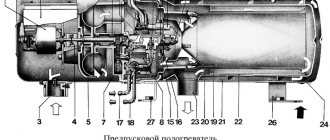
The tipping mechanism consists of several components:
- Double-sided hydraulic cylinder. The direction of movement of the hydraulic cylinder working rod depends on which input the oil pressure is applied to;
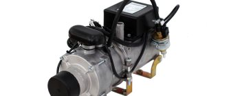
- Manual pump for lifting the KamAZ cab. Necessary for pumping oil into the system;
- High pressure hoses or metal pipelines.
Using a hydraulic pump, oil from the reservoir is supplied under pressure to the hydraulic cylinder. On older models, the oil tank is installed separately. Modern KamAZ trucks have a reservoir in the same housing with a plunger pump.
Oil pressure forces the cylinder rod out of the cylinder. The rod eye is pivotally connected to the cabin. When extending, the rod raises the cabin. For lowering, the pressure supply is switched to the second input of the hydraulic cylinder using a switch mounted on the pump. After switching, the pressure acts on the rod in the opposite direction. This leads to subsidence.
ATTENTION: Raising the cab of a KamAZ truck is possible until it reaches an angle of 41° relative to the frame. With additional manipulations, you can raise the cabin to 61o.
The heavy load on the hydraulic cylinder is reduced using a specialized balancing system. It allows for smooth lifting and lowering. The system is made in the form of two torsion bars. Their work is aimed at mutual opposition. Torsion bars are installed on the frame side members, and are attached to the cab on both sides. When the cabin moves, one torsion bar twists and the second one unwinds. This allows you to achieve balance at any angle of inclination. You can also read about Where is the KAMAZ oil pressure sensor located.
Model 65115
The instructions listed above will help you learn how to raise the cab on the KamAZ-65115 dump truck model correctly. But you need to take into account that in addition to the lowering and raising mechanism, there is also a balancing system. It simplifies the tipping process and does not allow the car to fall on its side when setting up.
It may happen that the force when raising or lowering the cab is too great. Then you can adjust the angle of twist of the torsion bar. The torsion bars are released from the load, raising the cabin. To increase the angle of twist, the axes of the lever supports are moved to the lower holes from the upper ones.
Design and operating principle of a hand pump
The KamAZ cab lift pump, the design of which is shown below, may differ depending on the modification of the vehicle.
The pump consists of the following components:
- Inlet valve. Made in the form of a ball installed inside a tube. When oil is sucked in, the ball rises above the seat, allowing liquid to pass through;
- Exhaust valve. It consists of a ball pressed to the seat by a spring. The valve opens when the required pressure is reached;
- Piston section. It consists of a cylinder in which a piston moves, connected to a drive handle. The piston is equipped with a rubber seal. This prevents oil leakage from the pump;
- Oil container. The oil tank is made in the same housing as the pump or is attached to it. It is connected to the piston section through the inlet valve;
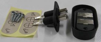
- Spool. Necessary to control the system when turning the handle to a certain position. The spool directs oil pressure to the required input of the hydraulic cylinder;
- Handle for driving the piston section. The pumps are equipped with a handle connected to a piston and fixed to the device body.
IMPORTANT: To reduce physical effort when working with the KamAZ cab lift pump, a lever is installed in the handle.
conclusions
To learn how to perform any actions with the cab of a KamAZ truck, it is enough to know the model of the truck. You can follow the standard instructions, since there are no special differences on most cars of the Russian automaker. A pump attached to the frame is responsible for lowering and lifting. Levers are used for adjustment. In order for the hydraulic mechanism to work properly, it is important to monitor the oil level.
The working fluid must reach the marks on the dipstick. To gain access to the engine, simply turn the handle. Depending on the model, the desired position is indicated as “raise” or indicated by an up arrow. Before lifting the cabin, you need to make sure that there are no loose objects in it, put the machine on the brake, thus preventing it from moving during manipulations.
The cabin of the car is all-metal, designed for two or three people. It has considerable weight, so any attempts to change its position in space must take all safety measures, as well as check the serviceability of the equipment.
Pump operating principle
When the plunger pump handle moves upward, the piston rises along the tube. Under the influence of vacuum, oil enters the piston section, lifting the intake valve ball. When the handle moves down, the piston presses on the oil located in the piston section. Under oil pressure, the intake valve ball is pressed against the seat and disconnects the channel connecting the section to the oil tank.
After closing the inlet valve, the pressure in the piston section of the KamAZ cab pump increases. When the required value is reached, the pressure compresses the exhaust valve spring. The exhaust valve ball comes off the seat and releases oil under pressure into the pipeline leading to the hydraulic cylinder. Thus, the rhythmic movement of the handle up and down allows you to pump oil pressure into the hydraulic cylinder.
Types of pumps and their applications
On trucks of the Kama Automobile Plant, regardless of modification. plunger type pumps are installed. They are distinguished by their reliability and unpretentiousness to ambient temperature.
The pumps of the KamAZ cab tilting mechanism are manually driven. This allows you to rollover when the power plant is not working.
All pumps are divided into two types:
- Single-circuit. Used only for the mechanism for raising and lowering the cabin. They are equipped with one spool that distributes oil pressure in the system;
- Dual-circuit. Used on vehicles with a spare wheel located behind the cab. They have two spools and two control handles. The operating principle of both spool valves is identical.
ATTENTION: The Kama Automobile Plant equips trucks with pumps from two manufacturers:
- PRT – made in Serbia;
- BAGU – produced in the Republic of Belarus.
Devices from different manufacturers have different mountings, technical characteristics, and are not interchangeable. This should be taken into account when selecting a replacement pump.
From the above it follows that the pump of the KamAZ cab tilting system is used to pump oil pressure into the hydraulic cylinder. Together with the balancing mechanism, the hydraulic cylinder smoothly raises the cab until it reaches the required angle relative to the truck frame.
KAMAZ vehicles are equipped with a tilting cab, the raising and lowering of which is carried out using a special mechanism with a hydraulic drive from a separate pump. Read about the pump for the cab tilting mechanism, its types, design, operation and maintenance in this article.
Cabin lifting methods
In fact, there is only one way to raise the cab of a KamAZ dump truck. In this case, the capsizing occurs forcibly. Unlike the platform, the cabin will not lower under its own weight. An installation powered by a plunger pump is used. It is also equipped with a tank with working fluid, a hydraulic cylinder and pipelines. The operation of the mechanism must be controlled manually.
There is a hydraulic cylinder under the front part of the KamAZ cab. If there is a problem with it, all planned actions will be difficult. A pump with a handle is attached to the rear suspension, which is used for control. When using the installation, oil is pumped into the hydraulic cylinder, which serves as a working fluid. When a person turns the handle, the rod moves in two possible directions: up or down. In accordance with the selected position of the handle, the cabin tilts or returns to its original position.
The device of the cab tilting mechanism (MCT) KAMAZ
KAMAZ trucks have a cabover layout, which, despite all its advantages, has one drawback - the engine is installed on a frame under the cab, and the cab has to be lifted to access it. Therefore, in trucks with a cabover layout, including KAMAZs, a special cab tilting mechanism (MCT) is used. Thanks to the presence of this mechanism, the cabin can be easily raised (overturned), which provides access to the power unit, clutch and other mechanisms located in the front of the frame.
Types and applicability of MOK hydraulic pumps
Today, manual plunger-type pumps are used in cab tilting mechanisms of Kama trucks (the same ones are used in hydraulic jacks). Regardless of the model, all plunger pumps are designed the same; the design of the pump is described below.
There are two main types of pumps used in Kama plant trucks:
• Cab tilting mechanism pump; • Cab tilt and spare wheel lift pump.
In the first case, the pump is designed most simply, and it is always connected only to the circuit of the cab tilting mechanism. The second type of pump provides the ability to switch between the MOC and spare wheel hydraulic lift circuits. That is, one pump can operate in two systems, which makes the car cheaper, and its maintenance and operation easier. Let us remind you that in a number of KAMAZ vehicle models (for example, KAMAZ-4310), the spare wheel is installed behind the cab on a special hydraulic lift - this facilitates the process of removing and storing the wheel, which has a fairly large mass and dimensions.
Currently, several models of pumps from two main manufacturers are installed on KAMAZ vehicles:
• Pumps Prva Petoletka (PPT), Serbia; • Pumps of JSC Borisovsky (BAGU), Republic of Belarus.
Pumps from different manufacturers have different characteristics, differ in installation dimensions and other parameters, which must be taken into account when purchasing a new pump.
But all pumps, regardless of model and applicability, have a fundamentally identical design.
Cabin tilt pump design
The pump is quite simple. Its basis is a housing in which a plunger pair is installed - a pressure plunger (piston) and its bushing. Under the plunger there is a channel that opens into the valve mechanism - a cavity with two balls, one of which (from the side of the discharge channel, the outlet) is pressed to its seat using a spring. The second ball (inlet) simply lies on its seat and can move freely along the channel.
A pump drive handle is installed on the housing above the plunger; it has a swinging support and is connected to the plunger through a simple hinge. Raising and lowering the handle ensures the movement of the plunger in the sleeve and operation of the pump. An oil tank is mounted on the side of the plunger pair housing to the pump, so the cab tilting mechanism does not have a separate tank. Inside the tank, a suction filter is attached to the inlet channel; there is also a safety valve that allows oil to drain from the discharge cavity back into the tank if the outlet valve is not opened.
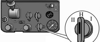
One of the main parts of the pump is the reversible spool, which is used to control the flow of working fluid in the MOK hydraulic system. The spool has two positions - “Raising the cabin” and “Lowering the cabin”; the position is selected by turning the spool using the handle provided for this. When the spool is turned to the “Cabin Raise” position, oil is pumped into a tube connected to the lower cavity of the hydraulic cylinder, and from the upper cavity oil flows through a nozzle into the tank. When the spool is turned to the “Cabin lowering” position, the oil supply is reversed - now it is supplied to the tube connected to the upper cavity of the hydraulic cylinder, and from the lower cavity the oil flows into the tank.
In pumps intended for installation in cars with a mechanism for raising and lowering the spare wheel, another spool is provided - with its help, the pump is connected either to the IOC hydraulic system or to the hydraulic system of the spare wheel hydraulic lift.
It should be noted that the device described above has PPT pumps - they are made in the form of a horizontal parallelepiped, in the upper part of which there is a handle. BAGU pumps and similar ones have a slightly different design: they do not have an oil tank as such, the role of a container for oil is played by the pump body itself, and the plunger pair is located inside the pump, directly in the oil. The valves and spool mechanisms of such a pump are located in its lower part. Externally, the pump is a vertically elongated parallelepiped, in the upper part of which, on one of the side walls, there is a plunger drive handle.
On the outer surface of the pump there are fittings for connecting to tubes, a plug for filling oil, and sometimes a plug with a dipstick for checking the oil level. Also, explanatory inscriptions or symbols must be placed next to the spool control handles.
Possible difficulties when lifting the cabin
As a rule, there are only two possible problems when lifting. With the first, the rise simply does not occur, and with the second, an incomplete rise is observed. In 99% of cases, the cause is a faulty pump. Possible problems and solutions:
- Incorrect connection of pump spools or hose ends requires reconnection of the tubes.
- Water getting into oil most often occurs in winter. Here, to solve it, you need to warm up the pump and change the oil.
- Pump leakage is most often caused by a loose rubber seal. In this case, the structural component requires replacement. It is also possible that there is an excess amount of oil inside the system. To fix the problem you will need a repair kit.
- The safety valve is jammed, which will need to be unscrewed and monitored to ensure that no oil fluid leaks out. The removed part must be washed, dried and adjusted to maintain a pressure of 15 to 17 MPa.
- If no working fluid is supplied, this indicates a breakdown in the suction valve. To check, you need to unscrew the plug and check the condition of the unit.
The lever rarely fails; this usually happens in case of careless operation. If the pump is in order and the handle does not jam, then the mechanism is working. Further adjustment is carried out according to the standard scheme.
How to operate the MOK pump
The KAMAZ vehicle cab can have three positions - transport (the cab is completely lowered), lifting at an angle of 41° and 61°. Lifting to both corners is done using a pump, but the procedure in both cases is slightly different.
To tilt the cab at an angle of 41°, do the following:
- Turn off the engine, brake the car with the parking brake, set the gearshift lever to neutral;
- Set the handles of both cab locks to the upper position;
- Disconnect the safety hook installed on the right cab lock;
- Move the reversing spool control handle to the “Cabin Raise” position (or to the up arrow - the designation depends on the pump model);
- Insert a mounting blade or other tool into the hole in the plunger drive handle;
- Rock the handle up and down to raise the cabin;
- After raising the cab, insert a safety pin into the hole in the limiter post (this will prevent accidental lowering of the cab).
To return the cab to the transport position, do the following:
- Remove the pin from the limiter post;
- Move the reversing spool control handle to the “Cabin lowering” position (or to the down arrow);
- By swinging the plunger drive handle, lower the cabin into the transport position;
- Secure the cab locks.
To raise the cab to the maximum possible angle of 61°, you must first remove the front bumper and open the hood (front panel), then perform the procedure described above. When the lift to an angle of 41° is reached, you need to remove the extension pin (after unscrewing it) and use a pump to raise the cabin. The cab is returned to the transport position in the reverse order, that is, first to an angle of 41°, and after installing the pin in the extension, to the transport position.
If the vehicle is equipped with a hydraulic spare wheel lift, then before tilting the cab or manipulating the spare wheel lift, it is necessary to set the spool handle on the pump to the position appropriate for the operation being performed. The raising and lowering of the hydraulic lift is also controlled using a reversible spool.