The steering column and driver's seat on the 4014M are located closer to the longitudinal axis of the 4014M compared to the 4014 for improved visibility. The hydraulic distributor is located in the front of the cab, and on the 4014 it is located to the right of the driver's seat. To improve access to the engine when servicing it, the hood is made of two doors, unlike the one-piece one on the 4014 forklifts.
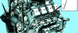
The engine is attached to the frame at four points via rubber mounts. The pressure reducing valve is located in the pump cover and protects the lubrication system from overload when starting a cold engine. The bypass valve is installed in the roof of the coarse filter and turns off the filter when the filter element is dirty (in this case, unfiltered oil enters the system). A safety valve is included in the oil cooler pipeline and stops oil circulation in the system when the pressure is less than 98 kPa. Engine crankcase ventilation is forced due to the vacuum created in the air cleaner and crankcase. The compression ratio of the combustible mixture of the GAZ-52-04 engine on 4014M forklifts is 7.2, on 4014 forklifts is 6.7, the fuel used is A-76 and A-72 gasoline, respectively.
The chassis transmission uses ready-made automotive units and a specially designed reverse mechanism. It is assembled in a separate crankcase. The MOX drive shaft rotates constantly when the engine is running; when the forklift moves forward, the driven shaft is driven directly from the drive shaft, and when moving back through an intermediate gear mounted on a roller bearing on a fixed axis. The forward or reverse lever must always be in one of the extreme positions. The manually operated parking brake is central and located between the gearbox and the MOX.
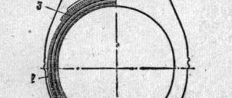
Rice. 2.2. Fastening the drive wheel hub to the axle shaft: 1 - axle shaft; 2 - hub; 3 - bolt puller; 4, 5 — studs for securing the axle shaft and wheel; 6 — brake drum; 7 — brake support disk; 8 — axle housing
The drive axle has a final drive containing a pair of helical bevel gears and a pair of spur gears, a differential and axle shafts. The differential box is detachable in two parts. The driven cylindrical gear of the main gear is rigidly connected to it. The differential box contains two bevel gears of the axle shafts and a spider with four satellites. The box rotates on two tapered roller bearings. The main gear drive cylindrical gear is integral with its shaft. The fastening of the drive wheels and hubs to the axle shafts is shown in Fig. 2.2.
The 4014M forklift is equipped with a hydrostatic (hydrostatic) steering mechanism XV-145-0/1 manufactured by NRB with a ZIL-130 steering column and an NSh 32U-2 hydraulic pump. The use of this mechanism makes it possible to reduce the force applied by the driver to the steering wheel when turning the car to 27.5 N. The main operating mode of the mechanism in question is the servo-boost mode, when it acts as a servo system. If the steered wheels of a forklift encounter an obstacle while turning, the pressure in the hydraulic system of the mechanism increases, the working fluid flows through the ball of the double safety valve to drain and normal pressure is automatically restored. If the hydraulic pump fails, the mechanism operates without servo assistance when the driver rotates the steering wheel.
During operation of the hydrostatic mechanism, the flow rate of the working fluid is constantly 12 l/min and is set by a special portioner-flow divider device. The safety valve of the portioner is adjusted to a pressure of 9.81 MPa. The steering hydraulic system is equipped with fine filters (model F1-20/25K, filtration fineness 0.025 mm) and coarse filters. The working fluid from the hydrostatic mechanism is supplied to the double-acting executive piston hydraulic cylinder of the steering. It is necessary that the steered wheels of the forklift be in the maximum rotated position for the shortest possible time, since in this case the cylinder piston occupies the extreme position and the working fluid quickly heats up. To remove air from the hydraulic system, the steering wheel is slowly turned several times from one end position to the other. The penetrated air is forced out into the oil tank and further into the environment. The presence of air in the hydraulic system is determined by uneven noise in the hydraulic units and if, when the steering wheel is rotated, the actuator hydraulic cylinder does not operate or its piston moves abnormally slowly, or if bubbles are noticeable in the oil tank.
The steering (Fig. 2.3) of the 4014 forklift contains a hydraulic booster from the Lvov production association “Avtogruzchik”. The globoidal worm of the ZIL-120 steering mechanism is pressed onto the lower end of the steering shaft. A three-ridge roller mated to the worm is fixed in the fork of the bipod shaft. The rotation of the worm causes the roller and bipod shaft to rotate, the bipod rod to move and the hydraulic booster to operate. The last end of the piston rod is connected through a ball joint to a console mounted on the chassis. The hydraulic booster combines an actuator cylinder and a spool-type control device. When oil is pumped to the left or right of the piston, the said cylinder moves relative to it. On the side opposite to the piston rod, a sleeve with through longitudinal slots is built into the spool body, communicating with each other by annular grooves in the body. A spool is placed inside the sleeve. It can move along the sleeve in both directions by 2.5 mm from the average neutral position, in which it is installed by a spring. The spool is connected by a rod, a spring and two nuts to the ball pin of the steering bipod 10. While no force is applied to the steering wheel by the driver, the spool is in a neutral position, and the pressure on both sides of the piston of the slave cylinder and the spool is balanced. When the driver turns the steering wheel, the bipod rod moves the spool. In this case, one cavity of the actuator cylinder is connected to the high pressure line, and the other to the drain. Accordingly, on one side of the piston the pressure increases, and on the opposite side it decreases, as a result of which the body of the power steering actuator cylinder 8 begins to move until the spool again returns to the neutral position when the driver stops rotating the steering wheel. When the actuator cylinder body moves by the same amount, the rod connecting the hydraulic booster with the intermediate steering lever moves by the same amount.
Rice. 2.3. Steering diagram: 1 - rear wheel; 2 — rear wheel mounting fist; 3, 6 — steering linkage rods; 4 — steering linkage lever; 5 — longitudinal thrust; 7 — intermediate lever; 8 — hydraulic booster; 9 — bipod thrust; 10 - bipod; 11 - worm; 12 — steering column
If the hydraulic booster is damaged or the 4014 is being towed by another vehicle with the engine not running, manual control without the hydraulic booster is possible. In this case, both cavities of the actuator cylinder communicate with each other through an emergency ball valve. The power steering safety valve prevents overload when pressure increases.
Drum-type service brakes are built into the front drive wheels. The drive is hydraulic. There is a device for automatic stabilization of the gap between the pads and drums. Brake fluid flows to the actuating wheel hydraulic cylinders from the main brake cylinder when the driver presses the pedal (Fig. 2.4): the pusher moves the piston to the right, the cuff closes compensation hole B, the pressure in the working cavity of the G cylinder increases, and the exhaust valve opens. As a result, the wheel hydraulic cylinders are activated and braking is performed. After the pedal is released, the spring moves the piston to the left, the pressure in the working cavity of the master cylinder decreases, the brake pads and pistons of the wheel cylinders return to their original position under the action of the tension springs. In this case, the brake fluid is forced out of the wheel cylinders into the main cylinder through the inlet valve. The reliability of the brakes of the 4014M forklift has been increased due to an increase in the drive gear ratio by 1.5 times and an improvement in the system for automatically adjusting the gaps between the drum and the shoes.
Rice. 2.4. Main cylinder of the hydraulic drive of the foot brake: 1 - reflector; 2 — filter mesh; 3 - cylinder body; 4 — return spring; 5 - piston; b - pusher; 7 — rubber cap; 8 - traction; 9 - pedal; 10 — filler cap; 11 — inlet valve; 12 — exhaust valve spring; 13 — exhaust valve; A, G - non-working and working planes of the cylinder; B, C - bypass and compensation holes
The parking (hand) brake on both models of forklifts uses a central brake acting on the transmission. The brake drum is screwed to a flange on the splined end of the driven shaft of the reverse mechanism. The brake pads are located inside the drum. The nature of the brake is borrowed from the ZIL-130 car (Fig. 2.5). The parking brake is regulated by reducing the gaps between the shoes and the drum, which have increased due to wear on the linings (detected by an increase in the free play of the lever), in the following sequence. The MOX lever is set to the neutral position. The rod is disconnected from the lever, after which it is moved to the extreme forward position. The length of the rod is changed by screwing a fork onto it so that the loader is braked completely when the pawl is moved using a 4-6 tooth sector rod attached to the frame of the machine. If the lever is moved to the extreme forward position, the brake drum should rotate freely without touching the pads. If braking is not achieved with the minimum length of the rod, it is necessary to move the pin securing the end of the rod to the next hole in the adjustment lever and re-set the desired length of the rod, securing it with a nut.
Rice. 2.5. Handbrake drive
Both forklift frames are welded. The lifting-lowering cylinder is installed on the lower link of the outer frame. Trunnions are welded to the outside of its racks for pivoting the load lifter to the chassis and two brackets connected with pins to the tilt cylinder rods. At the top of the racks there are two rollers that guide the movement of the inner frame. Two corners are welded to its upper transverse beam, along which the rollers of the traverse, attached to the top of the plunger of the lifting-lowering cylinder, move. When lifting the traverse within the guide angles, the internal frame remains motionless and the carriage is lifted freely without changing the height of the load lifter. Subsequently, the plunger interacts with the upper beam of the inner frame, and it also begins to rise. On the 4014M forklift, the design of the internal frame allows the replacement of worn guide rollers with new ones without disassembling the forklift.
Rice. 2.6. Carriage
The carriage (Fig. 2.6) is suspended on two plate chains that go around the blocks on the traverse of the lifting-lowering cylinder plunger and are fixed at the ends to a bracket welded to the cylinder and to the carriage. The chains have a screw tensioner. The carriage consists of lower and upper plates connected by racks 3. Four rollers 4 are installed on them, rolling on the shelves of the racks of the internal frame of the forklift, and four rollers moving along the walls of these racks and serving to transmit lateral forces to them. The roller axes are mounted in the axles of the carriage rollers.
For the hydraulic systems of the forklift and power steering, the oil tank is common (Fig. 2.7). While the engine is running, both hydraulic pumps are active, and when the hydraulic valve spools are in the neutral position and the steering wheel is in a stable position, oil flows freely into the tank. The forklift valve block consists of a check valve and a working fluid flow regulator. It is designed to securely hold a raised load. If the hose breaks or the forklift engine fails, in order to smoothly lower the load, it is necessary to break the check valve seal and carefully unscrew it with the hydraulic distributor handle that controls the lift-lower cylinder set to the neutral position. When lifting a load, the pressure of the working fluid presses the valve away from its seat, and the fluid enters the lifting and lowering cylinder. When the hydraulic valve spool controlling this cylinder is set to “lowering”, the working fluid is supplied under a command pressure of 1.57 - 1.77 MPa to the fluid flow regulator. Accordingly, the speed of the lowered load will be higher or lower.
Rice. 2.7. Diagram of the hydraulic system: I - three-spool hydraulic distributor; II — power steering; III - oil tank; IV — forklift valve block; 1 — power steering valves; 2 - pressure gauge; 3 - power steering pump; 4, 5 — locking devices” 6 — forklift system pump; 7 — lifting-lowering cylinder; 8 - filter in the drain line; 9 — tilt cylinders; 10 - rotary couplings for connecting hoses of replaceable working bodies; 11 - pressure spool
Rice. 2.8. Valve block of the lifting-lowering cylinder: 1 - housing; 2 — valve for regulating flow when lowering the load; 3 - spring; 4 - check valve; 5 — pulling device; 6 - spring; 7 - cap
The oil tank has two filters: in the filler neck and in the drain line from the hydraulic distributor. A bypass valve is installed in the housing of this filter under the inlet, through which oil can flow into the tank without filtration if the filter elements are clogged. The valve is adjusted to a pressure of 392 - 441 kPa. Normally, oil passes through the filter elements into the oil tank.
The drive of both hydraulic pumps is common and consists of a cardan transmission from the engine crankshaft and a single-stage reduction gearbox with cylindrical helical gears operating in an oil bath. Gear ratio 1.65.
The hydraulic distributor is a three-spool valve with safety and check valves. The spools are returned from the working position to the neutral position by springs. If all spool valves are in the neutral position, the working fluid from the pressure section enters the drain channels of the spool sections and then through the cavity of the drain cover into the oil tank. The check valve prevents the backflow of working fluid from the hydraulic cylinders through the pressure section and overflow channels when the spools are turned on and off.
The command pressure to open the working fluid flow regulator to lower the load (or gripper) is supplied by the throttle. Oil is supplied to the valve block on the lift-lower cylinder (Fig. 2.8) and then into the drain pipeline. When lifting the load, the oil through the fitting presses the check valve to the left and flows through the cavity of the valve block to the mentioned cylinder. The valve that regulates the oil flow is pressed against the seat by the pressure of the oil and the force of the spring, i.e., it is locked.
If the hydraulic valve spool controlling the lifting-lowering cylinder is in the neutral position, then the oil pressure in this cylinder from the action of the gravity of the load and the overhanging part of the forklift, together with the force of the spring, closes the check valve. At the same time, the flow control valve is also closed. After installing the hydraulic valve spool in the “Lowering” position, oil from it is supplied through the fitting into cavity A and moves the valve to the right.
The electrical circuit is conventional, single-wire (" - " connected to ground), like in cars.
The 4014D forklift is a modification of the 4014 model. It is distinguished by the use of a two-stroke diesel engine D144-07 as a power unit and a different transmission mechanism for the movement mechanism. The layout as a whole is the same as that of the base machine.
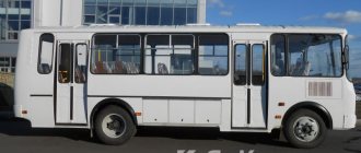
Lviv forklift AP-41030
Lifting and moving large, heavy loads at production, transit, transshipment and other facilities is carried out using special equipment called forklifts. They differ in drive type, load capacity and other features.
If we talk about the most common models that have found their application in many sectors of human activity in almost all countries of the post-Soviet space, then the Lviv 5-ton forklift deserves special attention. About what this type of special equipment is, what its features and advantages are, will be discussed in our conversation today.
Loader Operational Capabilities
The most important difference between the loading equipment and the Lviv plant is its stability, which is facilitated by a wide wheelbase and a carefully designed track of the driving wheels.
A low center of gravity plays an important role in achieving the required performance characteristics. It, among other things, provides the model with the ability to move even on bumpy or slippery surfaces.
Due to the fact that the design of the hydraulic cylinders responsible for lifting the carriage contains durable polymer seals, the loader can perform more than 90 thousand. lifting/lowering cycles without mandatory repairs and maintenance.
The undeniable advantage of the machine is that it can grab the processed load directly from the ground. The carriage is lowered and raised while the load receptor remains at the same level.
The safety of the operator during work, eliminating the risk of a load falling on him, is ensured by the reinforced frame of the cabin, which is convenient, comfortable, and characterized by a large viewing angle. Equipment controls are at hand. A soft driver's seat with shock absorbers helps minimize fatigue even during prolonged work.
Advantages and disadvantages, prices
It’s not for nothing that the AP-41030 forklift is in such high demand - it has a lot of advantages compared to many analogues:
- High reliability, stability, long service life.
- Excellent performance.
- Simplicity of design, guaranteeing excellent maintainability and ease of maintenance.
- More than 90 thousand lifting/lowering cycles without maintenance.
- Rollover protection, ability to move on any surface.
- High level of operator safety.
But this model also has certain disadvantages. First of all, this is the presence of harmful emissions, which is why the forklift cannot be used indoors. Another disadvantage is that acceleration is not smooth and efficient; the car accelerates jerkily.
As for the price, it is difficult to buy AP-41030 new in Russia. Due to the problems that the manufacturer has been experiencing in recent years, its dealer network is poorly developed. To place an order to purchase a machine directly from the assembly line, you must contact the company directly.
But as for used Lviv forklifts, there is no shortage of them on the market. Depending on the technical condition, the cost of equipment varies between 240-450 thousand rubles.
Technical characteristics of the special vehicle
Speaking about the characteristics of the Lviv forklift more specifically, it is important to mention the following parameters:
| Specifications | Values |
| Dimensions (L*W*H), m | 3,9 * 5,1 * 2,35 |
| Height (with forks lowered), m | 2,65 |
| Wheelbase, m | 3,4 |
| Track front/rear, m | 1,79 / 1,48 |
| Minimum distance between the road surface and the lift, m | 0,2 |
| Weight, t | 6,35 |
| Mass of cargo that the model can lift to a height of up to 3.3 meters, t | 5 |
| Mass of cargo lifted to a height of more than 3.3 meters, t | 4 |
| Frame tilt angle forward/backward, degrees | 3/12 |
| Minimum fork lifting speed, m/s | 0,45 |
General description of the loader
The key advantages of this type of special equipment are, as mentioned above, its stability even when loaded, high strength, maximum reliability, endurance, long service life and ease of maintenance. Having all the necessary parts and components readily available contributes to good maintainability.
The forklift, which is popularly dubbed the “Lion,” is characterized by a reinforced chassis, fairly high ground clearance, an improved cabin with a durable frame, as well as a powerful power plant that makes it possible to work in harsh conditions and allows you to transport heavy loads on less-than-ideal road surfaces. Practice shows that the car moves well off-road.
The model is equipped with a classic GAZ-52/53 4-speed manual transmission for this type of equipment, which provides it, firstly, with a more affordable price compared to foreign analogues, and secondly, eliminating the need to use hydraulic fluid, which is required for the operation of hydromechanical transmissions (this is what forklifts are most often equipped with).
There are no complex hydraulic transmissions here; torque is transmitted from the diesel engine to the drive wheels through a cardan drive. The main gear is double; its design includes cylindrical and bevel gears (2 pieces each) with spiral teeth.
However, a manual transmission also has disadvantages. They should be understood as the inability of the vehicle to accelerate smoothly, without shocks and vibrations. In defense of the system, it is worth mentioning its reliability and good maintainability.
Purpose of loader 41030
Despite the fact that the specialized market offers a huge amount of loading equipment, both domestic and imported, you should not immediately pay attention to expensive products from well-known Western manufacturers.
They are seriously competing with the machine that became the subject of our conversation. Its high demand is facilitated by its affordable cost and decent quality, the observance of which at the manufacturing plant, and this is the Avtonavantazhuvach enterprise (Lvov), is monitored especially carefully.
The Lviv forklift has found its application in the process of transporting various cargoes with a large specific gravity. Since the machine produces a large amount of harmful emissions during operation, they try not to use it in closed warehouses.
High stability and the presence of a closed operator cabin allow this model to be used in open areas, and the tasks can be performed in any weather conditions, including in the rain.
The excellent performance characteristics of the loader are surprisingly combined with the simplicity of its design. It ensures that in the event of any malfunction, the car can be repaired in a regular workshop, where freight transport is serviced.
This is really important, because in the vast majority of cases, loading equipment with complex hydraulics is not so easy to repair; this requires special equipment and personnel who have undergone appropriate training and have extensive experience.