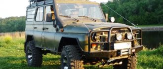
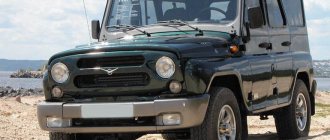
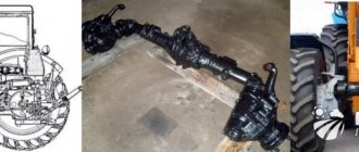
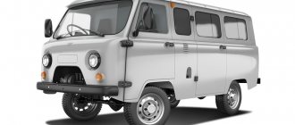
The UAZ Patriot and UAZ Hunter vehicles, as well as all models based on them, are equipped with front and rear single-stage Spicer-type drive axles with a one-piece crankcase, named after the American engineer Clarence Spicer
External view of the Spicer front axle
Spicer type bridges began to be installed on the UAZ-3160 and UAZ-3162 Simbir vehicles, instead of Timken-designed bridges. But these cars, like the first UAZ Hunter models, were equipped with “narrow” axles with a width of 1445 mm.
On the UAZ Patriot they began to install “wide” bridges with a track of 1600 mm.
Design features of Spicer bridges
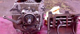
The axle housing consists of a one-piece cast main gear housing, axle shaft housings (stockings) pressed into it, and a stamped housing cover.
The absence of a connector in the transverse plane of the bridge gives the structure high rigidity, the unloaded connection between the cover and the crankcase reduces the likelihood of leakage at the joint, and the placement of the main gear and differential in a single crankcase ensures high precision of engagement and more favorable conditions for the operation of bearings.
Thanks to all these design features, the actual service life of bridges has increased significantly. In addition, now to access the main gear and differential there is no need to remove it and “halve it” - you just need to remove the cover.
To reduce warping of the driven gear during its heat treatment and, as a result, reduce noise, increase the reliability and durability of the main gear, the thickness of the “substrate” of the driven gear was increased by 8 mm. However, this measure led to a change in the left differential cup. But, the new differential can be used on previous single-stage axles with a split crankcase, provided that a compensator ring is installed on the cup stud.
Spicer bridges are unified with single-stage bridges of the old design in a number of other details. These are differential bearings, rear axle axle shafts and almost all parts of hub units. The front bearing with a double seal (469-2307086-03) and the new double-edge seal of the drive gear flange are unified with similar parts of U-shaped (“military”) axles produced by UAZ OJSC.
As for the front drive and steering axles, here, in addition to the above points, it should be noted the new constant velocity joints (CV joints) of the “Birfield” type, which are much more durable than the hinges of the old design (Weiss). Currently, all bridges of the Spicer and Timken types are equipped with such hinges. It would be worth recalling that to lubricate the Birfield hinges, a special CV joint grease is used, which must be placed not into the entire internal cavity of the steering knuckle, as before, but only into the hinge itself. The use of other types of lubricants, including the traditional Litol-24, is unacceptable. During operation, adding lubricant to the joint is not required. The internal cavity of the steering knuckle is still filled with Litol-24 lubricant.
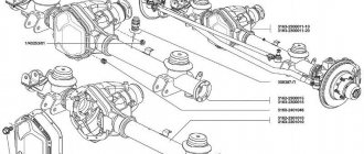
Main gear: 1 - bolt; 2, 33 — spring washers; 3 - driven gear; 4, 24 — axle shafts; 5 — adjusting ring; 6, 22 — bearings; 7 — spacer sleeve; 8 — outer race of the outer roller bearing; 9 — roller bearing; 10 — thrust ring; 11 — oil seal; 12 - reflector; 13- flange; 14 — washer; 15 — nut; 16 — axle housing; 17 — adjusting ring of the drive gear; 18 — outer race of the internal roller bearing; 19 — internal roller bearing; 20 — oil deflector ring; 21 — shaft with drive gear; 23 — adjusting nut of differential bearings; 25, 39 — right and left parts of the differential housing; 26 - bolt; 27, 40 - support washers for axle gears; 28, 43 — axle gears; 29, 45 — differential satellite axes; 30, 41, 44, 46 — differential satellites; 31, 38 — differential bearing covers; 32 — retainer for the differential bearing adjusting nut; 34, 36, 37 — bolts; 35 — main gear housing cover; 42 — final drive housing cover gasket
The ones produced have a gear ratio of 4.111 (37:9) or 4.625 (37:8). Axles with a gear ratio of 4.111 are installed mainly on cars with gasoline engines, and with a gear ratio of 4.625 - on cars with diesel engines.
Main pair adjustment
After repairing the front axle associated with replacing gears, it is necessary to adjust the contact patch:
- Select a spacer ring (parts are produced with a tolerance of 0.025 mm in both directions) that provides the required clearance in the tapered bearings of the drive shaft. When selecting, the distance between the center of the axle shaft and the lower edge of the spacer sleeve (parameter A) is taken into account. It is also necessary to take into account the gap between the edge of the inner ring and the opposite edge of the outer ring (parameter B). The thickness of the ring is determined by the formula C=A-(111.96+B).
- Place the ring in the seat.
- Insert the outer bearing races of the drive shaft into the crankcase.
- Place the oil drain ring onto the drive shaft, and then mount the rear bearing.
- Install the spacer sleeve and insert the shank into the crankcase.
- Place the 2nd bearing on the drive shaft, the ring is mounted until it stops.
- Install the washer on the spline part, and then put on the flange (used to connect the driveshaft).
- Secure the ring and flange with a nut, tighten the threaded connection until the axial play is eliminated. The shaft rotation force should not be higher than 2.0 N*m if new bearing supports are used. If old bearings are used, the torque value is 0.4-0.8 N*m. The tightening torque of the nut should be in the range from 180 to 250 N*m; when increased force is applied, the spacer sleeve is compressed.
- Apply marks to the surface of the flange and nut (for example, with oil paint or nitro enamel), which are used for further adjustment of the bridge.
- To mount the differential in the crankcase cavity, you need to purchase several sets of adjusting washers that differ in thickness.
- Install the original washer (which was used with the old gears), and then open the structure with the nut, which is located on the right side.
- Apply oil paint or other coloring material that does not dry for 30-40 minutes to the gear teeth.
Turn the gears 3-4 turns and inspect the imprint that appears on the drive gear. If the spot has an oval configuration and is located in the central part of the teeth, then the adjustment is correct. The shift of the spot towards the top of the tooth indicates the need for the shank to move closer to the differential gear, but at the same time the driven wheel is moved away from the drive gear.
If the spot is shifted to the base, then the drive wheel is moved away from the driven wheel (by reducing the thickness of the adjusting ring). To keep the side clearance within acceptable limits, it is necessary to move the driven gear towards the drive gear. When the spot moves to the narrow or wide end of the tooth, it is necessary to move or move the driven gear accordingly.
After the adjustment is completed, an oil seal is installed to prevent oil leakage. Then the shank bearings are tightened (until the paint marks align). To prevent spontaneous unscrewing of the threaded connection, the nut flange is jammed into a special groove provided on the side surface of the shaft.
Read: why install hubs on UAZ?
Drawing of the steering knuckle and hub
1 – leading flange with plug; 2, 10, 25 — gaskets; 3 — hub with brake disc; 4 — hub bearings; 5 — wheel mounting bolt; 6 — brake disc guard; 7 – heat-insulating shield of the ABS sensor; 8 - axle; 9 — steering knuckle body; 11 — clamping bushing; 12 — kingpin; 13 — king pin insert; 14-bracket for fastening the ABS harness; 15 - spring; 16 - outer sealing ring; 17 — internal sealing ring; 18 — hinge; 19 — ball joint; 20, 28 - thrust washers; 21 – kingpin support; 22 - outer race of the oil seal; 23 — overlay; 24 - nut; 26 – impulse disk; 27- cuff; 29 — retaining rings; 30 - lock washer; 31 - nuts; 32 — lock washer
Removal and installation of the final drive of the rear axle UAZ Patriot 3163
The front axle is equipped with a monolithic cast gearbox housing (Spicer design), in which axle shaft stockings are installed. Due to the absence of a parting line, the rigidity of the structure is increased and the operating conditions of the gears are improved. A cover secured with bolts is used to access the gearbox and differential. The internal volume of the crankcase is used to store a supply of lubricant; drain and inspection holes with plugs are provided. The tension-mounted stockings are intended for installing the beam on the frame and for mounting the front wheel drive axle shafts.
Front axle Spicer camber, toe-in
The front axle is a steered axle. To make driving easier, the front steered wheels have camber (not adjustable) in the vertical plane and toe in the horizontal plane.
Wheel alignment. A < B by 1.5-3 mm.
To return the wheels to the middle position, the steering knuckle pins are tilted in the longitudinal and transverse planes.
Positive camber is the deviation of the upper part of the wheel from the vertical plane outward. The camber angle of Spicer bridges is a = 1 – 30′. Wheel camber affects tire wear. With a camber of up to 2, wear will not be very large. During vehicle operation, due to wear of the pins, bearings and fatigue wear of the bridge beam, positive camber gradually decreases to zero, and then the deflection of the wheels moves towards negative camber, which worsens the steering of the wheels.
As a result of the tilt of the wheels during camber, forces arise that tend to return them in different directions when moving. Lateral wheel slippage occurs, which contributes to tire wear and makes driving difficult. To eliminate the harmful effects of camber, wheels are installed with toe-in. At the same time, the distance between the wheel rims at the level of the front axle in the front is several millimeters less than in the rear.
The longitudinal tilt of the kingpin (KASTOR) is designed to stabilize the steered wheels in the middle position, but its effect is noticeable only at high speeds with significant centrifugal forces. Measurements of wheel stabilization when the car exits a turn are the stabilizing moment and the angular speed of rotation of the wheel when returning to the neutral position.
Why is adjustment needed?
Adjusting the device on a UAZ Patriot SUV is necessary for:
- improving vehicle handling and stability;
- reducing fuel consumption;
- reduction or disappearance of extraneous sounds produced by the device.
The differential has two component areas:
- rings located outside, which are pressed into the bridge;
- inner rings that are pressed onto the unit.
The device with rings is separated using special shims. Of course, adjusting the front device is not an easy process, but if you have the will, anything is possible. Thus, knowing why differential adjustment is needed, let’s proceed to the actual process.
Features of setting up the front gearbox
Spicer Bridge Maintenance
Maintenance of the Spicer axle comes down to maintaining the oil level in the crankcase and periodically replacing it, monitoring the condition of all seals and fastenings of the axle and timely elimination of any axial clearances that arise in the gear and differential bearings.
The maintenance and repair operations for Spicer bridges are described in detail in the Maintenance and Repair Manual for the UAZPatriot IR-05808600.050-2005. Third edition. 2007
See also:
- UAZ drive axles with final drives
- Front axle of UAZ cars
- Rear axle of UAZ cars
- Description of UAZ civil bridges
- Description of UAZ military bridges
Possible faults
Constant increased noise when the front axle is operating. 1
.
Worn or incorrectly adjusted differential bearings. 2
.
Incorrect adjustment. damage or wear of gears or bearings of the gearbox. 3
.
Insufficient amount of oil in the axle housing. 1.1
.
Replace worn parts, adjust differential bearing. 2.2
.
Determine the gearbox malfunction, repair or replace it. 3.3
.
Restore the oil level, check for oil leakage through the front axle crankcase seals. Noise during vehicle acceleration and engine braking 1
.
Incorrect adjustment of the main gear gear engagement. 2
.
Incorrect side clearance in the meshing of the final drive gears. 3
.
Increased clearance in the drive gear bearings due to a loose flange nut or worn bearings. 1.1
.
Adjust the engagement. 2.2
.
Adjust the gap. 3.3
.
Adjust the clearance and replace the bearings if necessary. Knock when the car starts moving 1
.
Wear of the hole for the pinion axle in the differential box 1.1
. Replace the differential box and, if necessary, the pinion shaft.
What is a locking differential?
Structurally, the differential, equipped with a lock, is designed in exactly the same way as the standard open-type units, but in this case, a mechanism is added to limit the difference in the speed of rotation of a pair of output gears. This mechanism can be pneumatic, hydraulic or electric.
The electric differential lock of the UAZ, in which the locking is fully automatic or at the press of a button, has become the most popular recently. The driver can decide when it is best to disengage the differential to take full advantage of the uniform rotation of the wheels.
Blocking options
Depending on the characteristics of the machine, different operation limitation schemes are used - manual or automatic.
When the wheels of a car completely ignore the force of traction on the road, equal force will be transmitted to them from the engine. In this regard, it makes the vehicle's cross-country ability more efficient, no. This is possible when the vehicle is equipped with an open differential. Therefore, it is not surprising that recently it has become common to use the differential lock of the UAZ military axle and other options to increase the cross-country ability of this vehicle.
What is it like?
There are three main categories to note:
- Open;
- closed;
- limited slip differential.
Depending on what type of design is taken into account, the nature of the technology for transmitting forces to the wheels also changes. If one wheel loses traction, the transmission transfers all the torque to that axle and the wheel that has lost traction begins to slip. It is then that it becomes necessary to lock the differential on the UAZ in order to temporarily turn off the unit and evenly distribute the torque between the axles. Therefore, in some situations, blocking provides much better maneuverability.
When is it needed?
Not everyone knows that in real operating conditions, wheels can rotate at different speeds in different situations, namely:
- When turning, the outer wheel must move an order of magnitude more than the inner wheel.
- In uneven road conditions when both wheels are traveling on different terrain.
All of the above features are not very relevant for drive shafts since they are not actually connected to each other and rotate completely independently. However, the driven pair receives power directly from the gearbox, and each wheel is rigidly connected to the gearbox, making cornering difficult.
Where to install?
In any case, the UAZ center differential lock is a useful device that you can install yourself, even if the design of your car did not initially provide for this. In the vast majority of cases, Experts recommend installing it in the rear of the car, since a correctly installed lock allows you to equalize traction between the rear and front wheels. This solution is much safer and more effective. If we talk about the features of installation work, then in themselves they are not particularly difficult, and if necessary, they can be carried out both in a standard inspection channel and on a lift.