- home
- Media center
- Articles
- Tire pressure ZIL 130, ZIL 131
Menu
- News
- Articles
- Video materials
- Photo materials
- Publication in the media
- 3D tour
15.12.2020
Before leaving for a new trip, every truck driver must check the tire pressure on ZIL 130, 131, 4331 and other modifications. This is an important indicator, since under load certain difficulties and emergency situations may arise. Sometimes you have to pump up and down more to overcome dangerous areas in winter. Many ZIL trucks, including those, have an automatic inflation system that maintains this indicator in all wheels at a given value.
Operating tires with low pressure leads to rapid wear and overheating. The optimal value of air pressure in the wheels is 3.% for the front wheels and 4.3-5 for the rear wheels. In particular, the tire pressure on a ZIL 130 dump truck should be 4.3 bar. For modifications ZIL-130G, ZIL-ShV1 and ZIL-130, the optimal pressure value is a reading of 5 bar.
Tire pressure zil 130 dump truck
ADJUSTING AIR PRESSURE IN TIRES OF ZIL-130, 131 CARS
Before each vehicle departure on the line or on flights, you should check the air pressure in the tires and if there are deviations from normal pressure, you need to adjust it (if the pressure decreases, pump it up, and if it increases, deflate it).
Driving a vehicle with tire pressure reduced or increased against the norm is unacceptable, since in both cases it leads to a sharp reduction in tire service life. Operation at low air pressure has a particularly negative effect on tires, and in addition, fuel consumption increases due to increased rolling resistance of the wheels.
Adjusting the air pressure in the tires of the ZIL-130 car. The air pressure in the tires of a ZIL-130 car should be checked only with a tire pressure gauge. In this case, the deviation from the established pressure standards in one direction or the other should not exceed 0.2 kg/cm2.
When inflating tires, the air pressure in the pneumatic brake system must be at least 5-6 kg/cm2. If there is no such pressure in the system, you need to start the engine and raise the required air pressure.
The procedure for inflating car tires should be as follows: unscrew the wing cap from the air bleed valve on the air cylinder and screw the connecting nut of the tire inflation hose onto the valve; open the tap, unscrew the cap from the chamber valve and attach the tip to the valve.
After inflating the tires, disconnect the hose from the valve and check the pressure in the tire chamber with the pressure gauge included in the tool kit. The air pressure in tires of wheels of size 260 - 20 for the ZIL-130 car and its modifications is given in table. 10.
The legendary truck that began its life under the USSR is ZIL. The plant produced trucks to meet all the requirements that could arise: truck cranes, truck tractors, refrigerators, vans and a huge number of other varieties. ZIL is known not only for its trucks and government cars - Kamaz began its journey at ZIL factories. Now only a few people remember this, but it was at ZIL that Kamaz received its first versions of cars that formed the basis of the modern automotive industry. But, like any car, trucks require high-quality tires to move and deliver goods.
Replacement
To replace standard ZIL wheels, the following options, which have proven themselves only on the positive side, are ideal:
- Omskshina N142B-1 is an ideal ZIL-130 tire. All-season tires that meet all modern requirements for reliability in cargo transportation. They performed well on trucks and are therefore one of the most popular on the market.
- Kama 218 – tires for light trucks (ZIL Bychok). Excellent directional stability, low price and excellent handling - what else is required from good tires?
- ForwardTraction is one of the best tires for ZIL-4331. Provides excellent grip on the road surface and high directional stability and gives the car excellent driving characteristics.
- M-93 is a tire that has proven itself only from the best side. The dimensions are ideal for the ZIL-131, and the driving characteristics fully meet the requirements of this vehicle. The unique tread pattern gives the tire high cross-country ability and makes the rubber one of the best on the market.
- ALTAISHINA ID-304 is another tire for 131. Low cost and excellent characteristics make this tire a worthy competitor among analogues. Despite the fact that the tread pattern is universal, it gives the car high directional stability and resistance to aquaplaning.
The bottom line can be summed up as follows: in order for the legendary truck to continue to drive and perform its direct functions, its condition needs to be monitored, and one of the main elements that need constant monitoring is the tires. If you take proper care of your tires, your car will repay it with a long service life and will get you anywhere you need to go!
Characteristics
A huge selection of additional equipment was offered for ZIL trucks, which made the vehicle universal for all areas of operation. The machine could be used to transport goods, and the version with a crane could be used for construction and utility purposes.
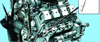
The truck was equipped with a 6.0 liter V-shaped engine with 8 cylinders and a two-chamber carburetor. Output power of 150 hp. it was enough for a load capacity of 6 tons, and it allowed it to confidently perform the functions of a medium-tonnage truck.
Further modifications of the truck were produced with a modified version of the ZIL-130 engine. Most improvements consisted of adapting the motor to various conditions (faster acceleration, greater load capacity, etc.).
How to disassemble a wheel on a ZIL-131
The vehicle is equipped with interchangeable disc wheels with the wheel rim size ZIL 131 - 228G508, with cut bead rings. Tire size for ZIL-131 is 12.00R20 or 12.00-20 (for radial and diagonal cords, respectively). That is, the wheel diameter for ZIL-131 is 20 inches.
When disassembling manually, you must perform the following operations:
- Remove the wheel from the car.
- Deflate all the air from the tire and place the wheel on a flat horizontal area with the rim locking part facing down.
- Remove the inner bead of the tire from the rim. To do this you will need two mounts. The curved end of the blade must be inserted between the bead ring and the rim of the disc and pull the bead ring down. Insert a flat-end pry bar into the resulting space and pull out the first pry bar. Thus, sequentially moving along the entire circumference of the rim, remove one bead of the tire from the rim.
- Turn the tire over to the other side and remove the second bead from the rim in the same way.
- Remove the lock and bead rings. To do this, insert a flat pry bar into the gap at the end of the locking ring and use a second spatula to pry it out.
- Next, you need to stand with both feet on the sides opposite the valve hole. Insert two spatulas with flat ends into this zone at a distance of 15-20 cm from each other. Pull the prybars to the bottom and move part of the tire bead out. Continue to hold the dismantled part of the tire with one pry bar, move the other at a distance of 10 cm and move another part of the tire out. Repeating these steps, completely remove one bead of the tire.
- Place the wheel vertically. Remove the disc from the tire.
Selection
What tire characteristics must be observed when choosing tires for trucks? To choose the right tires, you must follow the recommended size of ZIL tires, and during operation, strictly monitor the pressure indicator in ZIL tires. By following these two rules, the tires will last a long time without requiring replacement.
Standard size
The size must be selected in accordance with the selected configuration and body. For certain conditions, the factory has selected special wheel sizes that ensure travel in certain conditions (off-road, etc.). You can find information in the vehicle's operating instructions.
For the most common models, the standard size is:
- ZIL-130 (4x2) – 9.00-20 (260-508);
- tire size ZIL-131 (6x6) – 12.00R20 (320R508);
- ZIL Bychok 5301 (4x2) – 225/75R16;
- ZIL-157 (6x6) – 12.00R18 (320R457);
- ZIL-4331 (4x2) – 9.00R20 (260R508).
It is necessary to comply with the specified standard sizes so that the center of gravity does not shift and the tires do not wear out quickly.
Pressure
Another of the main indicators that must be observed during operation is pressure. The performance and softness of the suspension, tire service life and a number of other parameters depend on the pressure characteristics. It must be remembered that when the tires are fully loaded, it is necessary to inflate or deflate so that the machine does not sag under the load and “chew” the tire.
For popular models, the pressure should be:
- ZIL-130 – 4.5 front and 6.0 rear wheels;
- ZIL-131 – 3.0 for the front, 5.8 rear tires;
- ZIL Bychok 5301 – 4 atmospheres;
- ZIL-4331 – 6 atmospheres for all wheels;
Due to the age of the ZIL-157, the pressure is selected individually.
Important: the values are indicated for cars without load, operating in the summer!
Advantages of an automatic pressure control system
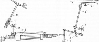
You can control and regulate tire pressure on ZIL 4331 and other modifications using a special device. It is a pressure control valve with a spool-type limiting valve. A head for supplying air to the tires is installed in the wheels. The presence of such a system provides the car with certain advantages in motion:
- By constantly pumping up a broken wheel, you can avoid wasting time replacing it and move on to the repair site.
- You can monitor the pressure constantly and change it if necessary, for example, to improve maneuverability on slippery or loose roads.
- With its help, you can quickly adapt the truck to new operating conditions.
- The faucet has a lever that can be in one of three positions. With its help, you can maintain pressure in the ZIL 130 wheels
, bleed air from the system into the atmosphere and from the brake into the tires to compensate for pressure. To ensure stable operation of the brake system, the valve is equipped with a limiter, which is responsible for preventing air release if the pressure drops to 5.5 kg/cm2.
In addition to the valve and head for air supply, the system also contains a tire valve. It is located in a socket on the axle shafts. With its help, you can forcefully open the air supply channel or completely block it.
What pressure should be in ZIL 130 tires is indicated in the technical documentation for the car, but it is also worth taking into account operating conditions and load. If the road is slippery, then it is better to lower it, thereby making the wheels softer and increasing the contact patch with the surface.
Spare parts for Ural, Kraz, MAZ, Kamaz trucks. Engine parts YaMZ-236, YaMZ-238
__________________________________________________________________________
__________________________________________________________________________
Fuel supply system ZIL-130
___________________________________________________________________________
The fuel system of the ZIL-130 engine (Fig. 17) is forced, with fuel supplied by a diaphragm-type fuel pump. The fuel for the engine is motor gasoline with an octane number of at least 76. The use of lower quality motor gasoline can cause abnormal engine operation (detonation, increased soot formation, increased fuel consumption, burnout of gaskets and cylinder heads, etc.). Rice. 17. Diagram of the ZIL-130 fuel system a - the exhaust valve is open; b - inlet valve is open; 1— fuel pump; 2— fine fuel filter; 3 - carburetor; 4 - settling filter; 5 — fuel level indicator sensor in the tank; 6 — fuel tank; 7 - square; 8 — tank plug; 9 — clip; 10 - rubber gasket; 11 — body; 12 — exhaust valve; 13 — exhaust valve spring; 14 — inlet valve; 15 — intake valve spring; 16 — tank plug lever; 17 — receiving tube; 18 - mesh filter Fuel pump (gasoline pump) ZIL-130 (Fig. 18) - diaphragm, sealed, with a lever for manual pumping of fuel. At ambient temperatures below - 30C, fuel pumping must be done only after the engine has been warmed up by the heater. Do not unnecessarily disassemble the fuel pump to avoid leakage between the connector planes of the cover, head and housing. When disassembling the ZIL-130 gasoline pump, you need to remove the screen and wash it in clean gasoline. The pump must be disassembled and reassembled carefully so as not to damage the diaphragm and gasket. Rice. 18. Fuel pump ZIL-130 1 - exhaust valve; 2 - connecting screw; 3 — pump head; 4 - diaphragm; 5 — rocker arm return spring; 6 — rocker arm; 7 — rocker axis; 8 — lever for manual pumping of fuel; 9 — thrust washer; 10 - pusher; 11 — diaphragm spring; 12 — body; 13 — inlet valve; 14 — rubber gasket; 15 - mesh filter; 16 — fitting for fuel supply; 17 - cover; 18 — outlet fitting When replacing the diaphragm, in order not to damage the sheet of rubberized diaphragm fabric, you must carefully tighten the pusher nut. During assembly of the diaphragm, you should check whether dust particles, sawdust, metal shavings, etc. have gotten between the plates and the diaphragm, as this leads to accelerated wear of the diaphragm. When assembling the fuel pump head with the housing, connecting screws 2 should be tightened when the diaphragm is in the lower position. Checking the installation of valves and diaphragm of the ZIL-130 fuel pump When operating a car, there are often cases when it becomes necessary to disassemble the fuel pump if the filter is dirty, valves, springs, diaphragm are damaged, etc. After eliminating the defects, the ZIL-130 gasoline pump must be assembled in accordance with technical requirements. When completely disassembling and reassembling the fuel pump, it is necessary to install the valves correctly. The valve cage rods must be pressed into their seats so that between the valve and the rod cage there is a distance corresponding to the valve stroke of the following size: for the B9 fuel pump 1.5-1.8 mm for the inlet valve and 2.0-2.3 mm for exhaust valve; for the B10 fuel pump, 0.65–1.45 mm for the inlet valve and 1.15–1.95 mm for the exhaust valve. When replacing the fuel pump diaphragm, the screws securing the head to the pump body must be screwed in with the diaphragm fully retracted to the lowest position. This installation eliminates excess stress in the diaphragm during its operation and thereby increases its service life, and also has a positive effect on pump performance. Rice. 19. Fine fuel filter ZIL-130 1 - inlet; 2 - outlet; 3 — filter housing; 4 — housing gasket; 5 - settling glass; 6 — ceramic filter element; 7 - spring; 8 — bushing; 9 - nut; 10 - clamping screw; 11 — bracket The fine fuel filter ZIL-130 (Fig. 19) with a ceramic filter element and a removable plastic settling cup 5 is installed in front of the carburetor. The filter should be periodically washed with acetone, the filter element should be blown with compressed air, supplying it from inside the element, for which you first need to unscrew the nut and remove the settling cup. When disassembling and washing the filter, you must be especially careful when handling the filter element. It is forbidden to remove the filter element; it should be replaced only after 20-25 thousand kilometers. The ZIL-130 fuel tank is mounted on brackets on the left side member of the frame under the platform. The filler neck of the tank is closed with a hinged sealed cap with two valves (inlet and outlet). This lid arrangement ensures equalization of pressure in the tank and reduces fuel losses from evaporation and splashing. The tank mounting nuts should be checked and tightened periodically. The fuel sediment filter (Fig. 20) is installed on the front bracket of the fuel tank. To wash the element, you need to unscrew bolt 4 of the filter cover and remove housing 1 together with the filter element. When disassembling the settling filter, it is important not to damage gasket 2, which ensures the tightness of the connection between the housing and the lid. Rice. 20. Fuel filter-settler ZIL-130 1 - housing, 2 - gasket; 3 — fuel line to the fuel pump; 4—cover bolt; 5 — fuel line from the fuel tank; 6 — filter element gasket; 7 - filter element; 8 — filter element stand; 9—sump spring; 10 — drain plug; 11 - plug; 12 — filter element plate; 13— holes in the plates for fuel passage; 14 — protrusions on the plates; 15—holes in the plates for the racks When draining dirt from the sump, you must first disconnect the fuel line 5. After unscrewing the plug and emptying the sump, you need to rinse it with clean gasoline; Reinstall fuel line 5 and tighten the plug and gasket. Carburetor ZIL-130 Carburetor ZIL-130 - vertical (Fig. 21), with a falling mixture flow, with a balanced float chamber, two-chamber; each chamber has two diffusers. The required mixture composition is obtained due to pneumatic braking of the fuel and the use of an economizer valve. Rice. 21. Diagram of the K-88 carburetor of the ZIL-130 car 1 - air neck housing; 2 - needle valve; 3 - mesh filter; 4 — filter plug; 5 — channel for balancing the float chamber; 6 — idle jet; 7 - cavity; 8 — full power jet; 9 — air jet; 10 — small diffuser, 11 — annular slot; 12 — nozzle; 13 - air cavity; 14 - hollow screw; 15 — air damper; 16 - automatic valve; 17 — pusher; 18 and 34 — springs; 19 and 21 — rods; 20 — bar; 22— annular groove; 23 — float chamber body; 24 - cuff; 25 — cuff spring; 26 — shock bushing; 27 - hole; 28 — intermediate pusher; 29 and 31 — ball valves; 30 - saddle; 32 — thrust: 33 — economizer channel with mechanical drive, 35 — fuel channel; 36 — plug: 37 — lever; 38 — gasket; 39 and 44 - channels; 40 — discharge needle valve; 41 — idle speed adjustment screws; 42 - rectangular hole; 43 — round hole of the idle system; 45 — throttle valve; 46 — mixing chamber housing; 47 — main jet; 48 — float; 49 - spring The ZIL-130 carburetor has a separate idle system for each chamber, powered from the main fuel channel. To enrich the mixture when the throttle valves are opened sharply, the carburetor has an accelerator pump. To facilitate starting a cold engine, the carburetor has an air damper with an automatic valve and a kinematic connection between the air and throttle valves.
The float chamber, accelerator pump, economizer and air damper are common to both chambers. Below are the main technical data of the carburetor. Characteristics of the K-88 carburetor of the ZIL-130 car Diffuser diameter, mm: - small - 8.5 - large - 29.0 Diameter, mm: - mixing chambers - 36 - air neck - 60 Nozzle capacity when tested with water under pressure of 1000 mm at temperature (20±1)°, cm3/min: - main - 315 - full power - 1150 - economizer valve - 215 - air - 860 Distance from the fuel level in the float chamber to the upper plane of the float chamber housing connector, mm - 18— 19 Float mass, g - 19.7±0.5 Distance between the edge of the throttle valve and the wall of the mixing chamber at the moment of opening the economizer valve with a mechanical drive, mm - 9 The idle system is adjusted with a fully warmed-up ZIL-130 engine and a completely serviceable ignition system a thrust screw 2 (Fig. 22), which limits the closing of the throttle valves, and two screws 1, which change the composition of the mixture. Particular attention should be paid to the serviceability of the spark plugs and the correct gap between their electrodes. It should be taken into account that the carburetor is a two-chamber carburetor, and the composition of the mixture in one chamber is adjusted with the appropriate screw, regardless of the composition of the mixture in the other chamber. When tightening the screws, the mixture becomes leaner, and when unscrewing, it becomes richer.
Rice. 22. Adjusting the idle system of the K-88 carburetor of the ZIL-130 car 1 - adjustment screws; 2 - thrust screw When starting to adjust the idle speed system of the K88 carburetor, you need to tighten the screws all the way, but not too tightly, and then unscrew each three turns. After this, you should start the engine and use the thrust screw to set the throttle opening to the minimum value at which the engine operates quite stably. Then you need to lean the mixture using one of the screws 41 (see Fig. 21), turning this screw 1/4 turn at each test until the engine begins to work with obvious interruptions. Then you should enrich the mixture by unscrewing screw 41 on the ZIL-130 carburetor by 1/2 turn. After completing the adjustment of the mixture composition in one chamber, it is necessary to make adjustments in the second chamber. Having adjusted the composition of the mixture, you should try to reduce the idle speed by gradually unscrewing the throttle valve thrust screw, after which you should again try to lean the mixture using the screws, as indicated above. Usually, after two or three attempts, you can find the correct position for all three adjustment screws. Do not set the engine idle speed to a very low speed. To check the idle speed adjustment, press the throttle pedal and immediately release it sharply. If the engine stops working, the engine idle speed must be increased. After performing operations to adjust the idle system of the K-88 carburetor of the ZIL-130 car, it is necessary to measure the carbon monoxide content in the exhaust gases in the following sequence: - set the gear lever to the neutral position; — connect the tachometer to the engine; — start and warm up the engine to a temperature of 80-90 ° C; — install the gas analyzer sampling device into the muffler pipe to a depth of 300 mm; — set the engine crankshaft speed within 450-500 rpm; — measure the content of carbon monoxide in the exhaust gases. The measurement should be carried out no earlier than 30 s after the required rotation speed has been established. If the carbon monoxide content does not meet the standard, you should adjust the carburetor with screws 1 (see Fig. 22), which change the composition of the fuel mixture of the idle system. The composition of the mixture in each chamber of the ZIL-130 carburetor is controlled by a separate screw. When tightening the screws, the mixture becomes leaner and the carbon monoxide content in the exhaust gases decreases. If the content of carbon monoxide in the exhaust gases is high, screws 1 must be tightened 4 turns and after stabilizing the gas analyzer readings, fix them. If necessary, the operation should be repeated. When adjusting with screws 1, you must constantly monitor the readings of the tachometer and gas analyzer. The crankshaft rotation speed must be constant within specified limits and maintained by regulation using the throttle valve thrust screw. After adjustment at idle speed, it is necessary to measure the carbon monoxide content in the exhaust gases at an engine speed of 1900-1950 rpm. The composition of the mixture in this operating mode is not adjustable. If the carbon monoxide content does not meet the standards, it is necessary to establish the reason for this. An increased content of carbon monoxide in the exhaust gases may indicate the following malfunctions of the power system: excess fuel level in the float chamber; leakage of the seal of the fuel jets of the idle system; dirty air filters. Rice. 23. Diagram of the crankshaft speed limiter for the ZIL-130 engine 1—carburetor throttle valve; 2 and 4 — jets; 3 - lever; 5 — spring of the diaphragm mechanism: 6 — speed limiter; 7 - diaphragm; 8 — rod; 9 and 10 - holes; 11 — throttle valve drive lever; 12 and 13 — tubes; 14 — centrifugal sensor spring; 15 — gasket; 16 — rotor groove for connection with the camshaft; 17 — oil seal; 18 - cover; 19 — screw for adjusting spring tension; 20 - plug; 21 - rotor; 22 — bushing; 23 — sensor housing; 24 - channel; 25 - valve; 26 — valve seat; 27 — centrifugal sensor; 28 — carburetor with speed limiter; A and B - cavities A correctly adjusted K-88 carburetor of a ZIL-130 car should ensure stable operation of a serviceable engine at idle. The maximum engine speed is limited by a pneumatic centrifugal limiter (Fig. 23), consisting of two mechanisms: a centrifugal sensor rotating from the engine camshaft, and a diaphragm actuator that acts on the carburetor throttle valves. The limiter is activated at a crankshaft speed of 3100+200 rpm. The carburetor must be washed with clean gasoline or acetone, followed by blowing with compressed air. The K88 carburetor has rubber and rubberized parts, so washing with acetone or solvents based on it should be carried out only after removing these parts. When disassembling the carburetor, removing the upper housing, it is necessary to unscrew the hollow screw 14 (see Fig. 21). It should be taken into account that the discharge needle valve 40 is not secured and may fall out of the housing. It is strictly forbidden to use wire or other metal objects to clean jets, injectors, channels and holes. It is prohibited to blow compressed air through the assembled carburetor through the fuel supply hole and the balancing tube, as this will damage the float. Air filter ZIL-130 The air filter is oil-inertia, with two-stage air purification and a special air intake pipe for the compressor (Fig. 24). Rice. 24. Air filter ZIL-130 1 and 11 - adapters; 2—oil bath; 3 - reflector; 4, 5 and 10 - sealing gaskets; 6 — filter element; 7 - coupling screw; 8 — wing nut; 9 - screw; 12 — air intake pipe for the compressor; 13 - annular slot; 14 - annular window, 15 - filter housing The ZIL-130 air filter must be periodically cleaned and refilled with oil in accordance with the lubrication chart. To clean, the air filter must be disassembled by first unscrewing screw 9 and then wing nut 8. When cleaning, all filter parts should be thoroughly rinsed in gasoline or kerosene. After washing, the filter element must be soaked in oil; before installing the element in place, excess oil must drain. Oil is poured into the bath up to the horizontal marks - arrows, stamped on the wall of the bath. In addition to marks and arrows, there is an inscription “Oil level” on the wall of the bathtub. If the oil level in the filter bath is higher than the norm, then excess oil will be carried away by the air flow into the engine, which is unacceptable. To lubricate the filter element and fill the filter oil bath, use the same oil as for lubricating the engine. Operating the engine without filters or with a filter without oil is unacceptable. It should be remembered that the service life of the engine largely depends on the correct operation of the air filter, and therefore on its timely cleaning and refilling.
The air supply to the filter is carried out through an air duct in the engine hood, to which the filter is connected by a corrugated pipe.
_________________________________________________________________________
_________________________________________________________________________
_________________________________________________________________________
- Cardan shafts and power take-off Ural-4320
- Transmission gearbox Ural-4320
- Bridges Ural-4320
- Transfer case Ural-4320
- Steering Ural-4320
- Truck cranes and cranes based on trucks
_________________________________________________________________________
_________________________________________________________________________
- Cylinder block and cylinder head YaMZ-236 HE2, YaMZ-236 BE2
- Checking and adjusting YaMZ-236
- Power system and lubrication system YaMZ-236
- Driven and driven clutch discs YaMZ-236, 238
- Cooling and lubrication systems YaMZ-238
- Fuel injection pump YaMZ-238
_________________________________________________________________________
- Kamaz diesel engine
- Repair and adjustment of Kamaz power steering
- Kamaz-152 gearbox with divider
- Gearbox parts for Kamaz-5320 gearbox
- Kamaz transfer case and driveshafts
- Kamaz gearbox repair
- Clutch KamAZ-5320
- Construction of Kamaz-4310 drive axles
- Power steering MAZ-5551, 5549, 5335, 5336, 5337
- Front axle and steering rods MAZ-5551, 5549, 5335, 5336, 5337
- Clutch adjustment MAZ-5551, 5549, 5335, 5336, 5337
- Adjustment and repair of gearboxes MAZ-5551, 5549, 5335, 5336, 5337
- Repair and maintenance of the rear axle MAZ-5551, 5549, 5335, 5336, 5337
- Front axle parts and steering rods MAZ-5516, 5440
- Steering Maz-5516, 5440
- Details of driving axles Maz-5516, 5440
- Clutch device ZIL-130
- Repair of ZIL-130 gearbox
- Repair of rear axle ZIL-130
- Basic parts of the ZIL-130 engine
- Transfer case and power take-off ZIL-131
- Drive axles ZIL-131
- Steering ZIL-131
- Maintenance of ZIL-645 engine parts
Useful tips
For disassembling and assembling wheels, the tool kit supplied with the vehicle includes two mounting blades: one with a flat end and one with a curved grip. The latter simultaneously serves as a jack lever.
According to the operating instructions and repair manual for the 131st car, in order to preserve the tire beads and facilitate all operations, the removal of a tire from a wheel can only be carried out at a specialized stand for tire removal and only in exceptional cases - manually.
Dismantling the wheels, due to the size of the tires for the ZIL 131, is a very labor-intensive task. It will be extremely difficult to cope with this situation alone. In addition, many old wheels sit very tightly on the rim. To disassemble them manually, a sledgehammer and angles are used to help.
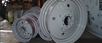
Wheels for ZIL-130
The car wheel of the ZIL-130 car includes the following elements:
- disk with rim;
- tire;
- camera;
- rim tape protecting the camera from mechanical impact from the rim;
- lock ring.
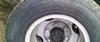
The ZIL-130 is equipped with 260-508 tires, which corresponds to the inch value 9-20, where 9 and 260 are the tire profile width, and 20 and 508 are the nominal rim diameter (in inches and millimeters, respectively). Pneumatic tires.
The permissible air pressure in the tires is 0.53 MPa for the front pairs, 0.6 MPa for the rear and spare pairs, or 5.3 and 6 kgf/cm², respectively.
The rear dual wheels are secured with one nut. All fastening nuts are interchangeable.
Thus, mass-produced ZIL cars are equipped with durable and reliable wheels of different sizes, which are capable of ensuring safe driving in difficult terrain.