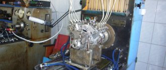
Operating principle of the YaMZ 238 injection pump
The main stages of operation of the fuel pump:
- Fuel is pumped through the fitting. The part is connected to a reduced pressure pipe.
- The small cam shaft as well as the spring begin to move. Therefore the piston moves up and down;
- The cam shaft starts to work.
It is located at the bottom of the YaMZ 238 injection pump. The part rotates in a support and bearings.
A durable regulator responsible for movement is connected to the sections of the unit through a rack, which also rotates in several bushings.
The start is reduced when the corresponding bolt is progressively unscrewed from the rack.
The lubrication and its scheme for the YaMZ 238 injection pump are as follows: central type from the engine oil system. Oil flows only through pressurization to the surface of the corrector.
From this place it moves to the regulator, and then to the cam shaft of the pump.
content .. 1011 12 ..
1.2.
LUBRICATION SYSTEM for YaMZ-238PM and YaMZ-238FM engines
Device
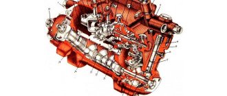
The engine lubrication system (Fig. 14) is mixed - under pressure and splashing. Main and connecting rod bearings, piston pins, bearings are lubricated under pressure
camshaft, rocker arm bushings, pushrod booms, pushrod tips, bearings of the oil pump and its drive; The cylinder liner mirror, camshaft cams, accessory drive gears and rolling bearings are lubricated by splashing.
Rice. 14. Lubrication system diagram
Oil pump of YaMZ-238PM and YaMZ-238FM engines
(Fig. 15). Gear type, mounted on the front main bearing cover and driven by the crankshaft gear through the intermediate gear; consists of two sections - main and radiator.
The main (discharge) section of the pump supplies oil to the main oil line through a coarse filter 14 connected in series (see Fig. 14). A bypass valve 12 is installed in the coarse filter housing (Fig. 16), which, when the pressure difference before and after the filter is equal to 1.8-2.3 kgf/cm2 (if the filter element is dirty), part of the crude oil opens, bypassing the filter , enters the oil line. By the time the bypass valve 12 begins to open, the contacts of the alarm will close; at this moment the signal light in the office lights up. After the filter, the oil enters the central oil channel, and from there through the channels in the cylinder block to the bearings of the crankshaft and camshaft. From the crankshaft bearings, through a system of channels in the crankshaft and connecting rods, oil is supplied to the bearings of the upper heads of the connecting rods. From the camshaft, oil is directed in a pulsating flow into the channel of the pusher axis and from there through the channels in the pushers, through hollow rods and rocker arm drillings - to all rubbing pairs of the valve drive. From the central oil channel through the outer tube, oil flows to the turbocharger bearings through an additional fine filter (Fig. 17).
After the coarse filter, a centrifugal fine oil filter 1 is connected parallel to the main oil line (see Fig. 14), which passes up to 10% of the oil passing through the lubrication system. The purified oil is drained into the pan.
The pressure section of the oil pump is equipped with a pressure reducing valve 10 (see Fig. 14), which transfers oil into the sump at pressure
at the pump outlet more than 7-8 kgf/cm2.
A safety valve 5 is installed in the body of the radiator section of the pump, adjusted to a pressure of 0.8-1.2 kgf/cm°. To stabilize the pressure, a differential valve 6 is included in the lubrication system, adjusted to start opening at 5.2-5.4 kgf/cm2.
Rice. 15. Oil pump
content .. 10
11 12 ..
Injection pump device YaMZ 238
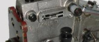
In this figure you can carefully examine the diagram of the YaMZ 238 fuel injection pump.
Main elements of the system:
- TN housing;
- Valve;
- Bolt (used to limit maximum rotation);
- Regulator and coupling;
- Bolt (used to limit minimum rotation);
- Bracket as well as lever;
- Fuel pump;
- Bolt (used to regulate starting feed);
- Boost fuel supply corrector.
The YaMZ 238 injection pump device includes special sections (their number is equal to the number of cylinders).
The design of the plunger pair is modeled in such a way that the dosage of fuel is carried out by adjusting the delivery moments.
Therefore, the main design of the YaMZ injection pump includes:
- Plunger and bushing. It is these elements that are connected to form a plunger pair. Do not forget that the gap between the parts should be minimal.
- As soon as the piston moves inside the cylinder, a rapid injection of fuel occurs.
The YaMZ 238 injection pump circuit cannot function without a bushing and, of course, a plunger.
If the parts fail, the engine's high-pressure fuel pump will break.
Therefore, for effective operation, it is necessary to monitor the minimum distance between the elements and adjust the YaMZ 238 injection pump.
Malfunctions of the fuel pump can also be associated with the accumulation of contaminants and jamming of the part.
In this case, we advise you to inspect the YaMZ injection pump device and, if necessary, clean it.
If necessary, adjust the bushing and plunger.
Read more about how to repair YaMZ fuel injection pumps and adjust the unit in the following articles on our blog.
Don’t forget that you can always buy YaMZ fuel injection pumps in our catalog.
Fuel injection pump of the YaMZ-238 diesel engine
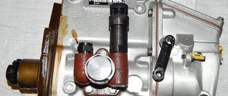
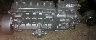
The fuel injection pump of the YaMZ-238 diesel engine of Maz, Kraz, Ural cars, and the K-700 tractor assembly is shown in Fig. 1.
Rice. 1 — injection pump YaMZ-238
1 – high pressure fuel pump; 2 – bypass valve; 3 – damper coupling; 4 – bolt for limiting the maximum rotation speed; 5 – speed regulator; 6 – regulator control lever; 7 – bolt for limiting the minimum rotation speed; 8 – stop bracket; 9 – fuel priming pump; 10 – starting feed adjustment bolt; 11 – boost fuel supply corrector.
A – lever position at minimum idle speed; B – lever position at maximum idle speed; B – position of the bracket during operation; G – position of the bracket when the feed is turned off
The YaMZ-238 fuel injection pump combines a speed regulator 5, a fuel priming pump 9 and a damper clutch 3 into one unit.
Design of the YaMZ-238 diesel fuel injection pump
The high-pressure fuel pump TNVD YaMZ-238 for Maz, Kraz, Ural cars, and the K-700 tractor consists of sections, separate pumping elements located in a common housing.
The number of sections is equal to the number of engine cylinders.
The structure of the YaMZ-238 injection pump section is shown in Fig. 2.
Rice. 2 — Section of the high pressure fuel pump YaMZ-238
1 – pump housing; 2 – lower plate of the pusher; 3 – pusher spring; 4 – upper plate of the pusher; 5 – rotary bushing; 6 – plunger; 7 – plunger bushing; 8 – discharge valve seat; 9 – discharge valve; 10 – valve stop; 11 – fitting; 12 – pressure flange; 13,14 – gaskets; 15 – section body; 16 – rack; 17 – pusher; 18 – pusher roller; 19 – cam shaft
In the pump housing 1 there are housings of sections 15 with plunger pairs, discharge valves and fittings 11, to which high-pressure fuel lines are connected.
Discharge valve 9 and valve seat 8, as well as plunger 6 with sleeve 7 are precision pairs that can only be replaced as a set.
The plunger sleeve is locked in a certain position by a pin pressed into the section body.
The plunger 6 is driven from the cam shaft 19 through the roller tappet 17.
Spring 3, through the lower plate 2, constantly presses the pusher roller to the cam
From turning, the pushers, which have flats on the side surfaces, are held by clamps pressed into the body of the YaMZ-238 injection pump pump.
The design of the plunger pair allows fuel dosing by changing the start and end times of the supply.
To change the amount and moment of the start of fuel supply, the plunger in the sleeve is turned by a rotary sleeve 5 (Fig. 2), which engages with rack 16.
Adjusting the uniformity of fuel supply at maximum mode by each section of the fuel injection pump of the YaMZ-238 diesel engine of Maz, Kraz, Ural cars, and the K-700 tractor is carried out by turning the section body with the section fastening nuts loosened.
Changing the geometric start of injection depending on the amount of feed (engine load) is ensured by control edges made at the end of the plunger.
Operating principle of the fuel injection pump section of the YaMZ-238 diesel engine
When plunger 6 moves downward under the action of spring 3, fuel under low pressure created by the fuel priming pump enters through a longitudinal channel in the housing into the space above the plunger.
When the plunger moves upward, fuel enters the high-pressure fuel line of the YaMZ-238 diesel engine through the injection valve and is transferred into the fuel supply channel until the end edge of the plunger blocks the inlet hole of the bushing.
With further upward movement of the plunger, the pressure in the space above the plunger increases sharply.
When the pressure reaches such a value that it exceeds the force created by the injector spring, the injector needle will rise and the process of injecting fuel into the engine cylinder will begin.
With further upward movement of the plunger of the YaMZ-238 injection pump, the cut-off edges of the plunger open cut-off holes in the sleeve, which causes a sharp drop in fuel pressure in the discharge line, the nozzle needle landing on the locking cone of the nozzle and stopping the supply of fuel to the combustion chamber.
On the inner surface of the plunger sleeve 7 there is an annular groove, and in the wall there is a hole for draining fuel that has leaked through the gap in the plunger pair.
The seal between the plunger bushing and the section body, the section body and the pump body is carried out with rubber rings.
From the cavity around the plunger bushing, the leaked fuel flows through the groove on the plunger bushing into the low pressure cavity of the pump housing and then through the bypass valve and pipeline into the fuel tank.
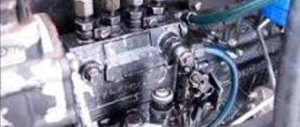
In the lower part of the housing of the fuel pump TNVD YaMZ-238
Maz, Kraz, Ural cars, K-700 tractors have a cam shaft.
The cam shaft rotates in tapered roller bearings and an intermediate support.
The cam shaft is installed with an interference of 0.01 - 0.07 mm, which is provided by the adjuster and gaskets installed between the bearing cover and the pump housing.
The sections are connected to the YaMZ-238 high-pressure fuel injection pump speed controller via a rail.
The YaMZ-238 injection pump rack moves in guide bushings pressed into the pump housing.
At the end of the rack protruding from the pump there is a bolt 10 (Fig. 1), with which it rests against the protective cap when the rack is in position before starting the engine.
When the bolt is removed from the rack, the starting feed decreases.
Lubrication of the YaMZ-238 injection pump is centralized, from the engine oil system.
The oil is supplied to the boost corrector, from where, merging into the cavity of the regulator, it enters the cavity of the pump cam shaft.
Injection pump pump speed regulator YaMZ-238
The rotation speed regulator of the fuel injection pump YaMZ-238 for Maz, Kraz, Ural cars, and the K-700 tractor (Fig. 16) is a mechanical all-mode direct action with overdrive transmission to the load drive, designed to maintain the speed mode of engine operation set by the driver by automatically changing the amount of fuel supplied to depending on changes in engine load.
Rice. 3 — Speed regulator of the fuel injection pump of the YaMZ-238 engine
1 – boost fuel supply corrector; 2 – axis of the double-arm lever; 3 – inspection hatch cover; 4 – regulator spring; 5 – double-arm lever; 6 – rack lever spring; 7 – double-arm lever screw; 8 – buffer spring; 9 – buffer spring housing; 10 – adjusting bolt; 11 – spring lever shaft; 12 – negative corrector; 13 – corrector spring housing; 14 – negative corrector spring; 15 – backstage bracket; 16 – negative corrector bushing; 17 – regulator lever; 18 – negative corrector lever; 19 – power adjustment screw; 20 – rack lever; 21 – backstage; 22 – heel; 23 – cargo coupling; 24 – regulator weights; 25 – load holder; 26 – load axis; 27 – drive gear; 28 – crackers; 29 – load holder roller; 30 – glass; 31 – spring lever 32 – rack rod; 33 – rack; 34 – stop
In addition, the YaMZ-238 injection pump regulator limits the maximum engine speed and ensures engine operation in idle mode.
The YaMZ-238 injection pump regulator has a device for turning off the fuel supply at any time, regardless of the engine operating mode.
By automatically maintaining the speed mode under changing loads, the regulator ensures economical engine operation.
Operating settings and adjustments of the YaMZ-238 injection pump
The minimum idle speed is regulated by bolt 7 (Fig. 1) and buffer spring housing 9 (Fig. 16);
The maximum idle speed (beginning of rack ejection) is regulated by bolt 4 (Fig. 14).
The rated power (feed) is adjusted by bolt 10 and adjusted by screw 19 (Fig. 16).
The pre-tension of the spring (the difference in revolutions between the end and the beginning of the ejection of the rack) is adjusted by screw 7.
The fuel supply at 500 min-1 is regulated by the reverse corrector nut 12.
The pre-tension of the reverse corrector spring (the speed at which the corrector begins to operate) is regulated by the corrector body 13 (Fig. 16).
To the features of adjusting the YaMZ-238 injection pump
Maz, Kraz, Ural cars, K-700 tractor, it should be noted that in order to ensure reduced force on the control lever, the spring lever when adjusting the speed of rotation of the start of the governor action must be as close as possible to the stop in the governor body that limits its rotation.
The start of action of the regulator can be adjusted using the screw of the double-arm lever.
Damper coupling of the injection pump pump of the YaMZ-238 engine
The high-pressure fuel pump TNVD YaMZ-238 is equipped with a damper coupling, which is installed on the conical surface of the front end of the cam shaft with tension created by a ring nut and secured against rotation by a key.
The YaMZ-238 injection pump damper coupling is designed to protect mechanisms from destruction.
The YaMZ-238 injection pump damper coupling is a non-separable structure with a freely rotating flywheel in a special high-viscosity fluid.
Dents on the coupling body render it inoperable.
All necessary parts can be purchased in our catalog