Permissible clearance dimensions of the piston assembly
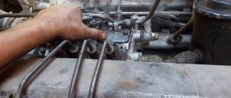
When you are going to adjust the piston clearances of the YaMZ power unit, as well as during their next analysis, the rocker arms are pressed according to the location of the cylinder heads.
- Right side row. Press the exhaust pistons against the front part of the axle, and the intake pistons against the locking rim.
- Row on the left side. The outlets are to the locking rim, and the inlets are to the frontal part of the axle.
Reference! The exhaust pistons on the right are installed closer to the cooler, and those on the left are the opposite.
To adjust the slots, you need to slightly unscrew the calibration bolt washer. Next, place the probe in the slot and set the free space within 0.25 - 0.30 mm; to do this, you need to twist the bolt using a screwdriver. After installation, you need to tighten the washer; to do this, you also need to support the bolt with a screwdriver. After tightening, a probe with a size of 0.25 should easily pass into the gap, and a 0.3 mm probe with force.
It is worth noting that due to the possible runout of the contacting elements of the gas distribution mechanism (GRM) when the crankshaft rotates, after calibrating the pistons, an opening within 0.2 - 0.4 mm is allowed.
How to correctly set the ignition on a YaMZ 7511 engine
For owners of trucks with a YaMZ 7511 power unit, it is necessary to correctly set the fuel injection advance angle (FIA). This is required for the normal and high-quality operation of all transport. How to correctly set the ignition on the YaMZ 7511 will be discussed further.
It is necessary to assess the condition and calibrate the thermal slots of the piston assembly before starting it, as well as after running it in, but not earlier than 15 minutes after the internal combustion engine (ICE) has stopped.
Before you begin calibrating the slots, you need to activate the fuel supply with the regulator bracket, and you also need to remove the valve covers of the YaMZ 7511 cylinder heads. Using a torque wrench, evaluate the degree of tightening of the washers securing the rocker arm axles.
MOTORISTS FORUM
A forum for communication between mechanics, drivers and the curious
- Unanswered topics
- Active topics
- Search
- List of forumsPublic forumsDiesels and repair of diesel equipment
- Search
Checking the operation of the turbocharger on the YaMZ-7511.
Checking the operation of the turbocharger on the YaMZ-7511.
Post by Grog1570 » Jun 09, 2012, 11:14 pm
Re: Checking the operation of the turbocharger on the YaMZ-7511.
Post by Name1esS » June 10, 2012, 11:40 am
Re: Checking the operation of the turbocharger on the YaMZ-7511.
Post by Grog1570 » Jun 10, 2012 11:52 am
Re: Checking the operation of the turbocharger on the YaMZ-7511.
Post by Name1esS » June 10, 2012, 12:29 pm
Re: Checking the operation of the turbocharger on the YaMZ-7511.
Post by Name1esS » June 10, 2012, 12:32 pm
Re: Checking the operation of the turbocharger on the YaMZ-7511.
Post by Name1esS » June 10, 2012, 12:43 pm
Re: Checking the operation of the turbocharger on the YaMZ-7511.
Post by propellerOK » Jun 10, 2012, 9:01 pm
Re: Checking the operation of the turbocharger on the YaMZ-7511.
Post by Name1esS » June 10, 2012, 9:37 pm
Re: Checking the operation of the turbocharger on the YaMZ-7511.
Post by Name1esS » June 10, 2012, 9:41 pm
Re: Checking the operation of the turbocharger on the YaMZ-7511.
Post by propellerOK » Jun 11, 2012, 07:18
Re: Checking the operation of the turbocharger on the YaMZ-7511.
Post by Name1esS » June 11, 2012, 9:25 pm
Re: Checking the operation of the turbocharger on the YaMZ-7511.
Post by AB-Engine » June 11, 2012, 21:29
Re: Checking the operation of the turbocharger on the YaMZ-7511.
Post by Grog1570 » June 12, 2012, 00:43
Re: Checking the operation of the turbocharger on the YaMZ-7511.
Post by Name1esS » June 12, 2012, 01:23
Re: Checking the operation of the turbocharger on the YaMZ-7511.
Post by Name1esS » June 12, 2012, 01:25
- Public forums
- ↳ Gasoline engines and their repair
- ↳ Diesels and repair of diesel equipment
- ↳ Repair and restoration of motor parts
- ↳ Motor diagnostics
- ↳ Motor electrics and electronics
- ↳ Motor spare parts, oils and other materials
- ↳ Tools, equipment and information for motor repairs
- ↳ Organization of motor repairs
- ↳ Motor examination
- ↳ Theory, workflow, design and production of motors
- ↳ Tuning and boosting
- ↳ History of engine building and technical achievements
- ↳ Smoking room for mechanics
- ↳ Notice board
- Closed forums
- ↳ Archive
- List of forums
- Delete cookies
- Contact the administration
Photo report: Engine disassembly
Almost just before leaving for permanent residence on another collective farm, an old acquaintance, whom I had not seen for 15 years, turned to me and asked me to overhaul the engine of his Ant. To be honest, I didn’t have much of a desire to get involved with this Soviet chatterbox, to say the least... But after thinking about it and playing out the situation in my head that I would have to sit in a new place for some time without my favorite job, I agreed and immediately began the repairs. I will not go into the essence of the disassembly in particular within the framework of this article - I will only outline the main points and, based on my experience, I will try to describe the most common malfunctions and errors during repairs.
The engine had the following symptoms before being repaired:
- Bad start
- Oil leak
- Weak traction
- Increased noise during operation
- The winding lever did not return to its place
- Depressurization of the crank chamber, as well as wear of the seals
- Poor quality assembly
- The piston died
- Bearing wear
- Kickstarter return spring broke
Everything else, including the gearbox and clutch, did not cause any complaints during operation. However, first things first.
Before a major overhaul, I don’t wash the engines - I just drain the oil, pull it off the frame and get to work.
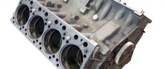
Removing and checking the piston (CPG)
Remove the cylinder head (cylinder head).
The cylinder head gasket held up well, as evidenced by the absence of oil leaks.
In the upper part of the cylinder opposite the exhaust window, we feel the groove with our finger. If it feels a clearly perceptible so-called “wave”, “step”, that is, a drop, then such a cylinder is no longer subject to further use. It needs to be either bored to repair size or bought a new one.
The wear can be easily felt in the place where the piston rings do not reach the end of the cylinder. In the place where the piston rings do not work, the nominal factory size is maintained, but in the place where they work, the metal wears out. That is why a transition is formed at the boundary of these two sections, which is larger the greater the wear of the cylinder.
In my case, as expected, the wear was clearly palpable and the cylinder mirror was covered in nicks and scratches.
A bunch of hay that blocked the flow of cooling air, in my opinion, did not add efficiency to the cooling system... How can you even drive like that?
The piston turned out to be burst and, moreover, according to the good old collective farm tradition, it was treated with sandpaper. As indicated by numerous risks on its surface.
After removing the clutch cover and removing the kickstarter shaft, the reason for the freezing of the winding lever was found - the return spring had burst in half.
The motor chain turned out to be stretched, but not critically.
Removing the clutch
Unscrew the nuts and remove the pressure plate from the basket.
Unbend the lock washer, insert a tin rod or stick under the tooth of the motor transmission sprocket and unscrew the nut on the crankshaft journal (right-hand thread).
Unbend the lock washer, fix the inner clutch drum with a puller, which is a clutch disc with a welded piece of tire, and unscrew the nut (left-hand thread).
We take out the discs and drum.
Remove the basket from the shaft along with the chain and sprocket.
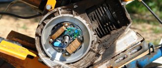
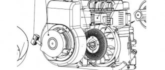
Removing the dyno starter
We remove the cooling casing and then, if the engine is not converted to a magneto, remove the ignition breaker cam. Hold the dyno starter rotor by the fan and unscrew the nut. If you cannot hold the rotor in this way, fix the crankshaft with something and unscrew the nut.
We pull off the rotor with a puller. The rotor can be pulled off either with a standard puller or with a homemade one. Depending on the situation, I use both standard and homemade ones.
Analysis of previous repair errors
We remove the flange on which the stator is mounted and carefully inspect the connector plane for interference by “drop-dead handles”.
No matter how many times I repair Ants, I come across the fact that all sorts of “drop-dead little hands” seal the oil channel through which oil flows to the crankshaft main bearing and oil seal. I'm already tired, honestly - how much can you? Why cover it up?
It doesn’t matter to me, but how do you think the bearing and oil seal should work without lubrication? Admire what happens to the main bearing when it runs dry.
We unscrew the bolts and half the crankcase.
What's the result?
The crankshaft has been taken away - to say that it is worn out is to say nothing... The gearbox bearings, like the main bearings, have gone to the same place - to the crankshaft: in the trash. The gearbox, with the exception of one fork, did not cause any complaints. By the way, the clutch too.
Now the question is: what to do with all this junk? Buy a “plasticine” crankshaft from no one’s making and mold it into the engine. I was initially against this idea. In general, we found a used engine for a ruble and removed the crankshaft from it. Of course I had to tinker with him. Since the thread was clogged, I sharpened it and straightened it with a sharpening tool.
After correcting the threads, I checked the crankshaft for runout. There was no need to worry - the beating of the trunnions did not exceed one hundredth of a millimeter with a tolerance of three hundredths. By and large, it would have been necessary to replace the bushing of the upper head of the connecting rod, but time was running out and the bushing was not very worn. In all other respects, the crankshaft did not disappoint and this purchase can safely be called a success.
How to set the ignition on an Ant scooter in 5 simple steps?
The electrical circuit of the Ant scooter is quite simple and does not contain heavy components. It is used for three main tasks:
- Ignition of the air-fuel mixture in the cylinder. Due to this action, the piston moves, transmitting torque to the flywheel.
- Starting a cold and warm engine.
- Supplying current to lighting fixtures and signal signs (turn signals, parking lights, brake lights).
Ant's electrical equipment is a system with one wire, and the second is the body of the moped itself. All equipment has excellent insulation, eliminating the possibility of short circuits and harm to the driver. Maintenance of electronics on a motorcycle consists only of regular cleaning of the terminals. However, to find the problem, you need to keep a tester at hand. He will accurately determine the problem that is preventing the operation of electrical equipment.
Ignition installation
Installing the ignition on an Ant scooter, as on any motorcycle with a single-cylinder engine and a battery ignition system, does not require special knowledge or effort. All you need is very thin paper, a narrow rod and a set of keys. So, how to set the ignition on an Ant scooter:
- Remove the spark plug and set the piston to top dead center (hereinafter referred to as TDC).
- Insert a rod through the hole from which the spark plug was removed and press it against the piston head. Make a notch at a length of 4.5-5 mm
- Close the breaker contacts when the piston is at TDC. Place paper between them and pinch.
- Turn the crankshaft counterclockwise as slowly as possible and pull the piece of paper at the same time.
- When the paper is released when the piston is lowered to the depth of the mark made, the ignition will be set correctly.
We recommend reading:
The process of calibrating the slots of the piston assembly of the YaMZ 7511 engine
The adjustment of the slots is determined by the operating sequence of the cylinders. For the YaMZ 7511 272 engine – 1-5-4-2-6-3-7-8. The setup procedure is as follows.
Cylinder torque problem #1:
- using a special key, turn the crankshaft from left to right (relative to the fan);
- At the same time, you need to monitor the activity of the intake piston of cylinder No. 1;
- the moment is established when the valve completely rises, in other words, closes;
- then the shaft must be turned another third of a turn.
Cylinder No. 1 now undergoes a compression process with both pistons closed.
To calibrate the slots of the next cylinder you need:
- rotate the crankshaft in the direction of torsion until the pistons of the adjusted cylinder are completely closed;
- then perform another third of a turn.
Further calibration of the pistons of the YaMZ power unit must be carried out similarly to the indicated points.
Specifications
The design of the YaMZ 7511 motor is somewhat different from its predecessors. The designers have improved a number of components and assemblies, which made it possible not only to increase the power of the internal combustion engine, but also its service life. Thus, the following constructive changes were made:
- A liquid-oil heat exchanger is installed.
- A high-performance water pump has been installed.
- Improved liner-piston group with oil cooling system.
- Upgrading high pressure fuel pumps.
Now let's look at the main technical characteristics of the YaMZ 7511 engine:
| Name | Characteristic |
| Type | Diesel, turbocharged diesel |
| Volume | 14.86 liters (14,860 cc) |
| Configuration, parameter | V-shaped |
| Number of cylinders | 8 |
| Number of valves | 16 |
| Econorm | Euro 2 |
| Cylinder diameter | 130 mm |
| Compression ratio | 16,5 |
| Cooling | Liquid |
| Valve mechanism | OHV |
| Material of block and head | Cast iron |
| Resource | 800,000 - 1,000,000 km |
| Fuel | Diesel fuel |
| Cylinder operating order | 1-5-4-2-6-3-7-8 |
| Applicability | Onboard vehicles, chassis MAZ-533608-020, MAZ-533608-021, MAZ-533608-043, MAZ-630308-020, MAZ-630308-021, MAZ-630308-040, MAZ-631708-010, MAZ-631708- 020, MAZ-631708-030, MAZ-631708-041, MAZ-631708-061; truck tractors MAZ-543208-0204, MAZ-544008-030-020, MAZ-544008-030-021, MAZ-642208-020, MAZ-642208-022, MAZ-640308-020-010, MAZ-640308-020 - 020; timber trucks, log trucks MAZ-641708-220, MAZ-630308-226 |
Differences between YaMZ turbocharged diesel engines
The need to increase the power of the diesel engine led to significant modifications to key components. The characteristics of the crankshaft were changed, the structure of the cylinder block and CPG was modified. The power units of the YaMZ-238 family have acquired a system with pressurized air through a turbine. The main element of the system is a turbine installed in addition to the engine. To confidently comply with Euro-1 standards, turbocharged diesel engines of the 238 series received a liquid-oil heat exchanger, a high-performance water pump, and the CPG was supplemented with an effective cooling system. Plus, the diesel engine was equipped with a charge air cooling system and an improved fuel system.
Diesel units YaMZ-238 Turbo, corresponding to the Euro-0 standard, are essentially the same forced engines YaMZ 238 M2. One of the main design features compared to atmospheric modifications is the YaMZ 238 turbine in an improved version.
Auto catalog
- Cars
- VAZ
- UAZ
- GAS
- AZLK
- IZH
- ZAZ
- ZIL
- LuAZ
- RAF
- BYD
- Chevrolet
- Daewoo
- Geely
- Great Wall
- Hyundai
- Lifan
- Tata
- Trucks and trailers
- Autocomponent Plus
- BelAZ
- Bryansk Arsenal
- GAS
- ElAZ
- ZIL
- KAZ
- KamAZ
- KrAZ
- Madara
- MAZ
- MZKT
- MoAZ
- NefAZ
- SZAP
- Tonar
- UralAZ
- CHMZAP
- BAW
- DAF
- DongFeng
- FAW
- Foton
- HOWO
- Hyundai
- IVECO
- JAC Motors
- MAN
- Shaanxi
- Studebaker
- Tata
- TATRA
- Volvo
- Buses
- AMAZ
- Bogdan
- ZIL
- KAVZ
- KamAZ
- LAZ
- LZGMP
- LiAZ
- NefAZ
- GROOVE
- Hyundai
- Ikarus
- Karosa
- Neoplan
- Tractors and combines
- Bobruiskagromash
- BEMZ
- VgTZ
- Voronezhselmash
- VTZ
- Gomselmash
- DKZ
- KZK
- Kirovets-Landtechnik
- Clover
- A red star
- Lidselmash
- LTZ
- Mozyr MZ
- MTZ
- NefAZ
- PTZ
- Sibselmash
- TeKZ
- Equipment-service
- TKZ
- HZTSSH
- KhTZ
- YuMZ
- Amity
- CASE IH
- Fortschritt
- Foton
- Lemken
- MacDon
- TIGARBO
- Special equipment
Evaluation and calibration of the YaMZ-7511 fuel injection advance angle
To adjust the UOVT, there are a pair of hatches on the flywheel housing of the YaMZ 7511. On the disk itself there are corner markers at two points: for the bottom pointer this information is indicated in numerical format, for the side pointer - in alphabetic format.
Certain letters correspond to certain parameters:
- “A” – 20th;
- “B” – 15s;
- "Ei" – 10D;
- “G” – 5s.
Advice! The fuel injection advance angle should be 6J*1.
It is necessary to turn the crankshaft from left to right (from the cooler side) until the line on the disk that corresponds to the UOVT is aligned. It is worth noting that the pistons of the first cylinder must be closed.
As mentioned earlier, you need to turn the crankshaft using a special wrench using the pulley fixation screw. The flywheel mark must align with the pointer mark. If the combination does not occur, then you should do the following:
- loosen the screw of the terminal connection;
- by twisting the damper, align the strokes;
- carefully fix the bolt.
In this case, the deviation of the plate package from the position in one plane is permissible by 1 mm in both directions. The deviation must be measured at the places where the plates are fixed.
Adjusting the fuel injection advance angle of a MAZ with a YaMZ engine
Checking and adjusting the MAZ fuel injection advance angle
To adjust the fuel injection advance angle, two hatches are provided on the flywheel housing (see Fig. 1), and the angle values are marked in 2 places on the flywheel.
For the lower indicator 3, these values are made on the flywheel in digital expression, and for the side indicator 4 - in alphabetic expression, while the letter “A” corresponds to the value. in numerical terms 20°; letter “B” - 15°; letter “B” -10°; letter "G" - 5°.
Rotate the engine crankshaft clockwise (from the impeller side) until the marks on the crankshaft pulley and the front gear cover or on the flywheel align with the mark corresponding to the installation advance angle of diesel fuel injection:
In this case, the valves in the first cylinder must be closed.
Rotate the crankshaft in two ways: either with a wrench using the crankshaft pulley mounting bolt or with a crowbar using the holes in the flywheel (Fig. 2) with the flywheel housing hatch cover removed.
At the moment of aligning the marks, mark “A” on the end of the coupling (Fig. 3, 4) should align with mark “B” on the indicator. If the marks do not align, you need to adjust.
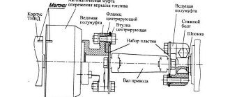
The procedure for adjusting the injection advance angle of YaMZ-236NE2, BE2 engines (Fig. 3):
— loosen the tightening of bolt 2 of the terminal connection: flange 3 — drive coupling half 1;
— by turning the damper coupling, align the indicated marks;
— without disturbing the aligned position of the marks, tighten the terminal connection bolt with a torque of 16.18 kgcm. In this case, the deviation of the plate package from its position in one plane should be within ±1 mm. Take measurements near the places where the plates are attached. If corrugations appear on the plates 4, they are eliminated by alternately loosening and then tightening with a torque of 11. 12.5 kgcm of the four bolts 5 securing the plates to the flange of the coupling half and to the damper coupling;
— check the correct setting of the injection advance angle.
The procedure for adjusting the injection advance angle of YaMZ-236N, B, NE, BE engines (Fig. 4):
— check the tightness of the coupling half 3 on the drive shaft 1 and the tightening of the terminal bolt 5 (tightening torque 43.2...58.9 Nm (4.4...6 kgcm));
— unscrew (loosen) two bolts 4 and by turning the advance clutch, use the oval holes on the flange of the coupling half to align the marks “A” and “B”;
on engines equipped with a U-shaped fuel injection pump, the setting angle of fuel injection advance is 6˚… 7˚
on engines equipped with a V-type fuel injection pump, the setting angle of fuel injection advance is 10˚…11˚
— without disrupting the aligned position of the marks, tighten the bolts 4 of the drive with a tightening torque of 43.2...58.9 Nm (4.4...6 kgcm). In this case, the deviation of the plate package from its position in one plane should be within ±1 mm. Take measurements near the places where the plates are attached;
- Rotate the crankshaft and check that the injection timing is set correctly. The discrepancy between the marks should be no more than one division or 1° of rotation of the crankshaft.
Check the presence of oil in the fuel injection advance clutch (YMZ-236N, B, NE, BE engines), and, if necessary, add oil; to check, set the clutch with its holes in the upper position and unscrew the plugs. When the clutch is slowly turned 70°, oil should begin to flow out of one hole. After adding oil, tighten the plugs.
The fuel injection advance angle must be set using a momentoscope installed on the fitting of the 1st section of the fuel injection pump.
The injection advance angle should be:
— for the YaMZ-238FM engine — 23 ˚;
— for the 51M3-238PM engine — 22 °.
The fuel injection advance angle must be set in the following order:
— make sure that the marks on the injection advance clutch and the drive half of the fuel pump drive are in the correct relative position. The marks should be on one side;
— remove the high pressure pipe of the first section of the injection pump;
— install a momentoscope on the fitting of the first section of the pump (see Fig. 5);
— turn on the fuel supply with the regulator bracket;
- pump fuel into the engine power supply system by unscrewing the handle of the manual booster pump and, moving it up and down, pump the system for 2 - 3 minutes. After pumping, screw the pump handle all the way;
— rotate the engine crankshaft clockwise (as viewed from the fan side) using a wrench by the pulley mounting bolt or a crowbar by the holes in the flywheel until fuel appears in glass tube 1 (see Fig. 5). Pour excess fuel out of the glass tube by shaking it with your finger;
— turn the crankshaft counterclockwise approximately ⅛ turn. Then, slowly turning it clockwise, carefully monitor the fuel level in the glass tube. The moment the fuel begins to move in the tube corresponds to the start of fuel supply by the 1st section of the pump.
With proper adjustment, at the moment the fuel begins to move, the mark on the crankshaft pulley 2 should be opposite the corresponding mark on the timing gear cover (Fig. 6) or a similar mark on the flywheel 2 should coincide with the pointer on the flywheel housing (Fig. 7).
If at the moment the fuel begins to move in the pipe, the marks have not yet aligned, it is necessary to unscrew the bolts and turn the fuel pump drive shaft coupling on the flange against the direction of its operating rotation, then tighten the fastening bolts and check the injection timing again. The discrepancy between the marks should be no more than one division or 1 crankshaft rotation.
If, at the moment the fuel begins to move, the risk tube has already passed the combined position, the drive roller coupling must be turned in the direction of its operating rotation. The displacement of the drive shaft coupling relative to its flange by one division corresponds to four divisions on the flywheel or timing gear cover.
After adjusting the advance angle, the coupling mounting bolts must be tightened.
If the engine is equipped with a high-pressure fuel pump drive of a new design with indicator 13 (Fig. 8), then the fuel injection advance angle is adjusted without a torqueoscope as follows. Align the marks shown in Fig. 30 and 31; on the end of the coupling 12) must align
- If the marks “a” and “b” are not aligned, you need to unscrew the two nuts 7 and by turning the injection advance coupling, use the oval holes on the flange b of the coupling half to align the indicated marks. Without disrupting the combined position of marks “a” and “b”, tighten the nuts of the 7 bolts and the flange of the coupling half and, by turning the crankshaft, check that the injection advance angle is set correctly.
Source
Price list
- Spare parts for Volzhanki cars
- Spare parts for Gazelists
- Spare parts for trucks Lawns
- Spare parts for GAZ-71 caterpillar
Calibration of fuel equipment on the YaMZ 7511 engine
After setting the ignition on the YaMZ 7511 and warming up the engine to normal operating temperature, calibration is required. First you need to set the power at a crankshaft torque intensity of 1900 50 min-1. Its indicator for the YaMZ 7511 power unit is 290+4 kW, while the hourly fuel consumption is no more than 66 kg/h. When finished, push the cap washer onto the power calibration bolt until it stops.
Reference! To maintain the required temperature of the fuel when measuring flow, it is necessary to prevent the volume of liquid from decreasing to less than 2/3 of the height of the container.
In addition, timely and thorough lubrication is responsible for the condition of the motor. Special attention must be paid to the YaMZ 7511 oil pump. If necessary, it is worth repairing or replacing.
Now there should be no questions about how to correctly set the ignition on the YaMZ 7511. You can carry out the procedure yourself. If you are not confident in your abilities, be sure to contact the service center. Qualified technicians will help resolve your problem for a fee. When setting up on your own, there is a high chance of making a lot of mistakes.
Date of publication: 04/18/2019
Service
Servicing the YaMZ 7511 engine is quite simple, since there are no special differences from servicing its older brother 238. Each scheduled service must be carried out at intervals of 20,000-25,000 km. If you follow the maintenance and repair instructions, you must perform the following series of operations:
- Change of oil.
- Adjusting the valve mechanism.
- Replacing filters. So, depending on the engine modification, the following filter elements may or may not be present: a fine and coarse oil filter, a filter element for coarse and fine fuel purification, an air filter, an eco-filter for exhaust.
- Cleaning the injectors.
- Adjustments related to the high pressure fuel pump.
- Other operations aimed at maintaining the power unit.
see also
- How to remove ants from the garden
- How to deal with garden ants in the garden
- How ants overwinter in an anthill
- How to remove garden ants from your country house and garden
- How to get rid of ants with wings in a greenhouse
- Ants have appeared at home, what should I do?
- How to distinguish a bug from a flea
- How to breed executioner from bedbugs
- How dangerous are bedbug bites for humans?
- How to treat a sofa at home for bedbugs
- How to get rid of the smell in an apartment after being attacked by bedbugs