A jaw crusher is a universal type of equipment designed for crushing rocks, metallurgical slags, and other solid materials. It allows you to grind large pieces of feed material 4 times (for example, from a particle size of 800 mm to a size of 200 mm).
The crusher got its name because of the main working elements - “cheeks”. One of them is in a fixed position, the second moves in a reciprocating direction. Working surfaces can be smooth or ribbed. “Cheeks” of the first type are used for brittle materials and fine grinding. Ribbed surfaces are used for hard materials and coarse crushing. By changing the gap between the “cheeks”, you can adjust the size of the pieces at the exit to a specified value.
Areas of application
The jaw crusher crushes large pieces of solid material into smaller pieces and is in demand as a primary machine everywhere. Most often, such equipment is used for crushing non-metallic minerals (stone and crushed stone). Main applications of jaw crushers:
- for coarse (1500–350 mm) and medium (350–100 mm) crushing of ore and non-metallic minerals (shale, coal, iron ore, non-ferrous metal ores, granites, basalts, gabbro, etc.);
- In the construction industry for grinding bricks, slag, hardened concrete, ceramic and some metal materials.
Jaw crushers are the main technological equipment of beneficiation production. Electricity consumption is 0.3–3 kWh per ton of crushed material.
Design
Despite the variety of design features, most jaw crushers use designs that were developed more than a hundred years ago.
The main regulatory document relevant for this equipment is the interstate standard that is still in force, adopted in 1993 - GOST 27412-93. The standard jaw crusher model includes the following main components:
- Bed . It is a cast base on which all other parts and mechanisms are installed. The frame has a reinforced design and significant weight, since the safety of the crusher depends on its stability and reliability.
- Crushing chamber. It is formed by two crushing plates (cheeks) and has a wedge shape. One of the surfaces is fixedly fixed, the second is placed on the connecting rod and together with it carries out a reciprocating (swinging) movement in the vertical direction. The movable “cheek” is designed so that it is possible to adjust the position of its lower edge in the horizontal plane and set the maximum size of crushed pieces at the exit.
- Eccentric shaft . Transfers energy from the power drive to the movable “cheek” and converts rotational motion into reciprocating motion. The main shaft contains a connecting rod, a pulley and a flywheel.
- Drive unit . It includes an electric motor and a drive pulley connected to it through a coupling, which is fixed to the shaft and transmits torque to the driven one.
- Control system . Ensures the execution of all basic commands: step start, emergency shutdown, activation of protective relays (during overload, overheating, etc.), operation of a pre-start alarm, and more.
A distinctive feature of the jaw crusher is the complex movement of the jaw is that its movable jaw is suspended directly on the journal of the crank shaft and is supported in the lower part by one spacer plate.
Crushers with a complex movement of the movable jaws, compared to crushers with a simple movement along the movable jaws, provide more intensive crushing due to the fact that the points of contact of the movable jaw with the material move along an ellipse, pieces of material during the crushing process change their position, turn and, as it were, roll around.
Jaw crushers produced by Volgocemmash are used for primary crushing of limestone, as well as for grinding other materials - granites, basalts, quartzites, etc.
The design description is given using the example of an SMD-117A crusher with a receiving opening measuring 1500 X 2100 mm.
The main components of the crusher are a frame, a fixed jaw, a movable jaw with an axis, a main drive shaft with a connecting rod and flywheels, spacer plates, and a drive.
The frame of the cast structure consists of two parts - upper and lower, which are massive steel castings, bolted together along the perimeter. The main bearings of the main drive shaft are installed in the recesses of the side walls of the frame. A cast connecting rod is suspended from the eccentric part of the main shaft. Spherical roller bearings of a special type that can withstand high dynamic loads are used as main and connecting rod bearings. In the lower part of the connecting rod there are grooves in which crackers are installed, which are the supporting surfaces for the front and rear spacer plates.
The movable cheek is a steel casting with a box-section; its upper part is suspended on an axis, the ends of which are mounted in plain bearings located at the top of the frame walls. The lower part of the movable cheek rests on the front spacer plate. The rear spacer plate rests on the adjuster block. The device is equipped with a hydraulic jack to mechanize the process of changing the width of the exit slot. The crusher is equipped with massive flywheels that “accumulate” energy during idle movement of the movable jaw and release it during compression. One of the flywheels is also a pulley and is connected by a V-belt drive to an electric motor.
Composite crushing plates are attached to the movable and fixed jaws, which are the main working parts of the crusher and are made of wear-resistant high-manganese steel. The working surfaces of the crushing plates and the side walls of the frame form the crushing chamber and are lined with wear-resistant replaceable lining plates. Acceleration of the crusher is carried out using a special auxiliary drive, which ensures a smooth start-up of the crusher into operation, as well as start-up with the crushing chamber loaded with material, i.e. “under the blockage”.
The design of the crusher ensures ease of installation, maintenance and repair.
For operational safety, all rotating parts of the crusher are protected by guards, and electric motors are grounded.
Jaw crushers are used mainly for coarse and medium crushing of rocks with a compressive strength of 2000 kgf/cm2 and above. They have a number of advantages: high productivity, simple design, relatively low cost, and also do not require highly qualified operating personnel.
Jaw crushers are characterized by the size of the loading and discharge openings.
Rice. 1. Kinematic diagrams of jaw crushers
The dimensions of the piece entering the crusher should not exceed 0.85 times the size of the loading hole, which is determined by the conditions for capturing the piece with the cheeks. The dimensions of the loading hole should be 30-40% larger than the dimensions of the incoming piece. This ensures trouble-free operation of the crusher and creates the necessary conditions for automating the crushing process.
The width of the discharge opening of jaw crushers can be adjusted, which makes it possible to obtain products of a certain size.
The material is fed into jaw crushers by apron or other feeders, ensuring uniform loading. When starting up, the crushing chamber must be free of material, which is due to the peculiarities of its kinematics.
Based on the nature of the movement of the movable jaw, two main types of jaw crushers are distinguished: with simple movement and with complex movement.
In crushers with a simple jaw movement, the movable jaw swings around a point, sometimes approaching and then moving away from the fixed jaw. Pieces of material are crushed between the cheeks.
In crushers with complex movement, the movable jaw, mounted on a rotating eccentric, not only swings, but also simultaneously performs a complex movement, approaching a circle in the upper part of the jaw, an ellipse in the middle, and an arc in the lower part.
In Fig. 1, c shows a jaw crusher with two movable jaws, which should be classified as crushers with complex jaw movement. A shaft with eccentrics transmits movement to the movable cheeks through double rods. Each of the cheeks performs a complex movement, in the upper part approaching a regular ellipse, and in the lower part approaching an elongated ellipse.
Jaw crusher designs
A jaw crusher with a simple jaw movement is suitable for operation in automated lines of crushing and screening plants. It consists of a frame (front wall), movable cheek, connecting rod, eccentric (main) shaft, friction clutches, rods with springs (closing device), spacer (safety) plates, adjusting device, crushing plates, flywheels, drive, lubrication and hydraulic systems One of the flywheels serves as a pulley for the V-belt drive.
The working space (crushing chamber) of the crusher is formed by a movable jaw, side and front walls of the frame. The side walls of the frame are protected by armor plates. The movable jaw and front wall have crushing plates, which are attached with bolts. Corrugated plates are made of manganese steel with a manganese content of 12-14%.
The depressions of one plate are located opposite the projections (ribs) of the other, which ensures better destruction of the material. Crushing plates in large crushers are made in composite parts, which allows each part to be replaced separately, since the plates in the lower part wear out faster.
The curved profile of the crushing plates at the bottom creates a “parallel zone”, which contributes to a more uniform product size and increased productivity.
The crusher has a step start, due to which the starting power of the electric motor is significantly reduced. Starting is ensured by friction hydraulic couplings.
Rice. 2. General view of jaw crusher 1200 X 1500 X 150 mm
The crusher frame consists of individual cast steel parts held together by bolts and is a rigid box-shaped structure that absorbs the forces generated when crushing stone. A fixed crushing plate is mounted on the front wall of the frame.
The movable cheek is made of cast steel, with an axle pressed into its upper part, which rests on bearings in the frame. The connecting rod is made of steel and consists of a body and a cover, fastened with bolts. The bearings are Babbitt filled. At the bottom of the connecting rod there are two crackers installed, which serve as stops for the ends of the spacer plates.
The eccentric shaft is forged steel. The connecting rod head is mounted on the middle part of the shaft (eccentric axis of rotation).
The friction clutch is designed to disengage (during start-up) the flywheels from the shaft. Flywheel couplings are structurally identical. They are engaged with the eccentric shaft thanks to the friction forces that arise between the clutch discs from the forces transmitted through the support cover by six cylindrical springs. In this case, the driving friction disks are rigidly connected through the housing to the flywheel, and the driven ones are connected through a steel bushing to the eccentric shaft. The friction clutch is disconnected when oil is supplied to the eccentric shaft socket under the plunger, which, moving along the axis, presses out the clutch covers and unloads the clutch discs. During operation, the plunger rotates together with the eccentric shaft, resting at one end on rolling bearings.
Rods with springs are designed for constant contact at the interfaces of the movable cheek, connecting rod and adjusting device with the ends of the spacer plates, to maintain the uniform kinematic integrity of the mechanism. This device balances the inertial forces generated by the movement of the cheek and spacer plates.
Spacer plates are an intermediate link in the hinge-lever mechanism and serve to regulate the size of the unloading hole.
The device is designed to regulate the size of the unloading hole by installing measuring spacers (from the rear wall of the frame).
The crusher is equipped with instruments and pipelines for thick and liquid lubrication. The grease lubrication system operates from an automatic station and is designed to provide lubrication to the movable cheek axis bearings, spacer plate nuts and drive pulley shaft bearings.
The liquid lubrication system is centralized, circulating, and provides lubrication to the bearings of the eccentric shaft and connecting rod. It consists of a settling tank, two pumps (working and backup), a filter and a refrigerator.
The electric motor for driving the crusher is asynchronous with a wound rotor for a voltage of 380 V, three-phase alternating current, and a power of 160 kW.
A jaw crusher works as follows. As a result of rotation of the eccentric shaft, the lower end of the connecting rod performs reciprocating movements in the vertical plane, which are transmitted through a system of spacer plates to the movable cheek. When the connecting rod moves upward during half a revolution of the eccentric shaft, the movable cheek approaches the stationary one and the material is crushed. When the connecting rod moves downward over the next half-turn, the jaw deflects and the crusher is unloaded (crushed material falls out).
Rice. 3. Friction clutch
Starting up large jaw crushers due to the need to overcome the rest inertia of large masses is quite difficult, so they often install an engine with a power slightly higher than that required for a steady crushing process. Therefore, the crusher has a step start, which ensures its remote activation.
The crusher is started using hydraulically controlled friction clutches; ensuring consistent acceleration of inertial masses: a flywheel-pulley, an eccentric shaft with a connecting rod and a second flywheel.
To start the crusher, an oil pump with an electric motor and electromagnets are turned on. The oil flows through the spool valves into the eccentric shaft sockets under the plungers, which press out the clutch discs of the friction clutches and disconnect the flywheel-pulley and the flywheel from the eccentric shaft. At the same time, the limit switches close, turning on the main motor of the crusher.
When the main engine of the crusher is started, a time relay is turned on, which 20 seconds after the engine reaches its rated speed, turns on the electromagnet. The oil from the flywheel-pulley friction clutch gradually flows through the spool into the tank, the friction clutch discs engage with each other and the drive is switched on smoothly. After the next 20 seconds, the electromagnet turns on, oil flows out of the friction clutch and the flywheel turns on. Pressure gauges and a safety valve are used to control pressure. All operations to turn on the crusher are performed automatically.
To start jaw crushers that are “under the blockage” (when the crushing chamber is filled with rock mass), an auxiliary drive is used, connected to the main one. The total gear ratio of the auxiliary drive is about 100, the power of the electric motor is 7-14 kW. First, the auxiliary drive is started, and at the moment of starting (rotating) the flywheel and crusher shaft, the main electric motor of the crusher is turned on. Then, when the speed of the main electric motor shaft begins to exceed the speed of the driven shaft of the auxiliary drive gearbox, the latter is automatically turned off. There is an overrunning clutch between the auxiliary and main drives. Using an auxiliary drive, you can remotely control the start of the jaw crusher.
Rice. 4. Crusher startup diagram
Shown in Fig. 2 crusher has a loading opening width of 1200 mm, a length of 1500 mm and a width of the discharge opening in the open state of 150 mm, a productivity (approximate) of 160-220 m3/h and a speed of eccentric shaft 135 per minute.
The jaw crusher mechanism control circuit provides for: - local button control; — remote start and stop of the crusher using a control key from the central console; — time-automated start of the crusher engine with resistance in the rotor circuit; operation of the main electric motor with increased slip; maximum and zero protection of all electric motors (including the motor of grease and liquid lubrication stations, etc.); — automatic activation of the backup oil pump when the oil pressure in the discharge pipeline drops to 1 kgf/cm2; — automatic switching on of heaters in the oil sump at an oil temperature of 35 °C and turning them off at a temperature of 45 °C or when the oil level drops below the permissible level; automatic shutdown of the crusher engine if the oil pressure in the discharge pipeline drops below 1 kgf/cm2 and the temperature of one of the bearings rises to 80 °C; — automatic activation of the grease station.
To monitor the condition of the lubricant and bearings of the crusher and warn operating personnel about the start-up of the crusher mechanisms, a sound and light alarm is provided.
In a jaw crusher with a complex jaw movement, crushing occurs as a result of crushing and abrasion of the processed material.
The crusher is a welded frame, in the main bearings of which there is an eccentric shaft with a movable jaw, a crushing plate, a flywheel pulley and a flywheel. The eccentric shaft rotates in radial spherical roller bearings.
The frame is a rigid structure reinforced with stiffening ribs. A stationary crushing plate is installed on the inside of the front wall of the frame. The internal side walls of the frame (crushing chamber) are lined with steel plates. Corrugated fixed and movable crushing plates are cast from manganese steel. The crushing plate is secured to the movable jaw with locking wedges and bolts. The movable cheek is suspended from the eccentric shaft in its middle part on roller bearings.
In the lower part, the movable cheek is supported by a spacer plate. Kinematically, it is a hinged link between a fixed (frame) and a movable (movable cheek) system. The force from the movable jaw is transmitted to the spacer plate through a replaceable cracker. The contacting surfaces of the cracker and the spacer plate are protected from spilling material by an apron made of rubberized fabric. The spacer plate serves as a safety part of the crusher.
The width of the discharge opening is adjusted using a special mechanism built into the box-section beam. The adjustment mechanism consists of a slider, two wedges and a screw with right and left threads. Adjustment is carried out by moving the wedges using a screw and two nuts.
When the crusher is operating, a pull lever, placed on the hook of the movable cheek and passed through a hole in the rear wall of the frame, removes the movable cheek from the stationary one with the help of a spring, facilitating the fall out of crushed material. Together with the spring, it prevents the spacer plate from falling out. The force of pressing the spring can be adjusted with nuts.
The drive is carried out from an electric motor through a V-belt transmission to a flywheel pulley mounted on an eccentric shaft. A second flywheel with a smooth rim is mounted on the other end of the eccentric shaft.
The complex movement of the jaw helps push crushed material out of the crushing chamber and increases the productivity of the crusher by 20-25%.
Crushers with complex jaw movement in the USSR are manufactured with a maximum loading opening size of 600 X 900 mm.
Rice. 5. Jaw crusher with complex jaw movement
The main disadvantage of crushers with a simple jaw movement is the small compression stroke in the upper part of the receiving hole, due to which large pieces in this area are not crushed intensively enough, which leads to a decrease in the productivity of the crusher.
Crushers with a complex jaw movement have a large vertical component of the compression stroke, which causes intense abrasion of the material in the crushing chamber (sharp) and, therefore, increased wear of the crushing plates. This somewhat limits the use of these crushers. To give the plates greater wear resistance and increase service life, they are made from steel containing 12-14% manganese.
Basic calculations of jaw crushers
Determination of the grip angle. For further theoretical calculations, we will take the generally accepted assumption in the theory of crushing to replace pieces of crushed material of various shapes with balls or cubes, which greatly simplifies the mathematical calculations.
The value of the largest angle a between the movable and fixed cheeks of the crusher, which ensures normal crushing and excludes the possibility of pushing up a piece of material when the jaws of the crusher are pressed on it, is determined according to the diagram in Fig. 6.
Rice. 6. Diagram for determining the grip angle between the jaws of the crusher
Determining the best number of movements of the movable cheek. When the movable cheek moves away from the stationary one, part of the crushed material under the influence of gravity falls out of the crusher loading hole. The volume of the falling material is equal to the volume of the trapezoidal prism, enclosed between the movable and fixed cheeks.
—
Jaw crushers are used for coarse and medium crushing of durable and abrasive rocks such as granites, diabases and sandstones.
Crushing of material in jaw crushers occurs between two rectangular plates - jaws, one of which performs an oscillating movement. According to the nature of the movement of the working body, crushers with simple and complex movement of the movable jaw are distinguished.
With simple movement, the points of the movable cheek perform a reciprocating movement along a circular arc. During complex movement, the points of the movable cheek move along closed elliptical trajectories. For both types of movement, characteristic kinematic schemes for driving the movable cheek have become widespread. Simple movement is achieved by suspending the movable cheek on an axis, and complex movement is achieved by installing the movable cheek on an eccentric shaft.
The kinematics of the crusher working body determines the ratio of the size of the moves of the movable cheek in its upper and lower parts, as well as the components of the moves in the horizontal and vertical planes. In a jaw crusher with a complex movement of the jaw, the stroke of the upper part of the movable jaw is greater than that of the lower one, and in a crusher with a simple movement it is the other way around. This allows the crusher with a complex jaw movement to crush more efficiently in the upper zone and contributes to increased productivity. However, the vertical component of the moving jaw stroke in crushers with complex motion is greater than in crushers with simple motion, which leads to faster wear of the crushing plates in crushers with complex jaw motion, all other things being equal. Therefore, crushers with simple motion are used mainly for crushing high-strength and abrasive rocks, and crushers with complex motion are used for crushing rocks of medium strength and abrasiveness.
Principle of operation
The crushing process with jaw crushers includes the following sequential steps.
- Loading of raw materials . Large pieces of material are poured into the crushing chamber from above. The latter has a wedge-shaped shape, which facilitates the primary sorting of raw materials by size. Larger pieces are placed at the top, smaller pieces at the bottom.
- Splitting up . The movable “cheek” moves closer to the fixed one, exerting pressure on the backfilled material. In the process of bringing the working surfaces closer together, it is crushed into smaller fractions. When the “cheeks” diverge, the crushed material moves downwards under the influence of its own weight. If the pieces are smaller than the outlet, they leave the crushing chamber.
- Elimination of metallic inclusions . Not all crushers have this feature. It is required in processing plants or in those industries where the absence of metal in the final material is fundamentally important. Ferrous metal inclusions are captured using magnets.
- Unloading . Pieces of material, crushed to a specified size, exit the crushing chamber. High-performance models are equipped with high-speed belt conveyors, which significantly speed up unloading.
For crushing high-strength rocks, it is recommended to use models in which both “cheeks” are movable.
About the advantages and features of work
Jaw crushers are mobile and can absorb large materials at the input - up to 15 cm. For example, if a jaw crusher SM 741 is used, then at the output it is possible to obtain crushed finished material with a particle size of up to 1 cm.
Quarry jaw crusher
Each subtype of jaw crusher has its own maximum possible crushing classes: coarse, fine and medium. They also differ in their characteristics and other features.
For what purposes is it used?
The crushing movable jaw is used for crushing elements such as basalt, quartzite, granite, as well as concrete, various minerals and slag. It can also be used to grind fragile materials: glass, brick, ceramic waste, coal, etc.
A modern movable jaw has such important characteristics as the maximum dimensions of the receiving mechanism, the angle of material capture, and the dimensions of the outlet opening.
What are they responsible for:
- The receiving mechanism determines the maximum dimensions of the input materials;
- The grip angle is adjusted so that the materials to be crushed fall into the grinding mechanism and do not fall out of the chamber;
- The diameter of the outlet hole allows you to determine the maximum dimensions of the raw material at the outlet.
Operating principle of a jaw crusher (SMD and others)
The principle of operation is simple - the input raw material is crushed by splitting it on two heavy plates of durable metal. One such plate always makes translational movements relative to the second, stationary one.
Working principle of jaw crusher
The plate that is securely fastened and does not move is called the fixed one, and the second is called the movable cheek.
Unprocessed raw materials enter the chamber between the plates from the entrance. Its maximum size depends on the diameter of the inlet. As soon as the pieces are crushed by the cheeks, they will immediately fall into a special hole located below.
Immediately after these processes, the crushed materials go to other production lines - fraction sizing, sorting, etc.
In some device models (for example, jaw crusher SMD 109) both plates are movable. This is done to reduce the load on the shaft bearings and reduce the amplitude vibrations of the metal plates.
Such crushers, according to engineers’ plans, should work much more productively and longer. But these devices have a very complex design and, accordingly, are an order of magnitude higher than their predecessors.
Design and principle of operation of a jaw crusher (video)
Requirements for jaw crushers
Construction . It must be such as to ensure round-the-clock operation, including stops for routine inspection and maintenance, as well as safe access to places of adjustment, lubrication and replacement of wearing parts. In addition, the following must be provided:
- protection against breakage when an indestructible element enters the chamber;
- protection of lubricated friction pairs from dust;
- no upper ejection of pieces from the crushing chamber;
- both local and remote control.
Materials . The “cheeks” are the most subject to wear, so they are made of wear-resistant alloys. The type of metal is selected in accordance with the rock being crushed. For crushing hard materials, “cheeks” made of steel alloyed with chromium or manganese are used; for soft materials, “cheeks” are made of half-bleached cast iron.
You might be interested in:
Corn crusher: quickly separates the grain from the cob
John Deere tractors are equipped with a “field laboratory” for applying fertilizers
New version of the Cat R2900 underground loader
Crawler bulldozer: how to choose reliable equipment
What types of tractors are there: photos, classification and types
Pros and cons of jaw crushers
Advantages . These include the following:
- high wear resistance of working elements (“cheeks”);
- small dimensions for easy transportation and installation;
- accuracy of output size adjustment;
- stable operation under intensive round-the-clock load;
- simple maintenance and easy replacement of worn parts.
Flaws . They are related to the design and operation features of crushers, and are as follows:
- impossibility of use for working with elastic materials - wood, plastics, some alloys;
- significant vibrations, requiring a very solid foundation and not allowing installation on upper floors;
- unsuitability for working with flagstone rocks (easily divided into plates).
Types of jaw crushers
The main parameter for the classification of equipment is the nature of the movement of the main working body - the “cheek”. It defines the most important technical and operational characteristics of jaw crushers and divides them into two groups.
With simple movement (SHDP) . The “cheek” moves along a circular arc. Shredding of lump material is carried out by crushing. The advantages of such models include less wear of crushing surfaces and the ability to work with high-strength rocks. The disadvantages are higher metal consumption and unevenness of the final material compared to the second group of crushers.
With complex movement (SCDS) . The movable cheek moves along a closed curved path, most often along an ellipse. The equipment crushes the material by both crushing and abrasion. Such crushers have more compact dimensions and are used to work with relatively small ores with a low content of abrasive substances and a high content of moisture and clay. They are not used for coarse crushing.
Crushers with a complex movement of the movable jaw (SMC).
The crusher with complex jaw movement has a specially designed movable jaw. Due to the eccentric fastening of the upper end, the cheek has a complex movement: at the upper support it makes circular movements, and at the bottom, at the unloading end, it makes elliptical movements. As a result, pieces of ore are subjected not only to crushing, but also to abrasive action.
To adjust the width of the exit slot, a device with a vertical adjusting wedge is used, which is raised and lowered by a screw. A casing is provided to prevent the crushed material from flying out. The safety device is usually the spacer plate itself, which breaks when the permissible load is exceeded, preventing failure of more critical and expensive crusher components.
The crushing force of crushers with a complex jaw movement is completely transferred to the eccentric of the crankshaft, so crushers of this type are not manufactured in large sizes and are not used for coarse crushing. Jaw crushers of the ShchDS type are used for crushing relatively small, low-abrasive ores with a high content of clay and moisture. The width of the receiving opening usually does not exceed 600 mm, and the exit slot has a width of 20 to 200 mm.
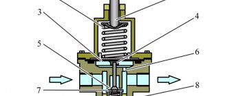
Kinematic diagrams of jaw crushers
1 a. In simple motion crushers (SMMC), the working surface - “cheek” (1) is suspended on an axis (2) and moves along a circular arc. The motion impulse is transmitted through the shaft (3), connecting rod (4) and spacer plates (5). Grinding is carried out by crushing, as well as (partially) breaking and splitting due to the presence of longitudinal corrugations on the crushing surfaces.
1 b . ShchDS crushers (with a complex trajectory of movement) have a simpler kinematic diagram. The shaft (3) is directly connected to the connecting rod, which is also a movable “cheek” (1). The latter rests with its lower end on the spacer plate. This design provides a complex ellipse-like motion path and enables grinding by crushing and grinding. This allows the use of ShchDS crushers for working with viscous materials.
Comparison . At the same rotational moments, higher loads on the material are created on the SHDP crushers, which makes it possible to crush larger and stronger pieces. ShchDS equipment cannot be used for such crushing, but its design is more simple and less metal intensive. The mechanism of movement of the “cheek” can be lever, cam or hydraulic transmission. The latter is shown in Figure 1c.
Crushers with a simple movement of the movable jaw (SMJ).
The crusher with a simple movement of the movable jaw is installed on a frame, in the side walls of which the main bearings of the eccentric shaft are fixed. A connecting rod is suspended from the eccentric part of the shaft. At the bottom of the connecting rod there are grooves for installing the support blocks of the spacer plates. When the eccentric shaft rotates, the connecting rod receives a rocking motion, which is transmitted to the movable cheek using spacer plates. The cheek receives a pendulum movement centered on the suspension axis. Fixed and movable crushing plates are fixed on the cheeks.
The width of the exit slot is adjusted by installing additional spacers of varying thickness between the stop and the rear wall of the frame, a system of wedges on screws, or replacing the rear spacer plate with a longer or shorter one.
The advantages of crushers with a simple swing of the jaw are: the ability to crush high-strength rocks and relatively little wear of the crushing plates. The disadvantage is the high metal consumption compared to crushers with complex jaw swing, as well as the greater unevenness of the resulting fraction.