Pressure regulator device
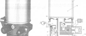
The schematic diagram of the pressure regulator is shown in the figure.
A spring 1 is installed in the valve body, the preload of which is adjusted by screw 2. The spring, through the membrane 3 and the pusher 4, acts on the seat valve 7, which is affected by the spring 8 in the opposite direction.
The outlet pressure depends on the size of the gap between valve 7 and seat 5; in addition, it acts on membrane 3 through channel 6.
The presented valve has two channels, inlet and outlet, which is why it is called two-line .
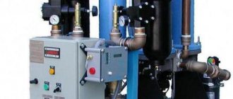
Pressure regulator with filter
This device combines a pressure reducing valve and a filter that cleans compressed air from impurities, dirt particles, and dust. More information about the design and operating principle of such a regulator (RDF) can be found here https://izpk.ru/reduktor-rdf-3-1-rdf-3-2.
Design and principle of operation of the automation unit
To maintain the pressure in the receiver at a certain level, most air compressors have an automation unit, a pressure switch.
This piece of equipment turns the engine on and off at the right time, preventing the compression level in the storage tank from being exceeded or too low.
The pressure switch for the compressor is a unit containing the following elements.
- Terminals. Designed for connecting electrical cables to relays.
- Springs. Installed on adjusting screws. The pressure level in the receiver depends on the force of their compression.
- Membrane. It is installed under the spring and compresses it under the action of compressed air.
- Power button. Designed to start and force stop the unit.
- Connection flanges. Their number can be from 1 to 3. The flanges are designed for connecting the compressor start relay to the receiver, as well as for connecting a safety valve with a pressure gauge to them.
How does a pressure regulator work?
In the initial state, gas enters the valve inlet, flows in the gap between the seat and the valve, and enters the outlet. The amount of clearance is determined by the degree of spring preload, which is changed using an adjusting screw. It turns out that the outlet pressure depends on the inlet pressure and the size of the gap between valve 7 and seat 5.
If the outlet pressure increases, then under its influence the membrane will move and compress the spring, which, in turn, will move valve 7, and the flow area will decrease. The pressure loss across it will increase, which will cause the pressure in the discharge line to drop to the setting value.
If the pressure at the outlet of the regulator drops below the set value, the pressure with which the gas acts on the membrane will decrease, as a result, the preload of spring 1 will decrease. Valve 7 will move and increase the flow area. Losses on it will decrease, which will cause the pressure in the discharge line to increase to the setting value.
How does a regulator maintain pressure at a constant level?
It turns out that the pressure in the outlet line is maintained at a constant level due to changes in the amount of losses on the regulator. The regulator is adjusted using an adjusting screw, which changes the preload of spring 1; the control effect on the valve through the membrane is exerted by the gas pressure from the discharge line.
The regulator outlet pressure is defined as the difference between the inlet pressure and the pressure loss across the valve.
Disposal of coolant is free.
Heating by fuel type
Heating by house type
By source type
Choosing a heating system for heating a private home
If there is no gas on the site and in your area and little electricity power, then you can consider geothermal or solid fuel heating . If your site and budget allow, then it is best to make geothermal heating using a heat pump. The payback period for such heating is approximately four years.
The most budget option is solid fuel heating . The downside here is that you need to constantly monitor the presence of fire and fuel. Also, if there is no gas and the power of electricity allows, then you can consider heating with electricity. The disadvantage of such heating is that it is quite expensive and if there is a line failure in your area, you will be left without heating for some time. Gas heating is the most common type of heating in our region; the clear advantage here is its relatively low price. As a result, no matter what conditions we start from initially, there is always an option to provide your home with heat.
Which of the presented systems is more efficient, cost-effective and reliable is difficult to answer right away. These operational characteristics are determined by a large number of different factors, the most significant of which are the area of the heated room and the financial capabilities of the customer.
Three-line pressure regulator
The design of this regulator differs from the design of a two-line regulator by the presence of a hole in the membrane, which opens if the pressure exceeds a critical value. Under normal conditions, the regulator works the same as a two-line regulator.
If the outlet pressure increases to a value sufficient to move the diaphragm to its highest position and open the relief channel. The gas is released into the atmosphere through this channel. The pressure in the discharge line is reduced until the spring force is sufficient to close the relief channel.
Since excess pressure is released into the atmosphere, three-line regulators of the presented design are used to regulate air pressure.
Thus, the principle of operation of the gas pressure regulator is similar to the principle of operation of the hydraulic pressure reducing valve shown in the video.
Source
Operating principle
The direct acting pressure regulator operates without an auxiliary power source to reduce and regulate high pressure.
A pressure reducer of compressed air supplied to the system inlet allows the outlet pressure to be reduced to a predetermined level without auxiliary energy. The device is a proportional regulator, directly controlled to regulate the pressure of liquid, gas and vapor media.
The output air pressure of regulators-reducers is regulated within a certain range. In its narrowest place you can set the output pressure with the greatest accuracy. The valve remains fully open if there is no pressure.
Engineering communications service Heating, water supply, drainage, sewerage systems
24 hours a day tel: 8
INSTALLATION, REPAIR, MAINTENANCE, MODERNIZATION, REPLACEMENT
The working medium passes from the entrance to the housing and is directed to the exit. Downstream of the valve, at a minimum distance of 10 diameters (or 1 meter), pressure is selected, which is supplied to the actuator through the control line.
Pressure regulator device
The schematic diagram of the pressure regulator is shown in the figure.
A spring 1 is installed in the valve body, the preload of which is adjusted by screw 2. The spring, through the membrane 3 and the pusher 4, acts on the seat valve 7, which is affected by the spring 8 in the opposite direction.
The outlet pressure depends on the size of the gap between valve 7 and seat 5; in addition, it acts on membrane 3 through channel 6.
The presented valve has two channels, inlet and outlet, which is why it is called two-line.
Adjustment and commissioning process
The device is configured and adjusted at the manufacturer's factory. Typical values are 2.8 atm. for the upper limit and 1.4 for the lower limit. However, sometimes situations arise in which it is necessary to adjust the device yourself:
- Setting up after partial or complete repair.
- Specific requirements of consumer devices.
- Installing a relay that was not originally designed to work with this compressor.
Before you begin adjustment, you should carefully study the parameters of all mating devices according to their data sheets. Passport data must correspond to the numbers embossed or engraved on a plate attached to the body of the unit.
The main indicator is the maximum pressure for which the compressor is designed. The value at which the pressure switch will operate should be 0.4-0.5 atm less than this maximum. In real operating conditions of the device, taking into account voltage instability, losses in seals, and the degree of wear of the piston group, this pressure may not be achieved. Then the pressure switch will not turn off the motor, the compressor will work continuously, overheat and wear out.
Having decided on the parameter values, you can begin making adjustments. To do this you need:
- Remove the casing.
- Two nuts will become available - a larger one and a smaller one. These are the regulatory bodies. Arrows are engraved on the body nearby, showing the direction of rotation to increase and decrease the parameter, respectively.
- The large nut sets the value at which the electric motor turns off. When rotated clockwise, the value increases, in the opposite direction it decreases. It is indicated by the P (Pressure) icon.
- The smaller nut sets the difference in engine start pressure compared to the shutdown value. It is designated ΔР.
Before you start setting up, you should fill the tank at least 2/3 full. The sequence of actions is as follows:
- Disconnect the unit from the network.
- Adjust the P and ΔP values by rotating the adjusting nuts.
- The set values should be monitored using a pressure gauge.
A number of manufacturers place adjustment controls on the outside of the device. This increases the convenience of adjustment, but at the same time increases the risk of changing the settings by accidental touch.
How does a pressure regulator work?
In the initial state, gas enters the valve inlet, flows in the gap between the seat and the valve, and enters the outlet. The amount of clearance is determined by the degree of spring preload, which is changed using an adjusting screw. It turns out that the outlet pressure depends on the inlet pressure and the size of the gap between valve 7 and seat 5.
If the outlet pressure increases, then under its influence the membrane will move and compress the spring, which, in turn, will move valve 7, and the flow area will decrease. The pressure loss across it will increase, which will cause the pressure in the discharge line to drop to the setting value.
If the pressure at the outlet of the regulator drops below the set value, the pressure with which the gas acts on the membrane will decrease, as a result, the preload of spring 1 will decrease. Valve 7 will move and increase the flow area. Losses on it will decrease, which will cause the pressure in the discharge line to increase to the setting value.
How does a regulator maintain pressure at a constant level?
It turns out that the pressure in the outlet line is maintained at a constant level due to changes in the amount of losses on the regulator. The regulator is adjusted using an adjusting screw, which changes the preload of spring 1; the control effect on the valve through the membrane is exerted by the gas pressure from the discharge line.
The regulator outlet pressure is defined as the difference between the inlet pressure and the pressure loss across the valve.
Three-line pressure regulator
The design of this regulator differs from the design of a two-line regulator by the presence of a hole in the membrane, which opens if the pressure exceeds a critical value. Under normal conditions, the regulator works the same as a two-line regulator.
If the outlet pressure increases to a value sufficient to move the diaphragm to its highest position and open the relief channel. The gas is released into the atmosphere through this channel. The pressure in the discharge line is reduced until the spring force is sufficient to close the relief channel.
Since excess pressure is released into the atmosphere, three-line regulators of the presented design are used to regulate air pressure.
Thus, the principle of operation of the gas pressure regulator is similar to the principle of operation of the hydraulic pressure reducing valve shown in the video.
Possible causes of failure
Possible causes of failure of the fuel pressure regulator include:
- The car was idle for a long time, and the fuel system was not used;
- Water has gotten into the fuel (condensation is natural under some operating conditions);
- The spring has weakened;
- The membrane is damaged;
- The check valve is stuck or worn;
- The car owner does not change the fuel filters on time;
- The driver fills in low-quality fuel (the valve becomes clogged).
If there is any suspicion of a malfunction of the fuel regulator, it must be checked. As we have already said, for this you can use a simple pressure gauge (even the one used to measure the pressure in tires will do).
Household and commercial pressure regulators in gas pipelines
The structural, functional and ergonomic design of shut-off valves ultimately comes down to the requirements of a specific application. The emphasis is on direct operating parameters, including output pressure, measurement ranges, flow rates, etc. Thus, gas pressure regulators for household networks are usually characterized by low throughput and a modest range of customization options. On the other hand, such fittings focus on safety and ease of use. In practice, household regulators are used in gas supply systems for boilers, stoves, burners and other home appliances.
Industrial and commercial applications place greater demands on gas control equipment. Devices of this type are distinguished by expanded ranges of output and input pressures, accuracy of settings, higher throughput and the presence of additional functions. Similar models are used by gas services that control the supply of social facilities, public catering, industry, engineering, etc. It has already been noted that there are different regulators in terms of the complexity of the design. But this does not mean that in the industrial sector, for example, only multifunctional combination devices are used. Simple controls can be useful in enterprises due to their high reliability and maintainability.
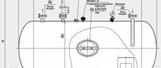
Characteristics of RDUK regulators
| Throughput at a pressure drop of 10,000 Pa and a density of 1 kg/m, m3/h | Diameter, mm | Pressure, MPa | ||
| conditional passage | cla sir | maximum input | final | |
| 300 | 50 | 35 | 1,2 | 0,0005-0,06 |
| 610 | 100 | 50 | 1,2 | 0,0005-0,06 |
| 1000 | 150 | 70 | 1,2 | 0,06-0,6 |
| 2200 | 200 | 105 | 1,2 | 0,0005-0,06 |
| 3200 | 300 | 140 | 0,6 | 0,06-0,6 |
Gas reducer with pressure regulator
A reducer is an autonomous device designed to control the pressure of a gas mixture at the outlet of a container or pipeline. The main classification in this case involves the division of control units according to the principle of operation. In particular, there is a distinction between inverse and direct devices. A reverse-acting reducer works to reduce pressure as gas escapes. The design of such devices includes valves, chambers for buffering the mixture, an adjusting screw and fittings. Direct acting means the regulator will work to increase pressure as gas is released.
Reducer models are also distinguished by the type of gas served, the number of reduction stages and place of use. For example, there are gas pressure regulators for cylinders, pipeline networks and ramps (burners). In the case of cylinders, the type of gas will also determine how the device is connected. Almost all models of gearboxes, except acetylene ones, are connected to cylinders using union nuts. Devices working with acetylene are usually fixed to the container with clamps with a stop screw. There are also external differences between the gearboxes - this can be color markings and information about the working mixture.
Areas of application
The purpose of the pressure regulator is to work as a direct-acting proportional reducer without an additional power source. The device reduces and regulates high inlet pressure, lowering the outlet pressure of water vapor, liquids, compressed air and neutral gases. As the pressure increases, the valve closes because the decreasing pressure is regulated after it.
Similar services:
- Gearbox for load-lifting equipment: purpose and application featuresGearbox for load-lifting equipment: purpose and application features Some mechanisms and machines require equipment with geared motors during their operation. Manufacturing.
- Pressure regulator Any pipeline or system operates under a certain pressure. Exceeding this parameter or lacking it negatively affects their performance.
- Areas of application of diesel fuelDiesel (diesel fuel) is used to operate internal combustion engines. The main consumer of diesel fuel is the transport industry: railways; motor transport; agricultural industry.
- Polymer-coated pipes - main advantages and areas of applicationPolymer pipes have a unique lightness, long service life and very low price, and thanks to these qualities they have begun to intensively replace steel pipes.
- Types and areas of application of food grade stainless steel This material is widely used in industrial production, which is achieved due to its high quality and versatility in use. Types and applications.
- Geogrid: areas of application and advantages Geogrid is a material of synthetic origin. It has a cellular structure. The structure is made from polyethylene, polyester, polyamide and polyester, as well as from...
- Installing a water pressure reducer In order for the water pressure in the water supply system in the apartment to be uniform, it is necessary to install a water pressure reducer (regulator). Purpose of the pressure reducer.
- Technological features and scope of application of heat generators Modern heating units are designed to effectively warm up the air flow before it is supplied to the room. Use of high-quality heating systems.
- HEATING, VENTILATION AND AIR CONDITIONING ► Scope These building codes apply to the design of heating, ventilation and air conditioning systems in buildings and structures (hereinafter referred to as buildings).
- Areas of application of tubular electric heaters (TEHs) The tubular electric heater was invented and patented in America in the mid-19th century by George B. Simpson. Then the heating element was metal.
- Features of the use of HDPE pipesPipes made from low-density polyethylene are inert to chemical influences. They are not subject to corrosion and are characterized by high strength. Pipes.
- Features of gasoline jackhammers and the principle of their operation Today, there are three types of jackhammers on the tool market - pneumatic, electric and gasoline. It is believed that the petrol version is bought less.
- Strip foundation: monolithic, prefabricated (block), rubble, brick - features and scope of application The most popular foundation in private construction is strip foundation. This is one of the most flexible foundations that can be designed for any building.
- How to lubricate the gearbox of an angle grinder? It is no secret that in the construction industry, angle grinders (or...
- How garage doors work, how to install them, equipment features Buying garage doors. This is an important investment not only for practical reasons, but also for thermal insulation and aesthetics. If you are looking.
- Review of the Apex pool dehumidifierThe APEX dehumidifier is highly efficient equipment, the manufacturer of which, taking into account the latest trends in modern technologies, creates devices of high quality and performance.
- Concrete and its scope of application Concrete is a classic of the “construction genre”. Due to the diversity of its properties, this building material is today widely used in the construction of a wide variety of structures.
- Pumping stations: features of choice and types Pumping station is special equipment, the purpose of which is to supply wastewater coming from the house directly into the treatment plant. These devices are commonly used.
- Hormann automatic gates: types and their features. Pipes should be laid and joints sealed in accordance with the instructions in the chapter.
- Pressure switch model FF 4-4 single-pole 0.22-4 bar RUR 5,800 pcs. LLC DESIGN PRESTIGE Product code 214551 LLC DESIGN PRESTIGE works around the clock, travel throughout Moscow and the Moscow region Heating services.
Static and astatic regulators
In static systems, the nature of regulation is unstable in places of direct mechanical interface with the working environment and shut-off valves. In order to increase the stability of such a regulator, additional feedback is introduced to equalize the pressure values. Moreover, it should be noted that the actual pressure value in this case will differ from the standard value until the nominal load on the sensitive element is restored.
The traditional design of a static gas pressure regulator includes its own stabilizing device in the form of a spring - for comparison, other versions use a compensating weight. During the working moment, the force that the spring develops must correspond to the degree of its deformation. The highest degree of compression is achieved in situations where the membrane completely covers the regulatory channel.
Astatic regulators independently bring the pressure indicator to the desired value under any load. The position of the regulatory organ is also restored. However, the executive mechanics, as a rule, does not have a clear position - at different moments of regulation it can be in any position. Astatic control devices are more often used in networks with a high ability to self-level operating parameters.
Types of pressure switch devices
There are two main versions of the device available. The pneumatic-mechanical part is identical; the difference is determined by the method of closing the contacts when the rod moves:
- Normally closed (NC). used for direct control of low and medium power motor circuits.
- Normally open (NO). The movement of the rod closes the contacts when the maximum pressure is reached. The reverse movement opens them as it decreases. The contacts are used to control a more powerful relay that starts and stops the electric motor. The circuit turns out to be more complex, but the load on the pressure switch contacts is reduced and the service life increases.
When replacing a relay, you must carefully check that its type matches the electrical circuit of the compressor. his type.
Isodromic gas regulator
If a static pressure control system can be characterized as a model with rigid feedback, then isodromic devices interact with elastic elements for restoring characteristics. Initially, at the moment of recording a deviation from a given value, the regulator will take a position that corresponds to a value proportional to the deviation from the norm. If the pressure does not normalize, the gas fittings will shift towards compensation until the indicators return to normal.
From the point of view of the nature of operation, the isodromic regulator can be called an average device between astatic and static models. But in any case, there is a high degree of independence of this regulatory mechanics. There is also a type of isodromic reinforcement with advance. This device is distinguished by the fact that the displacement speed of the actuator initially exceeds the rate of pressure change. That is, the technique works proactively, saving time on restoring the parameter. At the same time, regulators with pre-feeding consume more energy from an external source.
Design Features
The gasoline pressure regulator is one of the few elements of the system that is not controlled from an electronic unit. This unit is completely mechanical and its operation is based on pressure differences. Although in systems without recirculation, the sensor is triggered by the ECU. Since they do not occur often, we will not consider such nodes further.
It is worth noting that the RTD does not operate in strictly specified values, it adapts to the operating mode of the engine. That is, if necessary, it increases or decreases the pressure in the system to ensure optimal mixture formation.
Structurally, this element is very simple and consists of a housing on which fittings and leads are located for connection to the power system. Inside, this housing is divided by a membrane into two chambers - fuel and vacuum.
There are outlets suitable for the fuel cavity - one is used to supply fuel to the chamber, and the second leads to the line for draining gasoline into the tank (return). But the second channel is closed by a valve, which is connected to the membrane.
A spring is installed on the side of the vacuum cavity, which acts on the membrane, ensuring that the drain channel is closed by the valve. This chamber is connected to the intake manifold by means of a fitting via a tube.
How to install
Installation of a pressure regulator in a water supply system must be carried out according to certain rules:
- Installation is only possible in a heated room with free access to the device (for the purpose of its further maintenance).
- The body of the device must be solid and not deformed.
- Installation on the pipe is carried out strictly in the arrow direction of the working medium.
- The pipes must be cleaned before installing the pressure regulator.
- To maintain the system, a valve must be installed.
The gearbox is installed in the apartment step by step:
- First, turn off the water in the riser.
- Then an inlet valve is placed on the pipe between the ball valve and the meter.
- A large particle filtration system is installed behind the meter.
- The regulator is installed on a horizontal section of the pipe in the direction of the arrow on the body.
- Next, all joints are sealed.
- And they adjust the location of the pressure gauge for a better view of the dial.
- The last step is to connect the pressure regulator to the ball valve and check the functionality of the system.
If the gearbox is installed not in an apartment, but in a private house, then it should be installed directly behind the meter. And the filter, tap and check valve are behind it.
Tips for choosing regulators
When selecting a pressure regulator, you need to pay attention to its technical characteristics, such as:
- Bandwidth. This parameter for household models should be 0.1-0.15 m3/hour, for commercial models - from 0.2 to 0.3 m3/hour. For large highways and industrial systems, it is recommended to choose products with a throughput capacity of more than 0.3 m3/hour.
- Permissible pressure loss. For domestic needs, the normal loss rate is from 1 to 2.5 Bar, with average water consumption - from 2 to 5 Bar, with high water consumption - from 4 to 7 Bar.
- Bore diameter, in inches. Depends on the purpose of use - household, industrial. In the first case, the figure is ½-¼ inches, in the second - from ¾ to 2 inches.
- Connection method. Coupled, flanged. Both options allow you to create a detachable connection.
It is also worth paying attention to the manufacturer - it is better to choose a regulator from a reliable brand than the cheapest one. The most reliable and widespread brands on the Russian market are VALTEC, HONEYWELL, ICMA, AQUASFERA, WATTS, FADO. They produce high-quality engineering and communications products, characterized by stable technical parameters and a long service life.
Controller operation in different modes
If we take a simplified look at the operating principle, it is quite simple. The pump pumps fuel into the ramp, from which it also enters the fuel chamber of the regulator. As soon as the pressure force exceeds the spring stiffness, the membrane begins to move towards the vacuum cavity, dragging the valve with it. As a result, the drain channel opens and part of the gasoline flows into the tank, while the pressure in the ramp drops. Because of this, the spring returns the valve with the membrane to its place, and the return channel closes.
But as already mentioned, the RTD adapts to the operating mode of the motor. And it does this due to the vacuum in the intake manifold. The greater this vacuum, the stronger its effect on the membrane. Essentially, the vacuum created creates an opposing force against the spring.
In reality, everything looks like this: to operate the engine at idle speed, an increase in the amount of fuel is not necessary, and therefore no increased pressure is required.
In this operating mode, the throttle valve is closed, so there is not enough air in the intake manifold and a vacuum is created. And since the vacuum chamber is connected to the manifold by a pipe, a vacuum is created in it. Under the influence of vacuum, the membrane presses on the spring, so less gasoline pressure is needed to open the valve.
Under load, when the throttle valve is open, there is practically no vacuum, which is why the membrane does not participate in creating force on the spring, so more pressure is required. Thus, this element functions in the power system depending on the operating mode of the motor.
Source
Malfunctions and repairs
Main malfunctions and repairs of the regulator:
- If air leaks from the atmospheric outlet, the valve body must be cleaned or the defective valve and O-ring must be replaced.
- The device has stopped switching the compressor to idle mode. This problem can be caused by a clogged channel, pinching of the piston, or damage to the cuff. It is recommended to clean the valve, conduct an external inspection of the cuff and, if necessary, replace it with a new one, and also update the piston.
- The regulator stopped switching the compressor to the mode of filling the system with air. This malfunction is associated with clogged atmospheric orifice and intake valve, damaged spring, worn O-ring, tight piston part and worn valves. It is necessary to conduct an external inspection of the entire system for damage and defects, and if necessary, replace failed spare parts.
- Air leakage through the outlet into the atmosphere can be eliminated by replacing the filter element.
- When there is no supply of compressed air flow to the brake system of a vehicle, it is necessary to clean the check valve from accumulated contaminants or replace it if worn.
- If there is a small shaft between the on- and off-pressure level of the regulating device, damaged cuffs and rings should be replaced, valves and seats should be inspected and cleaned.
All repair work is carried out only with the engine switched off.
Gas pressure regulators (reducers)
Introduction
A gas pressure regulator (reducer) is a special device that is used to reduce the pressure of gas or various types of gas mixtures in containers (usually cylinders and gas pipelines) to an operating level. Also, such reducers can also be used to automatically maintain pressure at a constant level, regardless of changes in the level of gas pressure in the container.
Gearboxes are used almost everywhere where gas equipment is involved, be it devices operating on flammable (methane, hydrogen, etc.) or inert (nitrogen, helium, etc.) gases. A typical household example is a gas cylinder reducer, also known as a "frog".
Motorists who have equipped their cars with economical gas equipment are also familiar with this device. Liquefied (or compressed) gas in such systems is also first sent to the propane-butane mixture (or methane) reducer, and then enters the carburetor or injector.
The gas reducer is also used in industry. In areas of transition from large highways to local networks, a significant reduction in pressure is required. Powerful and large-sized gearboxes are used here.
Figure No. 1. Diagram of the pressure regulator operation.
The figure schematically shows a gas reducer. All gearboxes are designed similarly. The only differences are in the size of the parts, their design, hole diameters and membrane area. The diagram shows a membrane (1), a spring (2).
When the pressure in the lower part of the gearbox (under the membrane) is below the nominal pressure, the washer (3) on the membrane and the rocker arm (4) pivotally connected to it are lowered, the inlet hole is open. Gas comes from the inlet pipe. When the pressure reaches the required value, the washer and rocker arm rise and close the inlet valve. The pressure at which this occurs is determined by the area of the diaphragm, the elasticity of the spring and, to some extent, the force that must be applied to close the intake valve.
In the diagram shown, the membrane is pressed by a spring. The upper chamber is connected to the environment through a hole. There are sealed modifications of gearboxes in which there is no upper hole and no spring. In them, the space above the membrane is filled with an inert gas under pressure, which ensures elasticity.
Finally, proportional flow valves use a combination of spring and gas pressure. In this case, there is an upper hole, but it is connected by a tube to the area where gas needs to be supplied. Thus, a dependence of the pressure of the supplied gas on the pressure in the place where it is supplied is achieved (proportional supply).
One of the important parameters of the reducer is the maximum gas flow. This parameter is determined by the diameter of the inlet valve opening, since this diameter determines how much gas at a given inlet pressure the reducer will allow through when the valve is fully open. Making this hole too large, as you will see below, does not work. So you always need to make sure that the reducer can provide sufficient flow for your purposes.
Diagrams for connecting the pressure switch to the compressor
The connection of the relay that controls the degree of air compression can be divided into 2 parts: the electrical connection of the relay to the unit and the connection of the relay to the compressor through the connecting flanges. Depending on which motor is installed in the compressor, 220 V or 380 V, there are different connection diagrams for the pressure switch. I am guided by these diagrams, provided that you have certain knowledge in electrical engineering, you can connect this relay with your own hands.
Connecting the relay to a 380 V network
To connect the automation to a compressor operating from a 380 V network, use a magnetic starter. Below is a diagram of connecting automation to three phases.
In the diagram, the circuit breaker is indicated by the letters “AB”, and the magnetic starter by “KM”. From this diagram it can be understood that the relay is set to a switch-on pressure of 3 atm. and shutdown - 10 atm.
Connecting the pressure switch to a 220 V network
The relay is connected to a single-phase network according to the diagrams given below.
These diagrams indicate various models of pressure switches of the RDK series, which can be connected in this way to the electrical part of the compressor.
Connecting the pressure switch to the unit
Connecting a pressure switch to a compressor is quite simple.
- Screw the pressure switch onto the receiver pipe using its central threaded hole. For better thread sealing, it is recommended to use fum tape or liquid sealant. The relay can also be connected to the receiver through a reducer.
- Connect a relief valve to the smallest output from the relay, if present.
- The remaining outputs from the relay can be connected to either a pressure gauge or a safety relief valve. The latter is installed without fail. If a pressure gauge is not required, then the free output of the pressure switch must be plugged with a metal plug.
- Next, wires from the electrical network and from the engine are connected to the sensor contacts.
After the complete connection of the pressure switch is completed, it is necessary to configure it for proper operation.