GAZ-33081, GAZ-33088. ANTI-LOCK BRAKE SYSTEM
A schematic diagram of the braking system of cars with ABS is shown in Fig. 8.4.
The car is equipped with an anti-lock brake system (ABS). ABS is effective during emergency braking on roads with different surfaces (for example, asphalt - ice) and prevents blocking of wheels located in less favorable traction conditions (on ice), providing a minimum braking distance for the vehicle for a given road surface (ice) while maintaining its stability and controllability.
To obtain the optimal effect when emergency braking a car using ABS, you must press the brake pedal with maximum force while simultaneously pressing the clutch pedal.
The electrical part of the ABS consists of 4 ABS sensors (in the wheel units of the car), 3 modulators (on pneumatic amplifiers), a control unit (CU)
ABS (in the cab on the right side panel), ABS fuse block (inside the instrument panel, behind the plug located below the fuse block plug), ABS diagnostic button (on the instrument panel), ABS malfunction indicator (in the right warning lamp block) and ABS wiring harness , connecting sensors and modulators to the ABS control unit.
The ABS malfunction indicator comes on for approximately two seconds each time the instruments are turned on, and then goes off, which confirms that the ABS system is working properly. If the warning light is constantly on, or if it comes on while driving, it indicates a malfunction of the ABS. It is permissible for the indicator to turn on briefly when starting the engine. When the front axle is turned on, the ABS does not work, as indicated by the warning light being on.
If the ABS malfunctions, the vehicle must be checked at a service station.
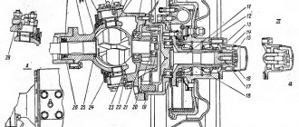
Rice. 8.4. Schematic diagram of the working brake system of cars with ABS: 1-compressor; 2-master cylinder reservoir; 3-brake fluid emergency level sensor; 4-air filter; 5-brake mechanism of the rear wheel; 6-oil pressure sensor; 7-pneumatic brake signal switch; 8-silencer; 9-condensate drain valve; 10-braking mechanism of the front wheel; 11-emergency air pressure sensor; 12-air cylinder; 13-check valve; 14-valve protective single; 15- pneumatic booster with main cylinder; 16-modulator; 17-control valve; 18-air cylinder; 19-air dryer; 20-piston emergency stroke sensor; 21 two-section brake valve with lever
Domestic GAZ-3306/33081/3309 cars use a traditional braking system with original solutions. One such solution is a brake booster based on a vacuum pump. Read about what a vacuum pump is, how it works and works, as well as its maintenance.
How to bleed brakes on gas 3309
A schematic diagram of the braking system of cars with ABS is shown in Fig.
8.3. The vehicles are equipped with an anti-lock braking system (ABS). ABS is effective during emergency braking on roads with different surfaces (for example, asphalt-ice) and prevents blocking of wheels located in less favorable traction conditions (on ice), providing a minimum braking distance for the vehicle for a given road surface (ice) while maintaining its stability and controllability.
To obtain the optimal effect when emergency braking a car using ABS, you must press the brake pedal with maximum force while simultaneously pressing the clutch pedal.
The electrical part of the ABS consists of 4 ABS sensors (in the wheel units of the car), 3 modulators (on pneumatic amplifiers), an ABS control unit (CU) (in the cab on the right side), an ABS diagnostic button (on the instrument panel), and an indicator malfunction of the ABS (in the right block of warning lamps) and the ABS harness connecting the sensors and modulators to the ABS control unit.
Two power circuits are connected to the ABS control unit: for the modulators through the 3rd 25A fuse in the ABS fuse block and directly for the ABS control unit through the 1st 5A fuse in the ABS fuse block. The air dryer is powered through the 2nd 10A fuse. The ABS fuse block is located behind a plug located below the fuse block plug.
Rice. 8.3 . Schematic diagram of the brake system of cars with ABS:
1 compressor 2 – air dryer with pneumatic regulator 3 – regeneration air cylinder 4 – dual-circuit safety valve 5 – air pressure drop sensor 6 – air cylinder 7 – condensate drain valve 8 – two-section brake valve with lever 9 – ABS rotor speed sensor 10 – brake mechanism with ABS rotor on the hub 11 – electric pressure gauge 12 buzzer 13 – emergency piston stroke and low brake fluid level indicator 14 – ABS indicator 15 – two-section reservoir 16 – pneumatic booster with main cylinder 17 filter 18 – emergency piston stroke sensor 19 – control valve 20 – ABS modulator 21 – ABS control unit 22 – “STOP” signal activation sensor 23 – pressure gauge sensor 24 – “STOP” signal lamp 25 – brake fluid level drop sensor 26 – muffler
The ABS fault warning light comes on for a few seconds each time the instruments are turned on and then goes off, which confirms that the ABS system is working properly. If the warning light is constantly on or comes on while driving, it indicates a malfunction of the ABS.
If the ABS malfunctions, the vehicle must be checked at a service station.
Filling the hydraulic brake drive with brake fluid for vehicles with ABS
Thoroughly clean the bypass valves on the wheel cylinders from dirt.
Unscrew and remove the cap with the emergency brake fluid level drop sensor from the main cylinder refill tank and fill the drive with brake fluid. It is prohibited to fill the hydraulic drive with brake
liquids not provided for in the lubrication card, mineral oils, and also wash it with gasoline or kerosene.
When bleeding the hydraulic brake system, the air cylinders must be filled with air (pressure - 0.6-0.8 MPa (6.0-8.0 kgf/cm2).
Bleed the hydraulic circuit of the front axle service brake. Remove the cap on the bypass valve of the right front brake wheel cylinder, put on a rubber hose, and lower the free end of the hose into brake fluid poured into a glass container.
Unscrew the bypass valve 1/2-3/4 turn and press the brake pedal several times. Pump the hydraulic drive until the release of air bubbles from the hose immersed in a vessel with liquid stops.
Close the bypass valve while pressing the brake pedal.
Bleed the wheel cylinder of the left front brake, performing the work specified in paragraph. 4 and 5.
Bleed the hydraulic circuit of the service brake of the rear axle of the vehicle.
Carry out the work specified in paragraphs. 4 and 5, in the next sequential
right brake mechanism
left brake mechanism.
Add fluid to the additional tank of the main cylinders to a level 32-35 mm below the upper edge of the tank neck and install the cap with the emergency level sensor. During the performance of work specified in clauses. 4-8, it is necessary to add brake fluid to the master cylinder reservoir, avoiding a “dry bottom” in the reservoir reservoirs, otherwise air will enter the system again. Check the pressure in the air cylinders.
VESKO-TRANS.RU
AutoNews / Reviews / Tests
- Home
- Auto garage
- How to Bleed Brakes on Gas 3309
How to Bleed Brakes on Gas 3309
Gas-car brake system 3309 , 3308, GAZ-33081 Sadko
Cars GAZ 3309 , 3308, GAZ-33081 Sadko is equipped with 3 brake systems:
— control of wear of wheel brake linings through two holes in the brake panels, closed with removable plugs;
— a system that notifies the driver when the parking brake system is applied;
A schematic diagram of the service brake system is shown in Fig. 1.
— Disconnect the air supply hose from the compressor and disconnect the oil supply hose.
— Unwind three nuts and one bolt securing the compressor to the engine and remove the compressor.
— Secure the compressor vertically to crankcase 2 under pressure (see Fig. 3).
- Remove the intake and exhaust valves.
As a pump, it slows down alone, without outside help.
I've used this simple method for years. I will add that when filling an empty system, it is recommended to first.
Problems with brakes, gas 3309.
obstacles with brakes, gas 3309.
— Press the lock ring 10 and the piston pin 9.
— Unscrew the mounting bolts and remove the side cover 12;
— Press pin 15 and pull pin 16, keeping pin 17 from falling.
The brake drive uses three unified master cylinders: one in the hydraulic drive for the front brakes, two. to the back.
— disconnect the hose or pipe from the brake cylinder;
— unscrew the exhaust valve from the cylinder;
— Lubricate the surface of the parts with a thin layer of Litol lubricant.
— Measure the position of the air booster pusher using a caliper.
- Connect the master cylinder to the pneumatic booster, the torque of the nut is 2.4-3.6 kg/cm.
— Attach the mount to the pneumatic module of the amplifier of the modulator cylinder.
The need for replacement is determined by the formation of condensation in the air cylinders. The accumulation of huge amounts of condensate in the pneumatic actuators of the brake drive can lead to their failure.
It is necessary to monitor the condition of the faucet's protective casing and its tightness in relation to the body, since dirt getting on the lever system and the cleaning surfaces of the faucet leads to malfunction.
The freewheel pedal with the service brake valve should be 20-25 mm.
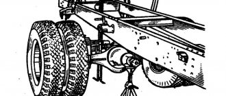
Procedure for removing the gearbox from the car
When starting to dismantle the faulty gear module from the vehicle, the following steps must be taken:
- Measure the ground clearance under the rear axle housing.
- Raise the car with a jack to remove the wheels, and then place the car on fixed supports so that the ground clearance matches the previously measured measurements.
- Drain the oil.
- Disconnect the driveshaft.
- Remove the axle shafts by first disassembling their attachment to the wheel hub.
After completing all the steps, the gear module itself is dismantled by unscrewing the mounting bolts.
To further diagnose the condition of the internal parts, the rear axle gearbox of the GAZ-3307/3309 must be thoroughly washed, first soaked in a washing solution.
GAZ 3309 diesel who has problems with brakes
Hello! I am the owner of GAZ-3309. I heard from many that there is a problem with the brakes (hydro-pneumatic), especially everyone complains about airing the circuits. I think that there are people to whom this problem is very close and there will be experts on this car.
What kind of hydro-pneumatic brakes are these?
This is when the car is tangled with valves and pipes. The point is that a pneumatic chamber is screwed to the main brake. The air presses on the chamber, and the main brake fluid presses on the wheels. There are three main ones on Gaza, two on the back and one on the front. The car has two systems: pneumatic with all taps, valves, and hydraulic. There were these on Pazakh, but they switched to pneumatic ones. The Urals have always had and still have such brakes. I myself worked in the Urals and have never met a worse system.
This is when the car is tangled with valves and pipes. The point is that a pneumatic chamber is screwed to the main brake. The air presses on the chamber, and the main brake fluid presses on the wheels. There are three main ones on Gaza, two on the back and one on the front. The car has two systems: pneumatic with all taps, valves, and hydraulic. There were these on Pazakh, but they switched to pneumatic ones. The Urals have always had and still have such brakes. I myself worked in the Urals and have never met a worse system.
I know it. I work on a lawn like this. but I asked because the brakes there are not called hydro-pneumatic, but pneumatic-hydraulic. There's also ABS there.
Measures to ensure stable operation of gearbox parts
In order for the GAZ-3309 gearbox to operate throughout its entire declared service life, which is 300 thousand kilometers, it is necessary to follow the operating rules and carry out preventive maintenance specified by the regulations, including:
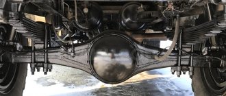
External view of the rear axle GAZ 3309
- Check and change oils regularly according to mileage and load.
- Clean the ventilation valve (breather) prophylactically.
- Monitor the condition of the rear axle for deformation and deflection, which lead to increased wear and destruction of gearbox parts.
- If additional noise appears, eliminate the cause as soon as possible to avoid deterioration of the components.
If these simple rules are followed, the performance of the gearbox will be maintained for the declared service life.
Thus, the rear axle gearbox of the GAZ-3309 is a complex design that requires careful attention, since it directly affects driving safety.
Diagram of the brake system GAZ-3309 diesel
During the design of such a vehicle, the plant's engineers decided to develop its design almost from scratch, which made it unlike other cars of the automaker. The brake system of the GAZ 3309 deserves special mention, which is radically different from its predecessors.
When studying its structure, it is advisable to identify several categories of basic elements that ensure correct operation. These include:
- worker node;
- parking brake equipment;
- spare system.
All of them are designed to quickly brake the truck or slow down its movement. The pneumatic-hydraulic brakes of this vehicle are reliable, which is especially important for freight vehicles, the braking distance of which is critical when dangerous situations arise on the road.
By working unit we mean the main system, which is constantly used while driving, and the spare one is a reserve in case of failure of the first one.
Brake device
Considering the design of this GAZ 3309 system, it should be noted that the standby and backup systems are combined into one set, which should be taken into account when performing repair work. In previous models, the pedal had to be pressed with considerable force to brake, but in the new design, the automaker's engineers managed to completely eliminate this drawback.
The brake design includes the following elements:
- standing brake - clamp, lever-handle, disc, handbrake cable, release element, drum, shoes, related mechanisms;
- drive part - pads, protective caps, pistons, guide brackets, shield, hydraulic cylinder reservoirs, as well as other components;
- brake cylinder - lever body, rod, guide parts, brake light switches.
An important design element is the amplifier, which is designed to increase pressure in key components. Due to this, it becomes possible to significantly increase braking efficiency without the need to exert maximum effort on the controls.
Diagnostics of malfunctions of the gear mechanism of the rear axle of GAZ-3309
The initial diagnosis of the gear unit, as well as the rear axle as a whole, is to determine the presence of extraneous sounds when driving by ear.
Depending on the type and nature of newly appeared sound changes, possible faults can be assessed and localized in advance. You can identify some typical sounds of a faulty gear unit and determine the stages of repair.
View of the rear axle GAZ-3309
- Sound characteristic Cause
- Loud noise coming from the gearbox
- Poor fastening of the drive gear
- Incorrect setting of the nominal distance in the differential module or it has reached the output limit value
- Bearing failure
- Excessive howling at a high pitch,
- accompanied by bridge overheating
This is what the rear axle gearbox looks like
- Reduced lubricant level in the crankcase
- Incorrect installation of internal contacts in the main gears
- Whistling sound Lack of lubrication in the cardan connection module
- Appearance of a noise effect with periodic occurrence
- The driven gear is poorly secured
- Misalignment in the installation of this part
- Continuous grinding and crunching
- Chips in gear teeth
- Bearing failure
- Excessive noise when cornering
- Incorrect operation of the differential module, in particular, satellites
- Violation of the gap setting in the differential module
- Noise when starting to accelerate
- The life of the differential module is exhausted or the gaps are set incorrectly
- Noise when the engine is braking
- Excessive backlash vibrations in the drive gear bearings or their service life.
- The presence of foreign particles in the oil
- Excessive knocking noises when starting to move
- Differential module fault
- Presence of greater clearance in gears
The appearance of these sounds requires immediate repairs, usually accompanied by dismantling the rear axle to remove the gear unit.
External view of the rear axle GAZ 3309
It should be noted that before proceeding with a major overhaul of the mechanism, it is advisable to additionally make sure that the disturbing sound comes directly from this part of the car.
Similar noises can accompany wear on the wheel bearings. To eliminate this possibility, you need to use a jack to hang the rear wheels one by one and spin them. If a characteristic sound appears, replace the hub bearings and re-check the rear axle gearbox of the GAZ-3307/3309 for the presence of extraneous sounds.
It is possible to eliminate some types of sound deviations without resorting to complete disassembly of the module.
Vacuum pump features
An important design element is a vacuum amplifier, which is capable of creating the necessary pressure in the system. Due to this, it is possible to significantly increase braking efficiency, as well as reduce the required force when pressing the pedal. It should be remembered that incorrect operation of this important unit is a dangerous breakdown, leading to unstable operation of the power unit.
This is due to the entry of air into the intake pipe of the engine, which contributes to the leanness of the fuel mixture in its cylinders. As a result, the car cannot operate for a long time and periodically stalls. The design of the system involves the removal of lubricant and mechanical damage to the cylinders in the event of such a malfunction, which is why it is necessary to eliminate it as soon as possible.
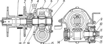
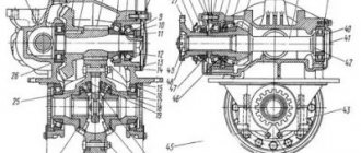
Diagnostics of internal parts of the gearbox
The first step in identifying possible faults is a careful inspection of the parts. It should be noted that in most cases, partial replacement of worn parts is more economically justified than replacing the assembled gear module.
To provide access to all components of the structure, it is necessary to disassemble the removed gear unit completely, while observing the sequence of actions:
- Remove the cotter pins on the nut holding the tail part of the drive gear, unscrew and remove it complete with the washer.
- Remove the flange, then dismantle the cover installed at the front, and also remove the oil ring and seal.
- Next, you need to remove the bearings together with the clutch, and also dismantle the rings, including the adjusting and front tapered bearing.
- Disconnect the driven gear from the differential module by unscrewing the mounting nuts.
- Remove the oil trap by first bending the ring-type stopper and unscrewing the fasteners.
- After removing the remaining bolts, disassemble the differential block into individual components.
Upon complete disassembly of the gear unit, examine the condition of each part for chips, cracks, scuffs and other deviations from the norm. Elements with mechanical damage must be replaced.
The presence of wear on the gear teeth is carefully checked, and the meshing of the teeth of the correct configuration must be ensured with a complete plane. If there is a change in the tooth configuration that prevents full engagement, the gears must be replaced.
Gearbox assembly parts
The condition is also inspected for the presence of the edge of the locking pins; its absence is an indicator of complete wear of the part and, accordingly, its replacement with a new one.
It should also be noted that the bearing pre-installed in the gear mechanism must be changed in any case according to the manufacturer’s recommendations.
After inspection and preparation of new parts, the device must be reassembled in the reverse order. During assembly, you must carefully set all the necessary clearances, guided by the manufacturer’s data.
Adjusting the parking brake
One of the most important jobs when servicing this vehicle is adjusting the parking brake. It is performed in several stages, and the car enthusiast will only need to have the necessary skills, a 24 mm wrench, and a screwdriver.
The hand brake is adjusted using the following algorithm:
- Lower the lever to the lower position and shift the gearbox to neutral;
- Raise the rear wheel on the left side using a jack, then remove the shield plug.
- Rotate it, turning out the adjusting screw with a screwdriver until it slows down, then unscrew the screw until the wheel rotates freely.
- Install the plug, lower the wheel, and then adjust the mechanism on the right side in the same way.
Doing this will help keep your parking brake system in optimal condition, ensuring it operates effectively.
Brake bleeding technique
Many owners of this car are interested in how to properly bleed the brake system for more efficient operation. This is a pressing problem for many models of domestic trucks, the solution of which requires an integrated approach. You can perform such tuning by following the following instructions:
- Clean the valve mechanisms of the cylinders of each wheel.
- Unscrew the cylinder cover.
- Fill it with the fluid recommended by the manufacturer.
- Bleed the front wheels.
- Remove the brake valve cap, install the hose, and place its other end in a container with brake fluid.
- Unscrew the valve half a turn, then depress the brake pedal several times.
- Screw the valve back and bleed the remaining wheels using a similar method.
When filling brake fluid, it is advisable to remember that its optimal level is 2-3 cm below the maximum recommended level.