KAMAZ gearbox device
The gearboxes that KAMAZ vehicles are equipped with are fundamentally no different from similar units of other tractors. However, they are not interchangeable and have certain design features.
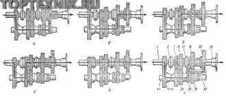
The most common two variants of the KAMAZ gearbox are the 14th (141, 142, 144) and 15th (152, 154) models.
Three shafts are installed in the crankcase of both boxes:
- leading;
- intermediate;
- slave.
Like any modern manual transmission, they are equipped with synchronizers and have a gear transmission. Reverse gears are installed in a separate block. The speed change mechanism is located in a separate block, which is located in the upper part of the box.
Issues of maintenance and repair of the divider gear shift mechanism
The unit in question does not require special maintenance; it is only necessary to periodically check and set the recommended gear shift travel and the gap in the divider switch valve. The procedure for carrying out these operations is prescribed in the operating and repair instructions for the truck. It is important to remember that any adjustments must be made with normal air pressure in the pneumatic system and with the clutch properly adjusted.
If the parts of the mechanism wear out and break, it is advisable to completely replace the complete mechanism (or separately the mechanism and the air distributor). After such a replacement, the above adjustments should be made, and if everything is done correctly, the car will be immediately ready for use.
KAMAZ gearboxes of the 15th model (152 and 154) use an additional single-stage gearbox - a divider, which doubles the total number of gears. The divider is controlled pneumatically using a special mechanism - this mechanism is described in detail in this article.
KAMAZ gearbox divider device
A divider is a mechanism that reduces the gear ratio of a gearbox.
Its design includes the following components:
- synchronizer blocking rings installed on both sides;
- a clutch with teeth that synchronizes the rotation of elements;
- two gears;
- two shafts;
- frame;
- gear shift fork;
- lever arm;
- fork roller.
To reduce wear and increase service life, parts operate in an oil environment.
If you are planning to independently repair a KAMAZ gearbox with a divider, the device diagram should be well studied and be at hand.
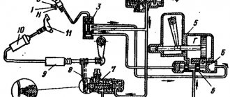
Design and operation of MPPD
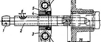
The mechanism consists of a cast case, in which three main parts can be distinguished:
- Box for the fork shaft lever - this box contains the lever and the part of the piston rod connected to it;
- A sealed cylinder in which the piston is located;
- A small diameter cylinder connecting the large cylinder to the box - this is where the piston rod is located.
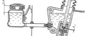
In the lower part, a control unit - an air distributor - is attached to the MPPD housing. It is a tube in which a spool is installed, providing compressed air above or below the piston. On both sides of the spool there are pistons located in sealed cylinders - with their help, the spool is moved when the divider switch on the lever is moved to one position or another. The spool and pistons are part of different circuits of the divider control pneumatic system, so they are sealed to each other.
The mechanism works as follows. When the switch on the lever is moved to the lower position (reduction gear of the divider), the compressed air from the control valve is divided into two circuits and supplied:
- Into the right control cylinder of the air distributor;
- At the input of the divider switching valve.
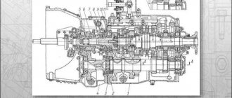
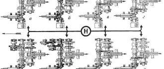
KAMAZ gearbox diagram with divider
| 1 | Nut M12x1.25-6N | 28 | Spring washer 8 |
| 2 | Lock washer 12.3 | 29 | Gear divider housing hatch cover |
| 3 | Front intermediate shaft bearing cover | 30 | Crankcase stud M16x1.5x22x45 |
| 4 | Lock washer 10 | 31 | Spring washer 16 |
| 5 | Bolt M10x1.25-6gx30 | 32 | Nut M16x1.5-6N |
| 6 | Input shaft bearing cover assembly | 33 | Gear divider synchronizer assembly |
| 7 | Input shaft cover gasket | 34 | Gear divider housing gasket |
| 8 | Adjusting gasket | 35 | Gear divider intermediate shaft assembly |
| 9 | Adjusting gasket | 36 | Intermediate shaft rear bearing seat |
| 10 | Gear divider primary shaft assembly | 37 | Screw M6-6gx16 |
| 11 | Special nut M52x2-L-6N | 38 | Roller bearing |
| 12 | Primary shaft oil injection ring | 39 | Upper clutch housing cover |
| 13 | Pin 4x12 | 40 | Gear divider intermediate shaft |
| 14 | Radial roller bearing with long cylindrical rollers, double row, without rings | 41 | Intermediate shaft gear |
| 15 | Retaining ring | 42 | Gear divider with control assembly |
| 16 | Single row radial ball bearing GOST 520-89 | 43 | Pin 12x35 |
| 17 | Gear divider primary shaft | 44 | Hairpin M16x1.5x22x35 |
| 18 | Prismatic key 6x8x13 | 45 | Single row radial ball bearing with a groove on the outer ring |
| 19 | Primary shaft rear bearing bushing | 46 | Front bearing thrust ring |
| 20 | Gear divider input shaft gear assembly | 47 | Thrust washer |
| 21 | Drain plug with magnet assembly | 48 | Hairpin M12x1.25x18x30 |
| 22 | Gear divider housing with bushings assembly | 49 | Locking bar |
| 23 | Oiler KG/8″ 45 (45916751064) | 50 | Bolt M12x1.25-6gx30 |
| 24 | Eye bolt | 51 | Front intermediate shaft bearing cover gasket |
| 25 | Plug 28 | 52 | Bearing cap sealing ring |
| 26 | Pad | 53 | Lower clutch inspection hatch cover |
| 27 | Bolt M8-6gх16 | 54 | Clutch housing cover |
Design and operation of MPPD
The mechanism consists of a cast case, in which three main parts can be distinguished:
- Box for the fork shaft lever - this box contains the lever and the part of the piston rod connected to it;
- A sealed cylinder in which the piston is located;
- A small diameter cylinder connecting the large cylinder to the box - this is where the piston rod is located.
In the lower part, a control unit - an air distributor - is attached to the MPPD housing. It is a tube in which a spool is installed, providing compressed air above or below the piston. On both sides of the spool there are pistons located in sealed cylinders - with their help, the spool is moved when the divider switch on the lever is moved to one position or another. The spool and pistons are part of different circuits of the divider control pneumatic system, so they are sealed to each other.
The mechanism works as follows. When the switch on the lever is moved to the lower position (reduction gear of the divider), the compressed air from the control valve is divided into two circuits and supplied:
- Into the right control cylinder of the air distributor;
- At the input of the divider switching valve.
Under the influence of the force of compressed air, the distributor spool moves to the left, opening access of compressed air to the left cavity of the MPPD cylinder. However, at this moment the divider switch valve is closed, so no switching occurs. When the clutch pedal is depressed, this valve opens, and air under pressure is supplied through the spool into the cylinder - under its action, the piston moves to the right, and its rod pulls the lever, as a result of which a downshift or upshift of the divider is engaged. If the divider switch on the lever is moved up, all processes occur in the reverse order.
The mechanism on which the air distributor is immediately installed is mounted with five bolts (and through a gasket) on the left side of the gearbox housing in the direction of travel of the car.
Issues of maintenance and repair of the divider gear shift mechanism
The unit in question does not require special maintenance; it is only necessary to periodically check and set the recommended gear shift travel and the gap in the divider switch valve. The procedure for carrying out these operations is prescribed in the operating and repair instructions for the truck. It is important to remember that any adjustments must be made with normal air pressure in the pneumatic system and with the clutch properly adjusted.
If the parts of the mechanism wear out and break, it is advisable to completely replace the complete mechanism (or separately the mechanism and the air distributor). After such a replacement, the above adjustments should be made, and if everything is done correctly, the car will be immediately ready for use.
Switching rules under different conditions
Gear changes depend on the various conditions in which the vehicle is moving. These rules should be followed so that during the use of the gearbox it does not fail.
Climb
During an ascent, you must switch the gearbox to mode H, as a result of which the transmission will begin to operate at increased voltage.
The following rules must be followed:
- When switching from 1st to 2nd gear when ascending a KamAZ truck, you must use the method of depressing the clutch pedal twice.
- In order for the crankshaft to work correctly when changing gears, you need to use the fuel pedal; it also needs to be pressed periodically. At the same time, you can overcome any steepest climb.
- The shaft speed when lifting must be more than 2000 rpm. Otherwise, the engine may shut down, which may cause an accident while driving on the road.
- During the climb, switch to the desired mode, this will facilitate the operation of the engine and all components of the machine.
Descent
Some drivers turn off the engine when descending a mountain to save gas. This should not be allowed at KamAZ.
If you turn off the internal combustion engine during a trip, the electric booster will not perform its functions, which will lead to the steering wheel locking.
KamAZ braking occurs not only as a result of stopping the engine, but also by activating the auxiliary braking system. When a heavy vehicle is going downhill and the driver applies the auxiliary brakes, the clutch should not be depressed and the driver should not shift from one gear to another.
Icy areas
You need to drive a truck on icy areas with maximum speed and range. When braking, you must use the engine stop assist system. If emergency braking is required, the operator must stop the trailer wheels. If you do not take this rule into account, you may end up in a skid.
It is possible to slow down the internal combustion engine only as an exception, as this can lead to its wear. When braking, the wheels should not slip. To avoid this, you need to turn off the reduced speed, which will help reduce the rotation of the crankshaft.
Skid
When skidding, do not disengage the clutch. When the truck skids, you need to turn the steering wheel in the direction of the skid. If the KamAZ skids, you need to take your foot off the gas pedal and press the differential. This must be done using the regulator located on the panel. As a result, the indicator on the panel will turn on. You need to start the move from the second high gear. After overcoming the skid, the differential should be unlocked.
Gearbox control
Shift gears in the gearbox using the gear lever located to the right of the driver's seat. Change gears with the clutch disengaged. Press the clutch pedal all the way. Engage and shift gears at minimum idle speed. Start driving only from first gear (to avoid premature clutch failure). To quickly accelerate the vehicle on good roads and in difficult conditions, it is recommended to use all gears sequentially according to gear shift patterns. In cars with a cable drive to control the gear shift mechanism, a gearbox with a servo shift is used. The servoshift serves to facilitate gear shifting; air is supplied to it from the car's pneumatic system.
Attention! Do not change gears until the operating pressure in the pneumatic drive is reached (from 6.5 to 8.0 kgf/cm 2 ) to avoid cable breakage due to the servo shift not developing the required force.
If there is a divider in the gearbox, a gear divider control switch is mounted in the gear shift lever handle (see Fig. Gear shift lever). The switch can be used to select the highest “B” or lowest “H” gear in the divider. It is recommended to use the entire range of low and high gears. To switch from a higher gear to a lower one, and vice versa (without shifting the lever), you need to move the gear divider control switch to the desired position, and then press and release the clutch pedal after a short (1 second) delay - the gear will engage automatically. To simultaneously shift the lever and engage a higher or lower gear, set the divider control switch to the “B” or “H” position, press the clutch pedal and shift the lever.
Gear shift lever
For gearboxes of models 144, 154, shift gears according to the diagrams (see Fig. Gear shift diagram in a model 144 gearbox and Gear shift diagram in a model 154 gearbox).
Shift diagram for a 144 transmission
Shift diagram for a 154 transmission
For the ZF 9S1310 model gearbox, shift gears according to the diagram (see Fig. Gear shift diagram in the ZF 9S1310 model gearbox):
- 1-2-3-4-lower gears (lowest range of multiplier);
- 5-6-7-8-high gears (highest range of range).
When slowing down, change gears only sequentially: 8-7-6-5-4-3-2-1. Always keep the gear engaged when driving.
Gear shift diagram in the gearbox model ZF 9S1310
Low gear “C” is intended for starting in difficult road conditions and for maneuvering.
Attention! For gearboxes it is strictly prohibited:
- switch from the highest range of the multiplier to the lower range of the multiplier at a speed of more than 30 km/h (for ZF gearboxes);
- move with the gear shift lever in neutral position;
- engage reverse gear (R) when the vehicle is not completely stopped and when the clutch plate is rotating.
Gear shifting in the multiplier occurs automatically: the highest gear is engaged when the gearbox control lever moves from the fourth to the fifth position, the lowest gear is engaged when switching from fifth to fourth. When the lever is moved through the “◊” position, the valve is activated, providing automatic switching of the range multiplier. When the low range is turned on in the range multiplier, the warning lamp lights up on the instrument panel
. When the range shifter is switched, the gear shift lever rod of the main box is blocked, and a force is felt on the lever, after which it is recommended to wait 1-1.5 seconds to ensure the gear shift in the range shifter.
How to change gears on KamAZ
To change gears correctly, you need to know how the transmission works. The gearbox is designed in such a way that movement is often carried out at a reduced speed, so the machine can transport heavy loads. KamAZ has a 5-speed gearbox. You need to change gears using the clutch pedal and lever.
Start of movement
Before you start moving, you must press the reduced speed. Shift gears only with the clutch pedal depressed. The gear shift pattern is based on staged gear shifting. To start driving a truck, you need to spin the crankshaft of the internal combustion engine.
The second gear must be engaged when the needle on the tachometer reaches mark 3, which means 3000 rpm. This method of gear shifting will make it possible to extend the life of the gearbox and reduce gasoline consumption.
Switching speeds
Let's consider the procedure for switching gears after the car has already started moving. When KamAZ accelerates, the gear shift order is: 4H - 4B - 5H. To engage speed 2, the crankshaft speed must increase to 3000 rpm according to the tachometer readings. The functions of the crankshaft are basic.
Reverse
To engage reverse on a truck, you need to place the switch in the lower left position. Reverse gear cannot be engaged while the vehicle is moving. To engage reverse, you must first completely stop the unit, then perform a maneuver.