- home
- Media center
- Articles
- Engine ZIL 130 characteristics
Menu
- News
- Articles
- Video materials
- Photo materials
- Publication in the media
- 3D tour
19.08.2020
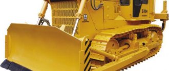
The most popular medium-duty truck of the second half of the last century in our country is the ZIL-130. It was produced at the Likhachev Automobile Plant in Moscow and other car production enterprises in the Soviet Union and Russia. The main reasons for the demand for this vehicle are its reliability, long service life, and maintainability. Unpretentious in operation, the car is capable of operating in any climatic conditions in intensive mode. One of the reasons for its popularity was the engine of the same name, developed at ZIL.
In our review, we will consider the volume of the ZIL-130 engine of this model, the weight of the internal combustion engine of the ZIL-130 car and other important indicators. We will also answer questions about the weight of the power unit of the ZIL-130 truck, how many “horses” are hidden under the hood of this vehicle, what is the power of the ZIL-130 automobile engine.
History of creation
Work on the creation of the truck began in 1953 under the leadership of designer A. M. Krieger. Initially, the car was named ZIS-125, a little later ZIS-150M. The first models of cars in 1956 were equipped with a five-liter power plant with a capacity of 135 horsepower and a maximum torque of 320 N. m. It had a V-shaped arrangement of six cylinders and was equipped with a carburetor. However, this engine was unable to ensure the operation of a medium-duty truck. It lacked the power to create the desired dynamic characteristics.
The following year, the car received a unit with six cylinders, the valves of which are located in the upper part. It was superior to the previous version in power: 140 hp. With. and had a larger working volume: 5.5 liters. However, it also did not pass verification tests. The design team settled on the following option, which turned out to be final. This option was used throughout the entire production period of the truck. The six-liter engine had 150 horsepower and was equipped with liquid cooling. The model for creating this installation for a truck was the “engine” from the ZIL-111 limousine, intended for the USSR government.
The differences between this motor and the sample were in the lower compression ratio - 6.5. This led to a decrease in power - from 220 hp. With. it dropped to 148 hp. With. The class of fuel consumed has also changed. The government limousine consumed expensive gasoline with an octane rating of 95; a work vehicle could not afford such luxury. He was switched to 76 gasoline, which was popular at that time.
Two years after the launch of the series, the plant management modernized the car and engine. During its implementation, the power of ZIL with index 130 increased slightly to 150 “horses”. This value remains until the end of the machine's production period. At the same time, the service life before major repairs was regulated - 200,000 mileage. The next modernization, carried out in 1976, made it possible to increase the service life to 300 thousand km.
The new power unit with the factory index 508 had a good appetite. Its consumption per 100 km ranged from 30 to 40 liters. However, given the fuel prices of those times, such consumption was not critical. As a result, ZIL produced over three million of these units. There were legends about the unpretentiousness in operation and maintenance of this unit. It tolerated the heat of the southern republics of the USSR well; there were no problems with its launch in frosty weather in the northern regions of the country
Note that in 1974, the ZIL 130 medium-duty truck began to be equipped with a more economical engine with less power, the ZIL-157 with 110 “horses” under the hood.
At the turn of the eighties and nineties of the last century, when the political situation in the country changed radically and fuel prices soared, ZIL management made attempts to switch the popular truck to cheaper diesel fuel. But in the end they were unsuccessful. Later, in order to reduce fuel costs, truck owners began to switch to using gas-cylinder equipment.
Ignition principle
To better study the topic of the order of operation of the cylinders of the ZIL-130 engine, you should know how ignition occurs. You should know its order in order to assemble the engine during a major overhaul and when removing the distributor. To install the ignition on a ZIL 130, you must perform the following procedure:
- Correct the piston stroke of the first cylinder, place it next to the compression stroke at the top. To do this, you need to rotate the crankshaft until the hole in the friction ring is at the TDC indicator on the installation indicator. It can be seen on the limit sensor of the maximum permitted number of revolutions.
- Change the position of the shaft groove of the distributor device. This element needs to be parallel to the flange mark at the top. After adjustment, the component should be placed in the block. Before installing the distributor drive, you should ensure that the holes on the bottom flange of the housing correspond to the grooves required for bolting. Then the angle between the axial groove guide and the connecting axis should be approximately 15 degrees.
- Turn the crankshaft when the ignition timing is shifted. To rotate the shaft, use the starting handle. During operation, align the crankshaft hole of the pulley with the radio interference filter in the ignition coil.
- Release the plate fixing bolt. After this, insert the distributor into the socket in the position in which the correction octane faces upward. Place the rotor electrode at the terminal of the first combustion chamber.
- Eliminate gaps in the switchgear. Installing a distributor means removing the tire, turning the camshaft using the slider from left to right, turning on the ignition and turning the housing until the mass with the central wire is ignited. After adjustment, the gap between the end conductor part and the ground should not be more than three millimeters.
- Tighten the bolt that secures the distributor plate. Check wire connections. They should be inserted as required by the order of the ZIL 130 cylinders. Before installing the ignition mechanism, you should check the contact distance of the breaker conductors. If the gap is larger than the normal designations, it should be adjusted in the desired direction. It is important to set the top plate on the octane corrector to O.
As a result, the ZIL-130 engine serves as the standard of the Soviet power engine for a reason. The order of operation of the ZIL cylinders is complex, but well thought out, thanks to which trucks with it move as smoothly, reliably and with the least amount of fuel consumption. The four-stroke eight-cylinder unit with a carburetor fuel supply system is one of the most reliable Soviet-type devices, and therefore remains in demand to this day. For better maintenance and major repairs of equipment, you should carefully study the design features and operating procedure of the engine presented above.
How the motor works
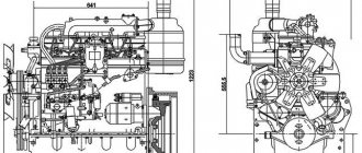
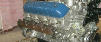
The ZIL unit number 130 received eight cylinders arranged in a V8 format. This means that they are placed at an angle of 90 degrees relative to each other. This arrangement makes the power unit more compact and lightweight, requiring less space for installation under the hood. This arrangement allows you to place attachments on it.
During the operating cycle, the motor makes four strokes. The air-fuel mixture is fed through a two-chamber K-88 carburetor device. The engine capacity produced at the ZIL automobile plant of the 130 series is 5.969 cm3. The operation of the motor is limited by the maximum speed limiter.
Between the rows of cylinders are located:
- fuel supply pump;
- carburetor device;
- air purification filter;
- switchgear breaker;
- oil filter;
- inlet pipeline.
In the front part there is a water supply pump, a compressor device for pumping air, a fan, and also pulleys for the drive.
The crank mechanism is considered the basis of this power plant. The crankshaft and camshaft are connected by gears. The camshaft cams, with the help of auxiliary elements: pushers, rods, force the rocker arms to move, which in turn act on the valves. They return to their previous position due to installed springs.
The K-88 carburetor operates on the falling flow principle and has a balanced float chamber.
Materials
The frame of the structure is made of improved quality cast iron. It has increased resistance to the formation of corrosion foci.
The material for the manufacture of two cylinder heads was an alloy of aluminum with other metals, which enhance the strength characteristics of the housing. Displacers are made of a similar material and are equipped with several rings. The top two, compression ones, are made of cast iron and coated with chrome. The purpose of the compound third is to remove oil. It is made from an alloy of steel and chromium. Hollow, floating fingers are also made of steel.
Let's list the materials for manufacturing the remaining components of the motor:
- connecting rods are made of steel, they have an I-section and lubricate the piston pin;
- liners are made of steel tape and aluminum alloy;
- camshaft - five-bearing, made of steel;
- The crankshaft is forged, steel, and also has five bearings. It is equipped with lubrication channels;
- the flywheel is made of cast iron, the crown that starts the motor from the starter is made of steel.
- The power unit block is equipped with sleeves with sealing rings at the bottom. Let's look at the design of valves. The intakes are driven by the camshaft. They are located in the cylinder head of the engine compartment.
- The exhaust valves of internal combustion engines are hollow and have a heat-resistant overlay. They are equipped with a mechanism for forced rotation.
- The material for the pushers was steel, reinforced on top with cast iron surfacing. The rocker arms are also steel, they are equipped with bronze bushings.
- The intake manifold is made of aluminum alloy and is common to the cylinder banks. The fuel mixture coming from the carburetor is heated through a cavity located between the two heads of the block.
- Two gas outlet pipes are installed on each side of the block, made of cast iron.
Setting TDC at the moment of compression
The problem arises when the piston becomes in the correct position to adjust the valves of the first cylinder. The piston must be at TDC during the compression stroke. There is a mark on the crankshaft pulley. It needs to be aligned with the TDC designation on the scale.
Indeed, the piston of the first cylinder will rise to TDC. But it is necessary to make sure that it is in the compression stroke. Because for the full cycle of engine operation from the first to the eighth cylinder. The piston becomes twice at TDC. We are only interested in one of its positions. This position can be determined in several ways.
- If the engine is in working order on the car. You can remove the tip from the spark plug wire going to the first cylinder. And turn the crankshaft with the ignition on. At the moment a spark jumps between the wire and ground. You should place a mark on the pulley with the TDC designation on the scale. The spark will jump before the piston reaches top dead center. And by setting the marks, the piston will move to the desired position.
- You can unscrew the spark plug of the first cylinder and plug the spark plug hole with a paper plug. When cranking the crankshaft, the plug will shoot out. All that remains is to align the mark on the pulley with the TDC mark on the scale. You can simply plug the hole with your finger. When air starts to come out from under it, all you have to do is align the marks. This indicates that compression is forming in the cylinder. Compression begins. Therefore the valves are completely closed.
- Visually, the TDC position is determined by the rocker arms. In the compression position when the piston approaches TDC, the rocker arms are not movable. The valves are closed. In the second position, when the piston approaches TDC, one valve closes. The second one, after passing TDC, begins to open immediately. If the valves are stationary, all that remains is to align the marks.
After the piston of the first cylinder is in the correct position, it is necessary to adjust the valves of the first cylinder.
Features of work
Displacers operate the mechanism by transforming the gas supply. The process involves: the crankshaft, the connecting rod itself and the pin installed in the displacer. In the lower half of the part there is a thickening with a hole. It is necessary to install the pin, which serves as a connecting element between the connecting rod head and the displacer. Steel hoops prevent damage to the cylindrical surface by limiting the stroke of the piston pin. The displacer pin connects the part to the shaft.
Cylinder block
It also contains sleeves. In the upper half of the latter, an insert is installed at a distance of 50 mm, made of anti-corrosion cast iron.
Here are the detail parameters:
- sleeve thickness – 7.5 mm;
- height – 188.5 mm;
- the diameter of the hole for the crankshaft supports can vary in the range from 79.5 to 79.525 mm.
The case is equipped with channels for water cooling. They are designed to protect the motor from overheating.
Crankshaft
This four-knee part of the power unit has five support points. Its main and connecting rod journals are hardened, which gives it greater strength and promotes long-term operation. For better balancing of the power unit, the crankshaft is made in the shape of a cross.
The crankshaft converts the thrust pressure. The front of the camshaft has a keyed retainer that holds the timing gear and friction wheel needed to activate the vane device. The rear part of the crankshaft is equipped with a flange for connecting it to the flywheel.
Here are the parameters of its components:
- crankshaft weight - 53.7 kg;
- the weight of the crankshaft of the ZIL-130 unit assembled with a flywheel is 77.92 kg, with a pulley and clutch mechanism – 102.6 kg;
- the diameter of the connecting rod journals varies from 65.48 to 65.50 mm;
- The D of the main journals varies from 74.48 to 74.50 mm.
The part is made of grade 45 steel.
Motor flywheel
This wheel stabilizes the operation of the power unit and makes its movement smooth. It also helps the displacers in overcoming the end positions of the stroke, making it easier to start from a standstill.
The flywheel is made of cast iron, its teeth, which launch the ZIL internal combustion engine weighing 440 kg, are made of steel. Note that the part is produced simultaneously with the crankshaft, which avoids the risk of shifting the balance. Also for this reason, the flywheel is installed on asymmetrically located bolts and pins.
Camshaft
The camshaft is placed between the wall and fin supports. The cam, as a result of contact with the mechanism, moves the part along with the rod. Its upper part drives the rocker arms, which in turn act on the valve stems. The latter are also starting their work.
His useful actions do not end there. It helps the pump start working, and starts the rotation meter.
connecting rod
Let us designate the parameters of the connecting rod of the ZIL-130 engine:
- the length of this motor component is 185.0 mm;
- diameter under the lower head – 69.5 mm;
- diameter under the upper head is 27.5 mm.
40P grade steel was used in production.
Piston
A special feature of this part is that the axial part of the piston pin is offset by a distance of 1.6 mm from a similar part of the piston itself.
Let us list the technical characteristics of the ZIL-130 internal combustion engine piston:
- part diameter – 100.0-100.06 mm;
- compression height – 62.5 mm;
- weight – 782-822 g;
- D internal finger – 19 mm;
- D outer finger – 22 mm;
- size – 82 mm.
The surface of the piston skirt is treated with tin in order to quickly grind into the cylinder.
Cylindrical block head
The cylinder head is made of aluminum alloy. The working chambers in it have a wedge-oval shape. This arrangement ensures resistance to detonation forces arising during operation.
The body is attached to the cylinder block using 17 bolts, 4 of which are installed through the rocker arm axis.
Valves: inlet and outlet
The exhaust valve is made of steel grade EI992, the intake valve is made of a similar material grade EI107.
Let's talk about the dimensions of the part in millimeters:
- the valve plate installed at the outlet has a diameter of 41.5;
- the valve plate located at the inlet has a diameter of 50.5;
- part size – 140;
- Rod D – 11.
In the cavity of the valve located at the outlet there is metallic sodium (1.85 g). Intensive operation requires efficient cooling of the installation. This system is liquid type. Cooling liquid circulates through channels passing through the unit mass.
The main component of the system is a ribbon-tubular three-row ribbon-type radiator. The temperature control is carried out using a thermostat installed in the outlet pipe of the cavity for the cooling liquid. The water pump and fan are driven by a crankshaft pulley belt drive.
The ZIL designers installed an original lubrication system in the power unit, which is necessary to reduce the friction forces that arise during operation. Contacting parts are lubricated with engine oil by gravity flow under pressure, as well as by splashing.
Using the motor in trouble-free mode is impossible without timely maintenance. The most important thing in this matter is changing the oil in the installation.
To lubricate the power plant, it is recommended to use motor oil of the 0-30W class; 5,10,15-40 W can be used.
Let us denote the parameters of its use:
- oil volume – 9 l;
- leakage of technical fluid per 1000 km – 100 g;
- The frequency of replacing engine fluid for lubrication is 10 thousand kilometers.
Fuel is supplied forcibly using a fuel pump.
Properties
Since its first launch on the market, the ZIL-130 engine has been able to win the love of car owners thanks to its endurance. The estimated mileage before major repairs will be 300,000 kilometers. Interestingly, in 1973, large-scale tests of the ZIL-130 were carried out at the test site. The car with a reliable engine was able to travel 25,000 kilometers in 12 days without breakdowns. Thanks to good power supply, power and reliability, the car has turned into a crossman. Despite the fact that the production of the car with the specified engine has been completed, the truck can often be found at car races.
Characteristics of the ZIL-130 engine
The table shows the weight of the ZIL-130 truck engine and other technical parameters of the ZIL-130 internal combustion engine.
| Name | Indicators |
| Engine capacity ZIL-130 | 6.0 l |
| Number of cylinders | 8 |
| Cylinder arrangement | V |
| Cylinder diameter | 100.0 mm |
| Sequence of cylinder action | 1-5-4-2-6-3-7-8 |
| Number of valves per cylinder | 2 (one – inlet, one – outlet) |
| Stroke of the piston in the cylinder cavity | 95 mm |
| Compression Ratio | 6,5 |
| Type of gas distribution mechanism | OHV |
| Max. torque | 401.8 N.m (1800-2000 rpm) |
| Motor power | 150 “horses” (110.4 kW) |
| Manufacturer's recommended fuel | AI-72 |
| Environmental class | Euro 0 |
| Average fuel consumption at a speed of 60 km/h | 32 l |
| ZIL-130 engine weight | 440 kg |
Having received the answer to the question, how many horsepower is in the ZIL-130 engine, and how much does the ZIL-130 engine weigh, let’s move on to other indicators. Note that this unit allows a medium-duty truck to reach speeds of up to 90 km/h.
Let us designate the gas distribution parameters of the 6.0 l ZIL-130 engine:
- intake valve opening – 31° to top dead center;
- closing the intake valve - 83 after n. m.t.;
- opening of the exhaust valve - 67 BC. m.t.;
- closing the exhaust valve after n. m. t. – 47 after v. m.t.
The mass of the ZIL engine with number 130 assembled with the clutch assembly, gearbox, power steering pump, compressor unit, hand brake, and fan is equal to six hundred and forty kilograms.
This model of automobile engine, marked ZIL 130, was equipped with trucks of the Likhachev Automobile Plant with indexes 130, 131.
We also add that the fuel tank has a volume of 170 liters. This amount was enough for a run of 445 km. This container is located on the chassis. Fuel is supplied using a B-10 type diaphragm pump. It is possible to manually pump gasoline if it is difficult to start using the lever.
Modernization
Initially, the Soviet engine was equipped with standard characteristics. The motor was needed to fulfill standard purposes. After the year 2000, the power plant began to be modernized. After modification, the ZIL-130 changed its piston parameters. Its standard head was dismantled and replaced with a ZIL-130 BE. Its motor valves have been completely replaced, as has the ignition system of a modern contactless mechanism. The unit pulleys were completely replaced using a timing belt. In addition, the fuel supply mechanisms were replaced, carburetor parts were dismantled and injectors designed for single point injection were installed.
Tuning work
The ZIL power unit with an index of 130 and a volume of six liters has good characteristics that allow the truck to operate successfully in different conditions. However, it provides opportunities for tuning work, as a result of which it is possible to improve the dynamic parameters of the ZIL engine number 130. We list the types of actions taken to change the performance of this installation:
- Boring of cylindrical surfaces, carried out to expand the area of the chambers.
- Replacing the friction wheel - a wheel with teeth is installed.
- Shaft milling, replacement of tabs.
- Replacing the sparking mechanism with a non-contact device.
- Replacing the sprayer with an injection device with one nozzle.
It is also possible to carry out other tuning work that allows you to show improved characteristics.
Service
No special effort is required to service the motor. Service intervals are 10-15,000 kilometers. During a service visit, the engine oil and centrifugal oil filter are changed. Each maintenance is an operation that is aimed at ensuring that the car maintains its technical condition. Therefore, the list of maintenance procedures can be increased by adjusting the valve mechanism and other operations on power equipment.
Crankshaft
Crankshaft ZIL 130 steel (steel 45), forged, four-joint, five-bearing. The connecting rod and main journals are hardened. The crankshaft is made in a cross-shaped pattern for better engine balancing.
| Parameter | Meaning |
| Diameter of main journals, mm | 74,48 — 74,50 |
| Diameter of connecting rod journals, mm | 65,48 — 65,50 |
The weight of the ZIL 130 wheel is 53.75 kg, with the flywheel - 77.917 kg, with the clutch and pulley - 102.62 kg.