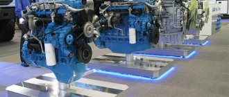
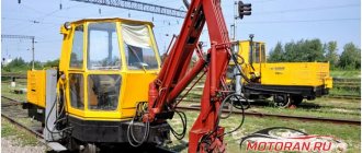
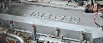
The famous Soviet bulldozers T-130 and T-170, as well as the Russian-made B-10 tracked tractor, would not have been half as popular and effective if it had not been for the D-160 engine installed in their design.
This diesel power plant has surpassed its age, and has been an integral component of some of the most powerful bulldozers for more than 30 years. Unpretentiousness, reliability and performance - all this is embodied by the motor thanks to its efficient design.
Basics
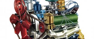
The basis of the engine is the cylinder block coupled with the crank mechanism. The cylinder block is a monolithic cast iron structure with insertable steel liners. Its partitions, together with the front and rear walls, serve as a support for the camshaft and crankshaft, as well as for the decompressor roller.
To monitor the condition of the main and connecting rod bearings, there are inspection hatches in the right wall. There are also hatches for mounting the pushers. The bottom of the D-160 engine is closed by a crankcase with two drain holes. A cylinder head is installed on top, common to two cylinders.
The five-bearing forged crankshaft is made of steel, has counterweights and channels in the crankpins, which ensures centrifugal oil cleaning. A flywheel with a gear ring is fixed to the shaft flange. The crown has straight teeth for motors with an electric starter, and oblique teeth for installations with a starting motor.
The piston is made of aluminum alloy, the combustion chamber is located at the bottom. The connecting rods are made from hot forged steel.
Engine structure.
D-180-device, operation and repair.
» Engine structure. The tractor is equipped with a four-cylinder, four-stroke, in-line diesel engine, liquid-cooled, supercharged by a turbocharger, with mixture formation and combustion of fuel in a chamber located in the bottom of the piston.
Cylinder block and crank mechanism
The main assembly unit that absorbs the loads during diesel operation is a cast iron cylinder block with insert liners. The vertical partitions of the block, together with the front and rear walls, serve as supports for the camshaft, crankshaft and decompressor roller. On the right side of the block there are hatches for inspection of the main and connecting rod bearings, and hatches for the pusher brackets. The lower part of the block is closed by a crankcase, which has two drain holes closed with plugs. Most of the diesel assembly units and units are attached to the block.
The block head is common to two cylinders. The gas joint between the head and the block is sealed with an asbestos-steel gasket or a gasket made of Fritex material.
The crankshaft is a forged steel five-bearing with counterweights and channels (cavities) in the connecting rod journals for centrifugal oil purification. Five main and four connecting rod bearings are steel-bronze. The flywheel is bolted to the crankshaft flange. The flywheel ring gear with straight teeth is for a diesel engine with ESSP, with oblique teeth for a diesel engine with a starting engine. To seal the output of the front and rear ends of the crankshaft, oil threads are cut on the toe and fifth main journal of the shaft, and rubber-frame cuffs are installed in the casings of the distribution gears and flywheel. On the toe of the crankshaft of a diesel engine with ESSP there is a ratchet for turning the crankshaft using the starting handle.
The piston is oval-barrel-shaped from an aluminum alloy with a combustion chamber in the bottom, with three compression rings and two oil scraper rings. Connecting rods are forged steel.
Balancing mechanism. To reduce vibrations that occur during operation, a balancing mechanism is installed on a diesel engine with a rated speed of 1250 rpm (Fig. 9.1). The mechanism is secured with four bolts on the lower plane of the block and covered with a crankcase. For correct installation of the balancing mechanism, there are marks on the gear tooth 2 and on the tide of the pan 13, as well as “C” marks on the teeth of the counterweights. Lubrication of the balancing mechanism bearings is centralized from the general diesel lubrication system. The teeth of the balancing mechanism wheels are lubricated by oil mist formed in the crankcase space during diesel operation. It is not recommended to disassemble the mechanism during operation.
| Rice. 9.1. Balancing mechanism: 1, 6 – bushing; 2, 5 – gear; 3 – thrust washer; 4, 12 – pin; 7 – nut; 8 – roller; 9 – leading counterweight; 10 – driven counterweight; 11 – body; 13 – pallet |
On diesel engines with a rated crankshaft speed of 1070 rpm, a balancing mechanism is not installed.
Gas distribution mechanism . The gas distribution mechanism consists of a cam camshaft, pushers with brackets, rods, rocker arms with rollers and struts, valves with springs. The valves are suspended, one inlet and one exhaust for each cylinder.
The camshaft ensures timely opening and closing of valves in accordance with valve timing.
At the front end of the camshaft there is a double gear, the large crown of which meshes with the crankshaft gear, and the small crown meshes with the fuel pump regulator drive gear. For proper installation, both rings and mating gears have marks on the teeth. The thrust disc limits the axial movement of the shaft in the range from 0.10 to 0.33 mm.
The decompression mechanism is designed to force open the intake valves to facilitate cranking of the diesel engine before starting or during adjustments, as well as emergency stopping of the diesel engine in emergency situations. The opening of the valves is ensured by the action of the decompressor rods on them when turning its roller.
The fuel supply system (Fig. 9.2) consists of a tank, injectors, a high-pressure fuel pump with a speed controller and a flow lubrication system from the general diesel lubrication system, a fuel priming pump, coarse and fine fuel filters.
Rice. 9.2. Diesel fuel supply system:
1 – nozzles; 2 – high pressure tubes; 3 – fuel line for removing fuel from the fine filter; 4 – fine fuel filters; 5 – pipe for bypassing and draining fuel leaks; 6 – fuel supply tube to the ECU; 7 – solenoid valve; 8 – glow plug EFU; 9 – regulator; 10 – fuel line for supplying fuel to the fine filter; 11 – route for draining oil from the fuel pump into the diesel crankcase; 12 – fuel priming pump; 13 – fuel pump; 14 – fuel coarse filter; 15 – fuel supply tube to the coarse filter; 16 – fuel tank; 17 – fuel tap; 18 – drain valve; a – fuel that has been cleaned in a coarse filter; b – purified fuel; c – fuel drained from injectors and fine filter
The fuel tank is equipped with a filler neck with a filter, a cap with a drainage hole, a fuel gauge, and a fuel level sensor. The drain and fuel valves are located at the bottom of the tank.
The drain valve is designed to drain sludge and fuel from the fuel tank. The tap is located on the bottom of the tank on the left side along the tractor. To access the tap, you must remove the shield.
The fuel pass-through valve is located on the right side on the bottom of the fuel tank and serves to disconnect the fuel tank from the power system in necessary cases.
To drain the fuel from the tank, turn the drain valve handle counterclockwise until it stops.
To supply fuel from the tank, open the fuel tap by turning the valve handle flag horizontally to the right (along the tractor's direction).
To stop the supply of fuel in the tank to the diesel fuel system, close the fuel valve by turning the valve handle flag horizontally to the left (along the tractor's direction).
High-pressure fuel pump (Fig. 9.3), sectional four-plunger, with fuel bypass, with a plate-type fuel supply corrector.
Rice. 9.3. High pressure fuel pump:
1 – bearing housing; 2 – bearing cover; 3 – bolt; 4 – locking plate; 5 – thrust washer; 6 – corrector spring; 7 – coupling locknut; 8 – regulating coupling; 9 – pusher locknut; 10 – pusher shank; 11 – corrector cover; 12 – plunger; 13 – sleeve; 14 – discharge valve; 15 – discharge valve spring; 16 – shield; 17 – rack; 18 – bolt; 19 – clamping square; 20 – fuel bypass fitting; 21 – guide plate; 22 – rack rod; 23 – rack thrust ring; 24 – front camshaft bushing; 25 – cam shaft; 26 – pump block; 27 – fuel priming pump; 28 – pusher roller; 29 – pusher roller axis; 30 – pusher; 31 – pusher spring; 32 – connecting tube; 33, 38 – sealing ring; 34 – discharge valve seat; 35 – purge valve needle; 36 – section body; 37 – fitting; 39 – locking screw; 40 – gear sector; 41 – slatted leash; 42 – side hatch cover; 43 – drain plug
In the upper part of the pump housing there are four interchangeable sections with plungers with a diameter of 12 mm, discharge valves and a fuel bypass fitting.
Inside the housing are installed a cam shaft, four pushers with springs, a rack and a rack rod. The fuel supply corrector is located on the rear surface of the housing.
In order to limit the diesel power during the running-in period of the tractor, a screw is installed in the fuel pump corrector cover.
A piston-type fuel priming pump is designed to supply fuel from the tank to the fuel pump and manually pump fuel while removing air from the fuel system. On diesel engines with an electric flare device installed, the fuel priming pump is designed to create pressure in the fuel line connected to the spark plug before starting the diesel engine.
The speed controller (Fig. 9.4) is an all-mode centrifugal one. It consists of a housing, a drive shaft, a vertical shaft with weights and a coupling, a lever system, rods, springs, bolts for regulating the minimum and maximum rotation speeds, an outer lever, etc.
Rice. 9.4. Regulator:
1 – bevel gears; 2 – oil drain plug; 3 – drive shaft; 4 – three-arm lever; 5 – traction; 6 – maximum feed bolt; 7 – spring; 8 – cover; 9 – lever; 10 – regulator roller; 11 – cover; 12 – bearing; 13 – coupling; 14 – lever; 15 – cargo; 16 – gasket; 17 – thrust plate; 18 – washer; 19 – bushing; 20 – bearing housing; 21 – lower regulator roller; 22 – emphasis; 23 – lever; 24 – spring; 25 – minimum feed bolt; 26 – regulating coupling; 27 – roller; 28 – roller; 29 – emphasis; 30 – guide pins; 31 – body
The regulator, acting on the pump rack through a system of levers and rods, changes the fuel supply depending on the load and maintains a given rotation speed.
To drain oil from the regulator body, a plug is installed on the bottom plane of the body.
Fuel filters. To filter fuel, three filters are installed: a filter in the filler neck of the fuel tank, a coarse fuel filter in front of the booster pump, and a fine filter in front of the fuel pump. Coarse filter - with a mesh filter element and a tap for draining sediment, fine filter - with two replaceable paper filter elements.
Closed-type injectors with five spray holes are mounted in the cylinder head with cap levers. A slot filter element is installed in the nozzle fitting.
The electric torch device consists of a torch pin spark plug and an electromagnetic valve mounted on the pipe between the turbocharger and the diesel intake manifold, as well as a resistor with an electrothermal relay 1212.3741, a blocking relay 901.3747-010 and a switch 11.3704.01.
Fuel for the EPU from the fine filter flows through the fuel line to the solenoid valve and, after it opens, to the spark plug.
The principle of operation of the EFU is based on the evaporation of fuel in a spark plug, mixing fuel vapors with air into a combustible mixture and igniting it from an incandescent coil located in the spark plug.
The flame torch heats the air entering the diesel cylinders and thereby facilitates the start of the diesel engine.
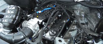
The air supply system consists of an air cleaner, turbocharger, intake and exhaust manifolds, muffler with exhaust pipe.
The diesel air cleaner (Fig. 7.3) is two-stage: the first stage is a multicyclone cleaner, consisting of 12 direct-flow cyclones and a pipe for automatic ejection dust suction. The second stage is the main paper filter elements (EF) and safety filter cartridges (FP), which are a metal frame with a fabric cover made of needle-punched fabric.
Turbocharger 8.5C (Fig. 9.5) or K27 - a diesel supercharging unit - is a single-stage centrifugal compressor driven by a radial centripetal turbine operating in the flow of diesel exhaust gases. The gas temperature at the turbine inlet without time limitation is not more than 650 °C. The turbocharger is installed on the exhaust manifold flange. To lubricate the rotor shaft, oil is supplied under pressure from the general diesel lubrication system. To dose the oil supply, an adapter with a calibrated hole with a diameter of 2.5 mm is installed at the inlet of the turbocharger. The adapter contains an emergency oil pressure sensor MM 111 V.
Rice. 9.5. Turbocharger 8.5C:
1 – turbine housing; 2 – bearing; 3 – remote bushing; 4 – bearing housing; 5 – shield; 6 – disk;
7 – compressor housing; 8 – compressor wheel; 9 – nut; 10,11,12,13,18 – ring; 14 – thrust bearing;
15 – flange (installation location of the adapter with the MM111V sensor); 16 – gasket; 17 – screen; 19 – shaft; 20 – bushing; 21 – screw; 22 – hairpin
During operation, the turbocharger does not require regulation, but it is necessary to systematically monitor its operation. At the beginning of engine operation, a specific, gradually increasing high-pitched sound appears, characteristic only of a supercharged diesel engine, which confirms the normal operation of the turbocharger.
The turbine wheel assembly with the compressor wheel is subjected to high-precision dynamic balancing using special equipment. Therefore, the turbocharger can only be disassembled in specialized workshops.
lubrication system (Fig. 9.6, 9.7) is combined: under pressure from a gear oil pump and by splashing.
Oil pressure in the main oil line:
– from 0.3 to 0.5 MPa (from 3 to 5 kgf/cm²) at rated speed;
– not less than 0.04 MPa (0.4 kgf/cm²) at a minimum stable idle speed.
ATTENTION! When starting the diesel engine, do not turn on the fuel supply until the warning lamp for the emergency pressure indicator in the lubrication system goes out.
Rice. 9.6. Diesel lubrication system diagram (longitudinal section):
1 – entrance to the main oil line; 2 – oil pressure indicator; 3 – drain valve; 4 – filter element; 5 – bypass valve; 6 – filter oil channel; 7 – oil pressure indicator sensor (at the entrance to the main oil line); 8 – window for draining oil into the crankcase; 9 – double acting valve*; 10 – oil drainage channel to the radiator; 11 – oil distribution plate; 12 – channels for supplying oil to the main bearings; 13 – main oil line; 14 – oil supply pipe to the turbocharger; 15 – oil supply tube to the rocker shaft; 16 – oil drain pipe from the turbocharger; 17 – channel for supplying oil to the upper head of the connecting rod; 18 – oil supply channel to the front camshaft bearing; 19 – channel for supplying oil to large intermediate gears; 20 – channels for supplying oil to the connecting rod bearings; 21 – plug; 22 – oil radiator; 23 – plug; 24 – front oil receiver; 25 – oil pump; 26 – cavity for centrifugal oil purification in the connecting rod journal; 27 – oil drain from the radiator; 28 – oil pump; 29 – magnetic plug; 30 – central oil receiver; 31 – crankcase reservoir; 32 – safety valve; 33 – holes for draining from the pumping section of the pump; 34 – rear oil receiver; a – oil that has not undergone purification; b – refined oil
The oil pump is three-section, with two injection sections and one pump-out section.
When the diesel engine is running, the injection sections supply oil from the central and front oil receivers of the crankcase to the oil distribution plate, and the pumping section pumps oil from the rear of the crankcase and from the fifth main bearing into the middle part of the crankcase to the central oil receiver. The safety valve limits the pressure developed by the pump.
From the oil distribution plate, oil flows to the oil filter and oil cooler. The oil cooled in the oil cooler is drained into the crankcase.
Full-flow oil purification filter with replaceable paper filter elements (BFE) (Fig. 7.5). To determine the need to replace the BFE, a clogging alarm sensor is installed on the filter housing.
ATTENTION! It is acceptable for the oil filter clogged warning lamp on the instrument panel to light up at the time of start-up and during the oil warm-up period. The lamp should not light on a warm diesel engine.
The oil filter drain valve regulates the pressure in the main oil line, and the bypass valve, in the event of a clogged BFE, transfers raw oil from the filter housing to the main oil line. The drain valve has an adjustment unit that allows you to smoothly regulate the oil pressure in the oil line.
The purified oil flows through the main oil line and channels in the block to the main and connecting rod bearings of the crankshaft, the front camshaft bearing, the bearings of the intermediate gears, the vertical shaft of the regulator and the balancing mechanism, and through the tubes to the rocker shafts and the turbocharger. The amount of oil supplied to the turbocharger is dosed through a 2.5 mm diameter hole in the adapter at its inlet.
The oil entering the regulator housing flows into the fuel pump housing, provides lubrication to the rubbing parts of the pump and is drained through a pipeline into the diesel crankcase.
From the crankpins of the crankshaft, oil flows through channels in the connecting rods to the bushings of the upper heads of the connecting rods and piston pins, and through the channels in the upper heads is injected onto the piston heads, cooling them. The remaining assembly units and parts are lubricated by splashing.
The oil radiator is tubular-plate.
An electrically driven oil pump (OPL) (Fig. 9.8) is used to create oil pressure in the diesel lubrication system before starting the diesel engine. The MZN is installed on the crankcase hatch on the side where the oil gauge is located.
Rice. 9.8. Installation of the oil injection pump (OMP):
1 – oil distribution plate; 2 – oil supply channel to the main oil line; 3 – valve; 4 – channel for supplying purified oil from the filter; 5 – fitting; 6, 8 – rings; 7 – valve seat; 9 – ball; 10 – spring; 11 – oil supply pipelines from the oil pump to the oil distribution plate; 12 – oil pump (MZN); 13 – oil intake tube from the crankcase; 14 – hatch cover; 15 – crankcase; a – during operation of the MZN; b – during diesel operation
The diesel cooling system (Fig. 9.9) is liquid, closed, with forced circulation of coolant from a centrifugal pump. The coolant temperature in the system is controlled automatically by two double-acting thermostats. When the coolant heats up to 70 °C, one of them closes the small circuit, directing the entire flow of liquid to the radiator, which increases the efficiency of the cooling system.
Centrifugal type cooling pump with mechanical seal.
The radiator of the cooling system is tubular with cooling plates and a steam-air valve. The coolant temperature at the diesel engine outlet is from 65 to 85 °C.
The fan is axial, six-bladed, belt driven from the crankshaft pulley. The belts are tensioned by a tension mechanism.
Rice. 9.9. Cooling system diagram:
1 – radiator drain valve; 2 – lower collector; 3 – radiator core; 4 – upper collector; 5 – radiator filler plug; 6 – steam-air valve; 7 – steam-air tube; 8 – connecting pipe; 9 – connecting sleeve; 10 – fan shield; 11 – fan; 12 – cooling system pump; 13 – drainage hole; 14 – control and drain hole; 15 – bypass tube; 16 – double-acting thermostats; 17 – cover; 18 – cavity of the cylinder head cooling jacket; 19 – deflector; 20 – drainage pipe; 21 – coolant temperature sensor; 22 – coolant temperature indicator receiver; 23 – cavity of the diesel cylinder coolant jacket; 24 – coolant drain valve; 25 – starting motor pipe; 26 – cavity of the jacket of the starting engine cylinder head; 27 – starting motor; 28 – pipe for supplying coolant to the diesel cylinder block; 29 – cooling system pump pipe; 30 – cover; a – direction of the coolant during diesel operation; b – draining the coolant from the system; I – tractor diesel cooling system with ESSP
Design features
To dampen vibrations produced by the D-160 engine when operating at a rated speed of 1250 rpm, a balancing mechanism is installed. It is located on the lower plane of the block and is hidden by the crankcase. The lubrication of the bearings of this mechanism is centralized, but the teeth of its wheels are lubricated by oil mist that forms in the internal chamber of the motor.
Another design feature is the presence of a decompression mechanism. It opens the intake valves of the cylinder head during engine starting, adjustments or during an emergency stop. Thanks to its operation, the crankshaft does not encounter resistance and rotates freely. The valves are opened by decompressor rods, which act on them by turning the mechanism shaft.
Cooling system
The D-160 engine is equipped with a closed liquid cooling system with forced circulation of coolant - water or antifreeze. It is provided by a centrifugal pump with a mechanical seal. The radiator has a tubular design with a steam-air valve and cooling plates.
Two thermostatic valves are responsible for regulating the engine temperature. When the coolant heats up to 70°C, one of them is activated, shuts off the small circuit and forces the liquid to circulate through the radiator. This ensures more efficient and faster cooling of the power plant.
Fuel system
The fuel system consists of a tank, injection pump, filter and injector systems. Fuel, before entering the D-160 diesel engine, passes through a system of 3 filters:
- the first is installed in the filler neck of the tank for preliminary cleaning of fuel;
- the second, intended for rough cleaning, is mounted in front of the booster pump;
- the third, necessary for fine cleaning of the fuel, is installed directly in front of the fuel injection pump.
An additional booster pump acts as an intermediate link between the tank and the injection pump. It also serves to remove air from the lines and create pressure in the system in engines with electric torch devices.
Repair instructions for the D-160 engine
From the moment it went into mass production, each copy of the D-160 was accompanied by a repair manual, compiled in such a way that the driver could fix most of the faults himself. Serious work, such as adjusting valves, was carried out in auto repair shops, but minor breakdowns were often repaired almost without interrupting the work process. Today, the engine repair book is available in electronic format. It contains a detailed image and description of parts and assemblies, a list of possible faults and methods for eliminating them, as well as photos of the engine from different angles.
Be sure to read: Transport tax is not canceled
Fuel system features
A screw is installed in the cover of the high-pressure fuel pump corrector, which limits the power of the power plant during equipment break-in. The injectors are secured in the head of each cylinder with cap levers.
The electric torch mechanism installed in the D-160 engine deserves attention. The EFU device is a pin spark plug and an electromagnetic valve attached to it. The fuel evaporates directly in the spark plug, after which fuel vapors mix with air and detonation occurs from the glowing spark plug coil. The resulting flame torch simultaneously heats the air entering the cylinders, thereby facilitating engine starting.
Air supply and lubrication system
Air is supplied using an air purifier consisting of 12 direct-flow cyclones and an 8.5 C turbocharger. The latter operates using exhaust gases. They spin a radial centripetal turbine. During operation, no element of the system requires regulation, but the operation of the compressor must be monitored. It is not recommended to disassemble the air supply mechanism yourself.
The D-160 engine capacity is about 14 liters, and its operation directly depends on the lubrication system. Therefore, in the design of the presented power plant it is combined - lubrication is carried out by a gear pump and a sprinkler. Before engine oil is supplied to the system, it passes through a filter with replaceable paper elements. To make it easy to monitor the filter life, there is an indicator of clogging of replaceable elements on its side.
Before starting the engine, the oil injection pump creates excess pressure in the system, thereby facilitating the operation of the power plant.
Engine D-160 D-180 tractor T-170 T-130
The warehouse always has both new and D160, D180 engines with cap. repair Repaired engines for bulldozers T-170, T-130, B-10 have a 9-month warranty. We also have a large selection of spare parts for the 65-14-029sp D180, D160 and PD-23 engines in stock.
To order spare parts for the T-170 B10M bulldozer, call 83 or send a request by email [email protected]
All engines and spare parts are in stock.
Remember, if they sell you a new D160 engine, they are deceiving you! The T-130 (D-160) engine has not been produced for more than 15 years and is only available after a major overhaul.
The tractor engine T-170 and T-130 are mutually interchangeable.
Engine T-130 D-160
with overhaul
price 345,000 rubles
Engine T-170 D-180
65-14-029 sp with overhaul
price 530,000 rubles
All engines in stock
.
All T-170 T130 engines have passports
.
Engine weight D160 D180 -2100 kg
Engine (overhaul) D-160 with electric starter price
Engine (overhaul) D-180 with electric starter price
We provide a 6 month or 500 hour warranty on all engines.
When overhauling T-170 T-130 D-160, D-180 engines, we change:
— piston group (145 mm, 150 mm) — main and connecting rod bearings — intake and exhaust valves — turbochargers TKR-11 N3, TKR-8.5 S — connecting rod bushings — gaskets and rubber goods — diesel regulator — bearings — sensors — oil pump — replacement of fuel equipment (nozzles and plunger pairs) The PD-23 starting engine is replaced with a new one or undergoes a complete overhaul.
Each diesel engine of the T 170 T 130 tractor is tested. We send engines by any transport company or passing transport.
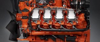
Offered engines D180 D160 is an in-line four-stroke diesel 4-cylinder engine, supercharged by a turbocharger, liquid cooling, mixture formation and fuel combustion in the piston bottom chamber. The design of diesel engine d 160 and diesel engine d 180 are generally similar. The D-180 is equipped with a piston group with a diameter of 150 mm instead of 145 mm, attachments: a TKR-8.5 turbocharger instead of a TKR 11N3, fuel injection pump and diesel regulator, and manifold housings. This increases power, but at the same time, an improved, but more expensive linkage makes the D 180 engine more expensive than the D 160 engine.
From us you can purchase a full range of spare parts for repairing diesel engines D 180 D 160
.
Always in stock is a piston group for tractors B-170 B-130 with a diameter of 150 and 145 for engines D-180, D-160.
All spare parts and repair kits for the D 160 D 180 engine are in stock.
| Technical characteristics of ChTZ engine d-160 on t130 | ||
| Tact | four-stroke | |
| Air supply type | turbocharging with two-stage air purification | |
| Cooling type | liquid | |
| Number and arrangement of cylinders | 4P | |
| Cylinder diameter, mm: | ||
| D-160, D-160B-1 | 145 | |
| D-160.01, D-160.01B-1,160.03 | 150 | |
| Piston stroke, mm | 205 | |
| Cylinder displacement, l: | ||
| D-160, D-160B-1 | 13,53 | |
| D-160.01, D-160.01B-1, D-160.03 | 14,48 | |
| Cylinder operating order*1 | 1-3-4-2 | |
| Combustion chamber type | semi-divided | |
| Rated power*2, kW (hp): | ||
| D-160, D-160.01 | 128.7+3,7 (175+5) | |
| D-160B-1, D-160.01B-1 | 105.2+3 (143+4) | |
| D-160.03 | 136+3,7 (185+5) | |
| Operating power*3, kW (hp): | ||
| D-160, D-160.01 | 125+3,7 (170+5) | |
| D-160B-1, D-160.01B-1 | 103+3 (140+4) | |
| D-160.03 | 132+3,7 (180+5) | |
| D-160.101-4 | 118+3,7 (160+5) | |
| Nominal rotation speed, rpm: | ||
| D-160, D-160.01, D-160.03 | 1250±30 | |
| D-160B-1, D-160.01B-1 | 1070±30 | |
| at maximum torque, not less | 800 | |
| idle speed maximum: | ||
| D-160, D-160.01, D-160.03 | 1320±30 | |
| D-160B-1, D-160.01B-1 | 1140±30 | |
| minimum stable, no more | 550 | |
| Direction of rotation of the crankshaft (fan side) | right | |
| Maximum torque, N/m (kgf/m), not less*4: | ||
| D-160, D-160.01 | 1098 (112) | |
| D-160B-1, D-160.01 B-1 | 1056 (108) | |
| D-160.03 | 1162 (118) | |
| Installation angle of fuel injection advance to TDC, degree | 24±2 | |
| Specific fuel consumption at operating power, g/kW x h (g/l. s x h): | ||
| D-160. D-160.03 | 231+7 (170+5) | |
| D-160B-1 | 229+7 (168+5) | |
| D-160.01 | 224+7 (165+5) | |
| D-160.01 B 1 | 222+7 (163+5) | |
| Valve timing, degrees: | D-160, D-160.01, D-160.03, D-160B-1, D-160.01B-1 | |
| start of intake to TDC | 8±5 14±5 | |
| intake end after BDC | 37±5 40±5 | |
| start of release before BDC | 47±5 60±5 | |
| end of release after TDC | 10±5 10±5 | |
| Oil pump performance at back pressure 0.7-0.8 MPa (7-8 kgf/cm2), pump shaft rotation speed (1700±50) rpm and oil temperature 75-85°C, l/min, not less | 90 | |
| Oil pressure in the main oil line at an oil temperature in front of the oil cooler of 70-85°C, MPa (kgf/cm2): | ||
| at rated speed | 0,2-0,5 (2-5) | |
| at minimum stable idle speed, not less | 0,09 (0,9) | |
| Oil consumption for waste: | ||
| — relative, percentage of fuel consumption | 0,2-0,5 | |
| — specific, g/kW x h (g/l.s x h), no more | 1,1 (0,8) | |
| — relative total oil consumption, percentage of fuel consumption, no more | 1,2 | |
| 1,2 | ||
| Coolant temperature at the diesel engine outlet at rated (operating) power mode, °C | 65-85 | |
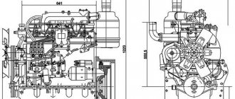
| Dimensions of diesel engine included in delivery, mm: | ||
| - with starting motor: | ||
| length (with pallet) | 1795±50 (1870) | |
| width (with pallet) | 1187±50 (1200) | |
| height (without exhaust pipe) (with tray) | 1741±50 (1960) | |
| - with electric start: | ||
| length | 1732±50 | |
| width | 1187±50 | |
| height (without exhaust pipe) | 1728±50 | |
| Diesel weight, included in delivery, kg: | ||
| - with starting motor: | ||
| D-160, D-160.01, D-160.03 | 2126±60 | |
| D-160B-1, D-160.01B-1 | 2126±60 | |
| - with electric start: | ||
| D-160, D-160.01, D-160.03 | 1949±60 | |
| D-160B-1, D-160.01B-1 | 1912±60 | |
| Starter type | starting motor or electric starter | |
| Power take-off from the front end of the crankshaft as a percentage of rated power, no more | 85 | |
| including: | ||
| — through the crankshaft pulley, no more | 50 | |
| — through the hydraulic pump drive gear, no more | 60 | |
| Limit tilt angles of diesel engines, degrees: | ||
| longitudinal | 30 | |
| transverse | 20 | |
| Volumes, l: | gas station | drainable |
| cooling systems with a radiator with low-freezing liquid (water) | 60±5 (65±5) | |
| diesel crankcase | 32±2 | 20.5 no less |
| starting motor housing | 1,9±0,2 | 1.4 no less |
| starting motor gear housing | 0,6±0,2 | 0.48 no less |
| fuel pump housing | 0,6±0,1 | 0.55 no less |
| oil bath of the starting engine air cleaner | 0,07±0,01 | |
| Turbocharger | ||
| Brand | TKR 11N-3 | |
| Turbine type | radial-axial | |
| Compressor type | centrifugal | |
| The degree of compressor pressure increase at the nominal diesel operating mode, not less: D-160, D-160.01, D-160B-1, D-160.01B-1, D-160.03 | 1,45 | |
| Turbocharger mass, kg, no more | 20 | |
| Starting motor | ||
| Brand | P-23U | |
| Type | carburetor gasoline, four-stroke | |
| Number of cylinders | 2 | |
| Cylinder diameter, mm | 92 | |
| Piston stroke, mm | 102 | |
| Direction of rotation of the crankshaft (from the timing gear housing side) | left | |
| Rated power under standard atmospheric conditions not less than, kW (hp) | 13,25 (18) | |
| Crankshaft rotation speed at rated power, rpm | 2400±100 | |
| Idle speed, rpm: | ||
| maximum | 2800±50 | |
| minimum, no more | 600 | |
| Cylinder operating order*5 | 1-2-0-0 | |
| Specific fuel consumption at rated power, g/kW x h (g/l. x h.), no more | 450 (330) | |
| Fuel | gasoline A-72 or A-76 according to GOST 2084-77 | |
| Carburetor | K 125L | |
| Air purifier | oil-inertial | |
| Valve timing, degrees: | ||
| start of intake | 8±2 before TDC | |
| intake end | 34±2 after LBW | |
| start of release | 44±2 before BDC | |
| end of release | 8±2 after TDC | |
| Speed controller | centrifugal | |
| Ignition | from magneto | |
| Ignition timing, degrees based on the crankshaft rotation angle | 25 | |
| Cooling type | liquid, common with the main engine | |
| Lubricant type | splashing | |
| Gearbox | two-stage with spur gears | |
| Switching mechanism | Bendix type with manual activation and automatic shutdown | |
| Clutch type | non-permanently closed, lever, single-disc, dry | |
| Weight, kg | 220±10 | |
| Starting the engine | electric starter ST-230E | |
| Electrical equipment | ||
| Generator 70.3701: | ||
| Power, W | 1000 | |
| Rated voltage, V | 28 | |
| Starter 251.3708*6: | ||
| Operating voltage, V | 24 | |
| Power, W | 8200 | |
| Starter ST-230E: | ||
| Operating voltage, V | 12 | |
| Power, W | 1500 | |
| Magneto | M-149-A | |
| Spark plug | M-8T1 | |
| Technical characteristics of the ChTZ engine d-180 | |
| engine's type | four-stroke turbocharged, 4-cylinder in-line |
| Cylinder diameter, mm | 150 |
| Piston stroke, mm | 205 |
| Working volume, l | 14,48 |
| Torque reserve,% | 25 |
| Specific fuel consumption, g/kW*h (g/hp*h) | 218 (160) |
| Operating power, kW (hp) | 132 (180) |
| Starting a diesel engine | from an electric starter or starting motor |
| Weight with electric start, kg | 1890 |
| Weight with starting motor, kg | 2095 |
| Dimensions, mm: | |
| — length (with pallet) | 1730 (1870) |
| — width (with pallet) | 1190 (1200) |
| — height (with tray) without exhaust pipe | 1730 (1960) |
| Two-stage air cleaner: | |
| - first stage | multicyclone with automatic dust removal; |
| - second stage | paper filter elements. |
| Cooling system | liquid |
| Lubrication system | combined with a full-flow filter with replaceable paper elements |
Engine Specifications
Thanks to the coordinated operation of the components and mechanisms presented above, the D-160 engine operates almost without failure and with minimal fuel consumption (for this class of machines). The technical characteristics of the power plant, which are at such a high level, also largely depend on the structural elements of the motor.
There is no need to say that the manufacturer supplies the market with several modifications of this engine. Each unit differs only in its technical characteristics.
The D-160 engine is the brainchild of the Chelyabinsk Tractor Plant. Despite its venerable age, it can give odds to many modern power units. However, like any other motor, it periodically needs repairs.
Due to high maintainability and availability of spare parts, there are no maintenance problems. The only thing that is of concern is the major renovation.
Second life of the engine
If during operation there is a decrease in cylinder compression, uneven idling, an increase in fuel consumption, as well as the appearance of strong vibration and extraneous noise, then know that spare parts will no longer save your D-160 engine. A major overhaul is needed here.
Overhaul is an inevitable stage in the life of every power plant. It is important that it be done thoroughly. The price of a new power plant is at the level of 240 thousand rubles, which is why overhaul is a more profitable alternative. During repair operations it is desirable to replace:
- piston group;
- main and connecting rod bearings;
- intake and exhaust valves of the cylinder head;
- connecting rod bushings;
- oil pump;
- gaskets and rubber components.
During restoration work, it is also necessary to check the operation of the fuel system. The most vulnerable elements are the injectors and plunger pairs of the high-pressure fuel pump. In addition, the starting motor must also be checked. In some cases it cannot be restored. Then there is only one way out - a complete replacement of the mechanism.
The presented characteristics of the D-160 engine are not able to fully describe its functional and technical features. Thanks to its operation, in combination with a powerful transmission unit, the tractors operating it belong to traction classes 6 and 10 and are highly efficient and economical representatives of tracked vehicles.
Description of the D-160 diesel engine
D-160 is the result of consistent modernization of ChMP production. By this time, tractor engines had already acquired gas turbine supercharging, but this was not enough to provide the required power. By increasing the size of the cylinder-piston group and optimizing the fuel supply, an impressive power of 160-170 hp for that time was achieved. With. The new product successfully passed tests and was put into mass production. Since 1981, the D-160 began to be installed on tractors and excavators produced by ChTZ. The fact that the equipment and engines had a common manufacturer reduced the cost of production and ensured full compatibility of all units.
The engine was manufactured at the Chelyabinsk Tractor Plant
Engine design
The main part that takes on the load when the engine is running is the cylinder block. The D-160 has cast iron. The tightness of the joint between the block and the head is ensured by a copper-asbestos gasket. There are five support points for the crankshaft (outer walls and internal partitions). The flywheel is cast iron, attached to the crankshaft flange (bolt connection).
The main and connecting rod bearings are interchangeable and made of an alloy of steel and aluminum. There are three compression rings, two oil scraper rings. The upper rings are chrome plated. The radial expander is installed under the upper oil scraper ring. The combustion chamber is located at the bottom of the piston.
Combined lubrication system. Some parts are lubricated under pressure from a gear pump. In the same way, lubricants are supplied to the crankshaft and camshaft bearings, idler gears, timing mechanism, vertical governor shaft, turbocharger and counterbalance mechanism, as well as to the piston crown. Other parts are splash lubricated.
Be sure to read: Technical characteristics of the D-242 engine
The oil pump consists of three sections : two pressure sections move oil from the crankcase to the main line, and the pump-out section returns it to the central oil sump. Overheating of the lubricant is prevented by a tubular radiator. The lubricant is cleaned by a centrifuge and a filter.
The cooling system is liquid, closed. Coolant circulation is ensured by force. The temperature is regulated by thermostats; in winter, it is recommended to additionally use an insulating cover. The radiator design with a steam-air valve increases the boiling point and protects the tubes from destruction when the pressure deviates from the operating level.
The power supply system includes a fuel tank, a high-pressure pump D-160 injection pump, a fuel pump, filters, low- and high-pressure fuel lines and injectors.