Category: KAMAZ
- General information about the scheme
- External lighting
- Starting the power plant
- Power supply for electrical equipment
- Light signaling
- Heater and wiper
- Warning lamps and instruments
- Interior lighting
Trucks from the Kama Automobile Plant are used to transport various goods. The KamAZ 5320 wiring diagram is necessary for repairing and servicing the vehicle. The electrical system of a car refers to a set of devices connected by wires according to a specific circuit.
General information about the scheme
The electrical circuit of KamAZ 5320 is made according to the single-wire principle. The negative contact is the car body. The negative terminal of the battery and the negative terminals of the devices are attached to it. The plus of the battery is connected to consumers using copper wires.
IMPORTANT: To avoid short circuits in the vehicle’s on-board network, the wires are equipped with insulation that is resistant to moisture and temperature changes.
Electrical equipment includes several systems simultaneously:
- External lighting;
- Starting the power unit;
- Power supply for electrical equipment;
- Light signaling;
- Autonomous heater;
- Windshield cleaning;
- Instruments and control lamps;
- Salon lighting.
Where can I buy
Spare parts and other products for the car are easily available for purchase at auto stores in your city. But there is another option that has recently received significant improvements. You no longer need to wait a long time for a parcel from China: the AliExpress online store now offers the opportunity to ship from transshipment warehouses located in various countries. For example, when ordering, you can specify the “Delivery from the Russian Federation” option.
Follow the links and choose:
External lighting
External lighting of the KamAZ 5320 is necessary for using the machine at night. This includes:
- Low and high beam headlights;
- License plate lighting;
- Engine compartment lamp;
- Fog lights;
- A headlight that illuminates the space under the body.
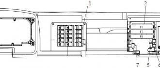
Consumers are included in the electrical circuit through a fuse block. This protects the wiring from fire if a short circuit occurs. To control the system, switches located in the driver's cab are used.
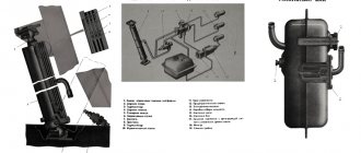
Electrical diagram of the heating system, sound alarm and windshield wiper systems
This system is responsible for the operation of the heating system of the car, or in common parlance, the stove. In addition, it is responsible for powering the wipers and sound signal. This system has the following electrical diagram:
- heater electric motor;
- heater motor switch;
- wiper;
- heater motor relay;
- fuse 13.3722 (7.5 A);
- fuse PR 310 (10 A);
- windshield washer switch;
- windshield washer,
- wiper switch;
- combination light switch;
- sound signal (buzzer);
- tonal signals;
- horn relay;
I. to terminal AM of the instrument switch and starter;
II. to the short circuit terminal of the instrument switch and starter;
III. to the brake signal relay;
IV. to the signaling unit.
Starting the power plant
The power unit is started by an electric starter with a supply voltage of 24 Volts. The starter is powered by two 12 V batteries. The batteries are connected in series.
The positive wire from the batteries is attached to the starter. The electric starter is controlled via a relay using an instrument switch. You can also read about the KamAZ 6520 PGU.
Power supply for electrical equipment
When the engine is turned off, consumers are powered by batteries. They are included in the circuit using a ground switch. The mass is turned off remotely. After starting the power unit, the equipment is powered and the batteries are charged by a DC generator.
The generator is connected in parallel to the batteries and has an excitation winding. To stabilize the voltage at different speeds of the power unit, the system includes a relay regulator.
KamAZ turn relay operating principle.
The operating principle of the KamAZ RS 950 turn relay is the same as other electronic turn relays. An electromagnetic relay is used as a power supply breaker for the signal paws. The relay is controlled by supplying power to its coil from an electronic multivibrator, the circuit of which is assembled on an integrated circuit or from individual elements. From the contacts of the electromagnetic relay, power is supplied to the turn signal or hazard warning switches. After which the plus passes through one of the reed switch coils or electromagnetic relays of the warning lamps to the warning lamps.
Depending on the manufacturer, the relay may be equipped with a low-current relay or a reed switch to turn on the warning lamp. There are usually two of them installed in the PC-950 to turn on the warning lamps of the tractor trailer. Each of the reed switches or relays has two coils, each of which is connected to the circuit of signal lamps on the right or left side of the trailer or tractor. Reed switches or relays, when current passes through their coils, close their contacts and supply power to the warning lamps of the tractor and trailer.
Light signaling
The system is necessary for safe use of the vehicle on public roads. Using the system, the driver indicates a maneuver for other road users.
Light signaling consists of:
- Rear and front lights;
- Road train lamps;
- Turn signal switch;
- Hazard switch;
- Relays and fuses;
- Brake light switch.
REFERENCE: The light alarm is equipped with a socket for connecting trailer wiring.
Electrical functional diagrams KamAZ-5320, -55102
ELECTRICAL FUNCTIONAL DIAGRAMS
All diagrams have a single list of elements; the location zones of elements in semi-assembled diagrams may differ slightly (Fig. 328-337).
| Zone | Pos. convoy | Name | Col. |
| 5A | B1 | Auxiliary brake sensor MM125D-3810600 TU37.003.546-76 | 1 |
| 5A | B2 | Fuel level sensor SYAMI 407 611-114-01 (or SYAMI 407 611-114-02) TU4573-002-12258598-93 | 1 |
| 5A | B3 | Speedometer sensor 2001.3843 TU37.003.1270-75 | 1 |
| 5A,5B,5B,1A | B4, B5, B6, B13 | Pressure drop sensor in brake circuits 1, 2, 3, 4 MM124D-3810600 TU37.003.546-76 | 4 |
| 2A | B7 | Oil filter clogged warning lamp sensor | 1 |
| 1A | B8 | Oil pressure sensor MM370 TU37.003.387-78 | 1 |
| 1A | B9 | Emergency oil pressure sensor MM111D-3810600 TU37.003.546-76 | 1 |
| 1A | B10 | Temperature indicator sensor TM-100A TU37.003.568-77 | 1 |
| 1A | B11 | Temperature alarm sensor TM111 TU37.003.569-90 | 1 |
| 1A | B12 | Parking brake warning lamp sensor MM124D-3810600 TU37.003.546-76 | 1 |
| 5B,2B | E1, E25 | Fog lamp FG152A TU37.003.751-80 | 2 |
| 5B,2B | E2, E24 | Front direction indicator 26.3726 | 2 |
| 5B,1B | E3, E30 | Side turn signal repeater UP101V | 2 |
| 5B,1B | E4, E23 | Additional headlight 2012.3711 TU37.458.043-80 | 2 |
| 5B,1B | E5, E26 | Headlight 341.3711 TU37.003.1000-80 | 2 |
| 4A | E7 | Rear left lamp FP130-V | 1 |
| 5A | E8 | Headlight FG318-BO TU37.003.737-76 | 1 |
| 4B,3B | E9, E16 | Marker lamp 26.3712. | 2 |
| 4A | E10 | Reversing lamp FP135-G | 1 |
| 4A | E11 | Rear fog lamp 2412.3716 TU37.003.1104-82 | 1 |
| 3B | E13 | Road train lamp UP101-V | 1 |
| 3B | E14,E15 | Cabin light P1.3714010 | 2 |
| 2B | E18 | Glove box lamp PK142B | 1 |
| 2B | E19 | Sleeper lamp PK142B | 1 |
| 2A | E20 | Rear right lamp FP130-G | 1 |
| 2A | E21,E22 | Torch pin candle 1102.3740 | 2 |
| 2B | E27 | Engine compartment lamp PD308-B-O TU37.003.187-80 | 1 |
| 2B | F1 | Fuse block 111.3722 TU37.003.754-76 | 1 |
| 2B | F2, F3 | Fuse block PR112 TU37.003.775-76 | 2 |
| 3A | F4 | Fuse PR119-01 TU37.003.731-76 | 1 |
| 1A | G1 | Generator G273V (800 W) TU37.003.790-77 | 1 |
| 1A | G1 | Generator 6562.3701 (2 kW) TU37.003.1412-91) | 1 |
| 1A | G2, G3 | Battery 6ST-190A TU16-729.384-83 | 2 |
| 4B | H1 | Brake system warning lamp block 2312.3803010-23 TU37.003.1109-92 | 1 |
| 3B | H2 | Relay - signaling device 733.3747-10 TU37.003.709-80 | 1 |
| 3B | H3 | Brake system warning lamp block 2312.3803010-24 TU37.003.1109-92 | 1 |
| 4A,4A | H7,H8 | Turn-on control lamp KOM 2212.3803-15 TU37.003.1109-92 | 2 |
| 1B | H9 | Sound signal S313/S314 TU37.003.688-75 | 1 |
| 5B | K1 | Starter relay 738.3747-20 TU37.469.023-97 | 1 |
| 3B | K2 | Handbrake warning lamp breaker RS493 TU37.003.588-77 TU37.003.1010-80 | 1 |
| 3A | K3 | Heater motor relay 901.3747 TU37.003.1418-94 | 1 |
| 3B | K4 | Sound signal relay 901.3747 TU37.003.1418-94 | 1 |
| 3B | K5 | Brake signal relay 901.3747 TU37.003.1418-94 | 1 |
| 3B | K6 | Relay for additional headlights 901.3747 TU37.003.1418-94 | 1 |
| 3A | K7 | Fog lamp relay 901.3747 TU37.003.1418-94 | 1 |
| 2B | K8 | Thermal relay for electric torch device 1202.3741 TU37.003.711-79 | 1 |
| 2B | K9 | Low beam relay 901.3747 TU37.003.1418-94 | 1 |
| 2B | K10 | High beam relay 901.3747 TU37.003.1418-94 | 1 |
| 2A | K12 | EFU switching relay 901.3747 TU37.003.1418-94 | 1 |
| 1A | K16 | Relay for disconnecting the generator excitation winding 901.3747 TU37.003.1418-94 | 1 |
| 1A | K17 | Battery switch 1400.3737 TU37.003.574-74 | 1 |
| 3A | K18 | Windshield wiper relay 201.029.000 TU4573-014-12617929-95 | 1 |
| 2A | K19 | Trailer relay 901.3747 TU37.003.1418-94 | 1 |
| 5A | M1 | Starter ST142B1 TU37.003.1375-88 | 1 |
| 5B | M2 | Window washer 1112.5208-01 TU37.003.639-87 | 1 |
| 3B,2A | M3, M4 | Heater electric motor ME250 TU37.003.789-76 | 2 |
| 2B | M5 | Windshield wiper 271.5205 | 1 |
| 4B | P1 | Tachometer 2511.3813 TU37.003.1251-85 | 1 |
| 4B | P2 | Indicating device 1211.3802 TU37.003.691-81 | 1 |
| 3B | P3 | Pressure indicator 1908.3830 | 1 |
| 3B | P4 | Instrument cluster 28.3801 TU37.003.670-75 | 1 |
| 3B | R1 | Instrument panel light switch with rheostat VK416-B-01 TU37.003.1174-83 | 1 |
| 5A | S1 | Reversing light switch VK403B TU37.003.188-76 | 1 |
| 5A | S2 | Switch k.l. interwheel differential lock VK403B TU37.003.188-76 | 1 |
| 5A | S3 | Switch k.l. interwheel differential lock VK403B TU37.003.188-76 | 1 |
| 5A | S4 | Switch k.l. center differential lock VK403B TU37.003.188-76 | 1 |
| 5B | S5 | Brake signal switch 15.3720 TU37.003.1159-83 | 1 |
| 5B | S6 | Remote power switch button 11.3704-01 TU37.003.710-80 | 1 |
| 5B | S7 | Central light switch 581.3710-01 TU37.003.1211-86 | 1 |
| 5B | S8 | Additional headlight switch 3842.3710-02.06 TU37.003.1222-82 | 1 |
| 5B | S9 | Fog light switch 3842.3710-02.03 TU37.003.1222-82 | 1 |
| 4B | S10, S31 | Lamp switch 3842.3710-02.09 TU37.003.1222-82 | 2 |
| 5A | S11 | Rear fog lamp switch 3842.3710-02.04 TU37.003.1222-82 | 1 |
| 4A | S12 | Light switch for road train 3812.3710-02.38 TU37.003.1222-82 | 1 |
| 4B | S14 | Hazard light switch 32.3710 TU37.003.1106-82 | 1 |
| 4B | S15 | Button for turning on the spark plugs of the electric torch device 11.3704-01 TU37.003.710-80 | 1 |
| 3A | S17 | Cross-axle differential switch VK343-01.14 TU 37.003.701-75 | 1 |
| 3A | S18 | Power take-off switch P602 TU37.467.525-77 | 1 |
| 4B | S21 | Instrument and starter switch with anti-theft device 1902.3704 TU37.461.010-93 | 1 |
| 4B | S20, S22 | Combined light switch 89.3709 TU37.003.1336-87 | 1 |
| 3A | S23 | Heater electric motor switch P147-04.11 TU37.003.701-75 | 1 |
| 3A | S24 | Switch for raising and lowering the platform P147-06.15 TU37.003.701-75 | 1 |
| 3A | S30 | Power take-off switch VK343-01.17 TU37.003.701-75 | 1 |
| 4A,4A | S33,S34 | Switch k.l. power take-off boxes VK403B TU37.003.188-76 | 2 |
| 3B,3A | V1, V6 | Diode with protective housing 3403.3747 TU37.003.953-79 | 2 |
| 3B | V2 | Starter blocking relay 2612.3747 TU37.003.1316-86 | 1 |
| 2B | V3 | Turn signal breaker RS951A TU37.453.056-82 TU37.003.990-80 | 1 |
| 1A | V4 | Voltage regulator 2712.3702 TU37.463.120-91 | 1 |
| 5B | X1 | Single-pin connector | 1 |
| 5B | X2 | Six-pin connector | 1 |
| 5B | X3 | Two-pin connector | 1 |
| 5B | X4 | Six-pin connector | 1 |
| 5B | X5 | Six-pin connector | 1 |
| 5B | X6 | Single-pin connector | 1 |
| 5B | X7 | Single-pin connector | 1 |
| 4B | X9 | Single-pin connector | 1 |
| 4B | X10 | Two-pin connector | 1 |
| 4B | X11 | Two-pin connector | 1 |
| 4B | X14 | Two-pin connector | 1 |
| 2A | X15 | Single-pin connector | 1 |
| 2B | X16 | Single-pin connector | 1 |
| 4B | X18 | Single-pin connector | 1 |
| 1B | X19 | Single-pin connector | 1 |
| 1B | X20 | Six-pin connector | 1 |
| 1B | X21 | Six-pin connector | 1 |
| 1B | X22 | Six-pin connector | 1 |
| 1B | X23 | Single-pin connector | 1 |
| 2A | X24 | Single-pin connector | 1 |
| 5B | X25 | Four-pin connector | 1 |
| 2B | X29 | Single-pin connector | 1 |
| 3A | X30 | Six-pin connector | 1 |
| 5B | X31 | Portable lamp socket 47K TU16-526.359-74 | 1 |
| 4A | X32 | Trailer socket PS326-3723100 TU37.003.616-80 | 1 |
| 4A | X33 | Trailer socket PS300A3-3723100 | 1 |
| 1B | X39 | Two-pin connector | 1 |
| 4A | X40 | Trailer socket PS325-3723100 TU37.003.616-80 | 1 |
| 3A | X41 | Two-pin connector | 1 |
| 2B | X43 | Single-pin connector | 1 |
| 5A | Y1 | Electromagnetic valve for cross-axle differential KEB420 TU1-5540036-93 | 1 |
| 2A | Y2 | Fuel solenoid valve 1102.3741 TU37.003.740-79 | 1 |
| 1A | Y4 | Solenoid valve for power take-off KEB420 TU1-5540036-93 | 1 |
| 1A | Y5 | Electromagnetic valve for raising and lowering the platform KEB420 TU1-5540036-93 | 1 |
| 1A | Y6 | Electromagnetic valve for lowering the platform KEB420 TU1-5540036-93 | 1 |
| 4A | Y8 | Solenoid valve for power take-off KEB420 TU1-5540036-93 | 1 |
| 3B | Z1 | Air conditioner | 1 |
| 3B | Z2 | Radio | 1 |
| 3B | Z3 | Voltage stabilizer CH 24/12-10A | 1 |
Rice. 328. Functional diagram of power supply for all cars with an 800 W generator. The circuit has two options for the instrument switch and starter
Rice. 329. Functional diagram of power supply for all cars with an 800 W generator. The circuit has two options for the instrument switch and starter
Rice. 330. The engine starting functional diagram applies to all cars
Rice. 331. The functional diagram of control and measuring instruments has an option for vehicles with two fuel tanks
Rice. 332. The functional diagram of windshield cleaning, heating and sound alarm applies to all cars
Rice. 333. Functional diagram of interior lighting applies to all cars
Rice. 334. Functional diagram of outdoor lighting. Applies to all vehicles
Rice. 335. Functional diagram of external light signaling and wheel locking. Applies to all vehicles
Rice. 336. Functional diagram of light and sound signaling of the brake system. Applies to all vehicles
Rice. 337. The functional diagram of raising and lowering the platform applies to all dump trucks; there is a dump truck with trailer option
Heater and wiper
The interior of the KamAZ 5320 vehicle is equipped with an autonomous heater, which allows the vehicle to be used at sub-zero ambient temperatures. The circulation of warm air is carried out by an electric fan. The fan motor has two rotation speeds.
The windshield is cleaned by electrically driven windshield wipers. The windshield wiper motor has two operating modes. The electric motor is controlled using a switch located on the front panel of the cabin.
Design and principle of operation
The temperature sensor, which turns on the cooling system fan of a KAMAZ vehicle, consists of a housing containing electrical contacts. This element is turned on when the coolant temperature reaches a certain value.
The operating principle of this part is based on the difference in linear expansion of different metals. When heated, the bimetallic plate located inside the housing expands and causes the relay to operate.
For reliable fastening in the cooling system, the product body has a thread, so a correctly installed part can withstand significant pressure in the cooling system, as well as significant vibration loads. There are two terminals on the housing for connecting contact wires.
Interior lighting
The cabin has two lamps designed to illuminate the space inside the cabin. The devices are equipped with backlighting, which allows you to monitor the operation of the vehicle’s components and mechanisms in the dark.
ATTENTION: The KamAZ 5320 electrical wiring diagram has wires painted in different colors. This makes it easier to repair and maintain electrical equipment.
From the above it follows that the KamAZ 5320 wiring diagram is colored, intended for repair and maintenance of electrical equipment of a truck. Thanks to the color scheme, the installation of the car's electrical wiring is carried out independently.
Where is it located, how to check and replace
Replacing this part is not at all difficult, but some features of performing such work should be known before starting repair operations. First of all, it is necessary to accurately determine the location of the fan switch sensor, dismantle it and check the condition of this part.
The DVV is located under the generator on the right side of the engine. To remove the sensor, you must use an extended socket wrench, but first disconnect the electrical wires for this part.
Before removing the sensor, place a wide container under the engine to collect coolant leaking from the engine.
When the sensor is dismantled, it is checked. For this purpose, it is enough to use a multimeter that is set to ringing or resistance measurement mode. In the absence of heating, the part should not pass electric current through itself.
After placing the sensor in a container of boiling water and waiting a couple of minutes, it is removed and the resistance is immediately measured. When heated, the sensor contacts close, which will be reflected on the display of the digital measuring device.
If a malfunction is identified, a new one is installed in place of the removed part, the contact wires are connected, coolant is poured into the engine to the required level, and the functionality of this element is checked directly on the car. When the antifreeze heats up to approximately 85 degrees Celsius, the sensor contacts should close and the cooling system fan will start working.