Features of the model and its equipment
The wiring diagram still amazes with its quality. The legal successor of this vehicle was another model 31514, which began production in 1993 and immediately won a circle of its admirers. The new models are significantly different from the previous ones. Not only has the design been improved, but so has the wiring. For example, the electrical circuit of the UAZ 390994, the injector of which could cause inconvenience, did not have a special temperature sensor. New models have contactless ignition. The node includes:
- low voltage ignition coil;
- electronic transistor switch;
- distributor, i.e. sensor-distributor;
- electrical additional resistance;
- special emergency breaker;
- fuses (unit installed).
For example, type 390994, whose injector caused problems at high speeds, did not have such high-quality and sophisticated wiring. And the disadvantage of such a network element does not ensure the closure of the damper for the intake manifold. Servicing such a system is inconvenient; the absence of just one sensor is what makes 390994, whose injector is so “problematic,” not so in demand. The situation was resolved by using a better system and additional cables.
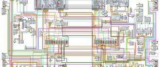
Electrical wiring diagram
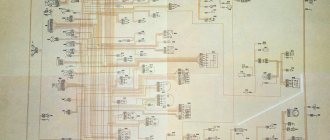
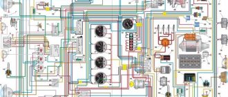
The top picture shows a non-contact version of the car's electrical wiring in color; the bottom picture shows an older model.
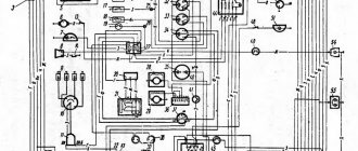
Old style UAZ 3303 wiring diagram
The electrical circuit of the UAZ 3303 generator shown separately is shown above.
The circuit having an ignition system with contacts is taken from 469. There is a radio receiver on the circuit, this is interesting.
Electrical circuit of UAZ 469 similar to 3303 with contact ignition system
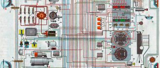
In conclusion, I present another one from an onboard UAZ 33036 that is newer, but not yet fuel-injected.
Source
Schematic features
UAZ 390345, 315314 and analogues in the general wiring have high-quality and reliable components. These are the following types of alarms:
- parking brake;
- level of brake fluid used;
- turning on headlights for high beam;
- switching on for turn signals;
- cooler overheating;
- emergency oil pressure;
- coolant temperature;
- oil pressure and fuel level readings.
All of them are distinguished by a high level of reliability, quality, and durability of use. The wiring includes a microswitch for the carburetor (for model 390994, an injector and the necessary sensors for it), an EPHH valve of the electromagnetic type. The following sections of the circuit are provided for lighting:
- central light switch;
- interior lamp;
- right, left steering column switch;
- fuel level sensors, rear light;
- fog rear lights;
- license plate light;
- reversing lights.
Separately, the electrical circuit of the UAZ 390994 (315314) has such points as power for the cigarette lighter, trailer socket, bimetallic (that is, thermal) fuse. It must be remembered that such wiring for the UAZ 390945 trailer socket is not available on all models, but only on some. If necessary, you can connect additional equipment.
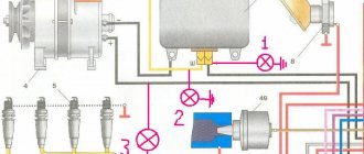
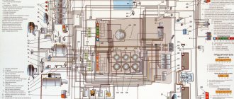
Electrical diagram of a UAZ-39094 car with multifunctional steering column switches
1 – front lamp; 2 – headlight; 3, 4 – fog lights; 5 – headlight; 6 – front lamp; 7 – switch for warning lamp for brake system malfunction; 8 – sound signal; 9 – windshield wiper; 10 – brake light switch; 11 – windshield wiper breaker; 12 – electric washer; 13 – heater resistance; 14 – fog lamp relay; 15, 16 – headlight switching relay; 17 – fuse for fog lights 10 A; 18 – relay for direction indicators and hazard warning lights; 19 – hours; 20 – heater electric motor; 21 – cigarette lighter; 22 – cigarette lighter fuse 16 A; 23 – switch for direction indicators and light signaling; 24 – sound signal button; 25 – wiper switch; 26 – thermal fuse 20 A; 27 – fuse block; 28 – plug socket; 29 – cabin heater switch; 30 – external lighting switch; 31 – rheostat for instrument lighting; 32 – lamp lamp switch; 33 – speedometer; 34 – voltage indicator; 35 – oil pressure indicator; 36 – coolant temperature indicator; 37 – fuel level indicator; 38 – rear fog lamp switch; 39 – control lamp for high beam headlights; 40 – indicator lamp for direction indicators; 41 – indicator lamp for turning on the parking brake; 42 – warning lamp for brake system malfunction; 43 – warning lamp for emergency oil pressure; 44 – warning lamp for emergency coolant temperature; 45 – ignition switch; 46 – ignition switch relay; 47 – control unit EPPH; 48 – fog lamp switch; 49 – alarm switch; 50 – cabin lighting; 51 – generator; 52 – emergency oil pressure sensor; 53 – oil pressure sensor; 54 – coolant temperature sensor; 55 – emergency coolant temperature sensor; 56 – transistor switch; 57 – emergency vibrator; 58 – parking brake warning lamp switch; 59 – additional resistance; 60 – starter relay; 61 – electromagnetic valve EPPH; 62 – unbalance solenoid valve; 63 – microswitch; 64, 65, 66, 67 – spark plugs; 68 – sensor-distributor; 69 – ignition coil; 70 – side repeater; 71 – interior lamp; 72 – starter; 73 – battery; 74 – ground switch; 75 – reverse light switch; 76 – side repeater; 77 – fuel level sensor; 78, 83 – rear lights; 79, 80 – license plate lights; 81 – rear fog lamp; 82 – reversing lamp
Electrical wiring diagram
The top picture shows a non-contact version of the car's electrical wiring in color; the bottom picture shows an older model.
Old style UAZ 3303 wiring diagram
The electrical circuit of the UAZ 3303 generator shown separately is shown above.
The circuit having an ignition system with contacts is taken from 469. There is a radio receiver on the circuit, this is interesting.
Electrical circuit of UAZ 469 similar to 3303 with contact ignition system
In conclusion, I present another one from an onboard UAZ 33036 that is newer, but not yet fuel-injected.
The integrated microprocessor engine control system (CMPSUD) of passenger-and-cargo utility vehicles, UAZ-3741 and UAZ-3909 vans, UAZ-3962 ambulances, UAZ-2206 buses and UAZ-3303 freight vehicles includes an electronic control unit, sensors, actuating electric mechanisms, and diagnostic control malfunction lamp, wiring harness and diagnostic connector.
CMPSUD diagrams of cars of the UAZ-3741, 3909, 3962, 2206 and 3303 families with UMZ-4213, ZMZ-4091 and ZMZ-40911 engines.
On freight-passenger cars of the UAZ-3741, 3909, 3962, 2206 and 3303 models, depending on the engine and its environmental class, a KMPSUD with the following electronic control units and controllers was installed:
— For cars with the UMZ-4213.10 Euro-2 engine — MIKAS-7.2 control unit 291.3763000-11 — For cars with the UMZ-4213.10 Euro-3 engine — MIKAS M10.3 control unit 574.3763000-03 — For cars with the ZMZ-4091.10 Euro engine -3 - control unit MIKAS-11 825.3763001-01 or BOSCH M17.9.7 0 261 S04 795 - For cars with a ZMZ-40911.10 Euro-4 engine - control unit BOSCH M17.9.7 0261 S06 585 for configuration with a mass air flow sensor and BOSCH M17.9.7 0261 S07 322 for equipment with absolute pressure sensor.
CMPSUD diagram of cars of the UAZ-3741, 3909, 3962, 2206 and 3303 families with UMZ-4213.10 Euro-3 engines and the MIKAS M10.3 control unit 574.3763000-03.
Diagram of the KMPSUD wiring harness for cars of the UAZ-3741, 3909, 3962, 2206 and 3303 families with UMZ-4213.10 Euro-3 engines and the MIKAS M10.3 control unit 574.3763000-03.
The composition of the UMZ-4213.10 Euro-3 engine control system with the MIKAS M10.3 control unit, its sensors and actuators are discussed in detail in a separate material.
CMPSUD diagram of cars of the UAZ-3741, 3909, 3962, 2206 and 3303 families with ZMZ-4091.10 Euro-3 engines and MIKAS-11 control unit 825.3763001-01.
The composition of the ZMZ-4091.10 Euro-3 engine control system with the MIKAS-11 control unit, its sensors and actuators are discussed in detail in a separate material.
CMPSUD diagram of cars of the UAZ-3741, 3909, 3962, 2206 and 3303 families with a ZMZ-4091.10 Euro-3 engine and a Bosch M17.9.7 control unit.
The composition of the ZMZ-4091.10 Euro-3 engine control system with the Bosch M17.9.7 control unit, its sensors and actuators are discussed in detail in a separate material.
Electrical diagram of the CMPSUD of cars of the UAZ-3741, 3909, 3962, 2206 and 3303 families with ZMZ-40911.10 Euro-4 engines and a BOSCH M17.9.7 0261 S07 322 control unit.
The composition, sensors and actuators of the control system of UAZ-3741, 3909, 3962, 2206 and 3303 with ZMZ-40911.10 Euro-4 engines and the BOSCH M17.9.7 control unit are discussed in a separate material.
Designations of components and circuits in the diagrams:
A1 — engine control controller (unit); A2 — electric fuel pump module with level sensor; A3 - instrument cluster or panel; A4 - immobilizer (car anti-theft system - APS); A5 - trip computer; A6 — accelerator pedal module (E-gas); A7 — throttle device with electric drive; B1 - throttle position sensor; B2 - mass air flow sensor; B3 - coolant temperature sensor; B4 - air temperature sensor; B5 - knock sensor; B6 - oxygen sensor No. 1; B7 - oxygen sensor No. 2; B8 - rough road sensor; BP1 — intake air absolute pressure sensor; BP2 - emergency oil pressure alarm sensor; BP3 - air conditioner refrigerant pressure sensor; BR1 — synchronization sensor (crankshaft position); BR2 — phase sensor (camshaft position); BV1 - vehicle speed sensor; F1-F4 - spark plugs for cylinders 1-4; FU1-FU6 - fuse; HL1 - MIL lamp for engine diagnostics; HL2 — IMMO lamp for immobilizer status (ALS unit); GB1 - rechargeable battery; KA1 - main relay; KA2 - electric fuel pump relay; KA3, KA4 - relay for electric fans No. 1 and No. 2 for engine cooling; KA5 - air conditioning compressor clutch relay; L1 – immobilizer transceiver antenna; M1 - electric fuel pump; M2, M3 - electric fans 1 and 2; PF1 - tachometer; PS1 - coolant temperature indicator; TV1, TV2 - two-terminal ignition coil; TV3 - ignition module with two-terminal coils; TV4-TV7 - individual ignition coils; TV8 – four-terminal ignition coil; W1-W4 - high-voltage ignition wires; SA1 - ignition switch; SA2—mass switch; SA3 - air conditioner switch; SA4 — two-channel brake pedal switch; SA5 – clutch pedal switch; XS1 — diagnostic connector; XS2 — nozzle connector; Y1-Y4 — gasoline injectors; Y5 — additional air regulator (idle speed); Y6 — adsorber purge valve; Y7 - electric coupling of the air conditioning compressor; * — the component can be installed as an additional kit.
Electrical circuits on the diagrams:
“15” - circuit from the ignition switch; “30” - battery power circuit; “Um” - power circuit from the main relay of the system; “Ue” - power circuit from the electric fuel pump relay; GNP - power ground of the controller output stages; GNI - “ground” for power ignition channels; GND - “ground” for the logical and digital circuits of the controller; GNA - “ground” for the signal (analog) circuits of the controller.
The remaining circuits are named after the terminals of the electronic control unit. Do not operate the engine with the diagnostic lamp on. Constant lighting of the lamp indicates the presence of malfunctions in the engine control system.
If there are malfunctions, the control system automatically switches to emergency operation mode. Starting a cold engine worsens, exhaust toxicity and fuel consumption increase. It is imperative to diagnose the CMPSUD and eliminate any malfunctions that have arisen.
Source
Platform for conveyor models
The “Loaf”, which became famous, thanks to its all-metal body, the “452” model served as a platform for the creation of an entire line of vehicles:
- UAZ 2206 – a minibus designed for 11 people;
- UAZ 3962 – vehicle for emergency medical services;
- UAZ 396255 - a civilian modification of an ambulance for the needs of rural areas;
- UAZ 39099 – promoted under the name “Farmer”. Designed for 6 passengers and 450 kg of cargo;
- UAZ 3741 – a van for transporting 2 passengers and 850 kg of cargo;
- UAZ 3303 – an onboard vehicle with an open body;
- UAZ 3904 is a cargo-passenger version that combines the convenience of an all-metal body for passengers and an open body for cargo.
For reference: in all modifications, the electrical wiring of the UAZ 2206 is taken as a basis, from which, for each model, unused components that perform certain functions in the car interior have been removed.
Electrical diagram of a UAZ loaf with a carburetor engine
I looked for the schematic and found it in good quality so it wouldn’t get lost. UAZ–3741, 3909, 3962, 2206
How is the 452 wiper motor connected?
diagnostic connectors OBDII and UAZ / GAZ
I have a 1989 car, originally it had a contactless ignition system. Later it was converted to contact, which in principle I do not regret. And each has its own pros and cons. We’re not talking about them. I had to use the old-style UAZ 3303 wiring diagram, of course, with a carburetor.
The plant immediately warns about the possibility of making changes to the electrical circuit. Since the car is almost 30 years old, there are such changes. I will give several diagrams with contact and non-contact ignition systems for different UAZ vehicles. But since in those days there were no special differences, I consider them similar with some differences.
basic information
Fuses in a UAZ Bukhanka car are located in a special mounting block, which in turn is located in the air inlet box on the left side of the vehicle. The mounting block includes all the most important sections of electronic circuits, while supplying them with the necessary fuses and relays. The fuse box of the UAZ Bukhanka car consists of two lines with fuses and this entire structure is secured with a nut to the vehicle body. If you decide to remove the fuse lines, you will need to disconnect the battery.
The main elements of the electronic circuit include:
- Accumulator battery;
- Electronic fuel pump;
- Fuel mixture purification filter;
- Injectors;
- Engine control unit;
- Electronic ignition coil;
- Spark plugs;
- Idle speed sensor;
- Crankshaft sensor;
- Air damper sensor;
- Tachometer;
- Fan motor cooling the radiator;
- Electronic fan motor control relay;
- An indicator that monitors engine performance;
- Diagnostic connector.
Wiring diagram UAZ Bukhanka
If any failure of electronic equipment occurs, the current in the node that is responsible for this device will increase, resulting in a short circuit. The wire through which the current passes to the fuse burns out and melts, as a result of which the circuit breaks and the device turns off, but its integrity is maintained. That is, thanks to fuses, the main parts are protected from overheating in the event of a short circuit.
How to properly remove and install the mounting block?
If the electrical circuit is made with high quality, it will greatly facilitate the process of installing and removing electronic equipment. So, the algorithm for removing the mounting block:
- Disconnect the wiring from the negative terminal of the battery;
- Open the hood and remove the cover from the fuse and relay box. To do this, you need to press out 4 plastic latches;
- Move the rubber cover;
- Disconnect the upper block of the wiring harness from the block;
- We unscrew the 2 nuts that secure the block;
- We take out the block from the compartment, which is located in front of the windshield;
- We disconnect the lower blocks of the wiring harnesses from the block;
- Install fuses and relays in reverse order.
Repairing the mounting block involves replacing printed circuit boards. So, the algorithm for repairing the mounting block:
- Remove the mounting block;
- Remove the 8 screws that secure the bottom cover;
- Using a screwdriver, open the bottom cover;
- We check the condition of the tracks along which the current passes and the quality of soldering. If defects are detected, they must be eliminated, but if this is not possible, then completely replace the unit;
- Install the mounting block in reverse order.
Characteristics
Despite its simplicity, the UAZ-469 already in those years had two fuel tanks and excellent cross-country ability. It was possible to overcome fords, obstacles and bad roads on this SUV without any modifications, but today tuning of various UAZs, including the 469 model, is becoming increasingly popular. Amateurs equip cars with larger wheels with mud tires, lift the car and install more powerful engines. True, with the latter option, all the simplicity of the design fades into the background, because you have to completely redo the entire electrical wiring of the cars. Nevertheless, the popularity of the car is only growing.
Improvement of electrical equipment
Most car enthusiasts will agree that an equally important thing is the central locking on the UAZ. The lock for the UAZ Bukhanka can be easily purchased at any auto parts store and installed on the vehicle without any problems.
Another “upgrade” for this car is an electric engine fan. An electric fan is a standard part for most modern cars. However, in older models such a device was not installed. Many car enthusiasts have already become convinced of the usefulness of such a wiring part as an electric fan, so it is often installed on the Bukhanka, especially since it can be easily purchased at any car store.
In addition, UAZ 452 owners often change standard mirrors. Since this car is often used in rather extreme conditions, heated mirrors would obviously be useful. Especially for drivers in cold climates. Electrically heated mirrors are quite simply installed on the Bukhanka, since the electrical circuit of the UAZ 452 allows such improvements.
Injector, dashboard, electric fan, heated mirrors - after so many innovations, the UAZ wiring diagram is undergoing changes. And for the smooth operation of all the above improvements, a good generator will not hurt. The standard UAZ 452 generator cannot be called bad, however, according to statistics, most owners still decide to install another generator.
To do this, you can take a generator from any other brand of car. For example, generators from Volkswagen, Nissan and other cars are often installed on Bukhanka. A generator is an important element of electrical wiring, so if you decide to seriously improve the electrical equipment of the UAZ 452, then a new generator may be needed.
Source of the article: https://kalina-2.ru/remont-vaz/shema-jelektrooborudovanija-uaz-452-cvetnaja-s
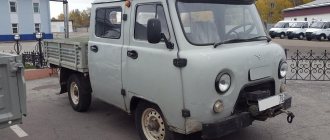
Meet UAZ 452
The car was a cargo-passenger version of an off-road vehicle with a 4x4 wheel arrangement. The Ulyanovsk Automobile Plant mastered production of the model back in 1965.
You can evaluate its capabilities by watching the following video:
The UAZ 452 is capable of transporting cargo weighing up to 700 kg in the back. In addition, it can tow a trailer weighing 850 kg. The vehicle became very popular not only in Russian off-road conditions, but was also successfully used in large cities in various capacities (pictured in the article).
- Like a traffic police car;
- As a fire engine;
- Ambulance car;
- Grocery store;
- Utility vehicle, etc.
Electronic components
The electrical wiring of the UAZ 452 was a simple single-wire circuit.
Structurally, it had the following solutions:
- The role of the second wire was played by the metal body and the components and assemblies attached to it;
- All electronic components and actuators had a “-” displayed on the housing. The cost of such a solution justified the imperfection of the scheme.
For reference: The instructions provided for regular checking of contacts. When oxidized, they should have been cleaned with sandpaper.
Power unit
The engine compartment is located directly inside the car, as this is due to its design.
Access to components and assemblies is also provided from the passenger compartment by removing the cover, which:
- Provided protection for the driver and passengers from the penetration of exhaust gases;
- Protected from dust and dirt;
- Served as an additional heating element (passive - from heating).
The previously used engine from Pobeda was replaced with a more modern engine from the 21st Volga. This was facilitated by the launch of a production line at the Zavolzhsky Motor Plant in 1964.
Note! Despite some skepticism regarding the inconvenience of servicing a cabover car with your own hands, years of operation have proven that there are no difficulties.
Passive vehicle safety
The design of the "Baton" with a cabover layout also initially raised a number of questions regarding safety. However, a series of crash tests conducted back in 1971 at the Dmitrov test site proved that in most emergency situations the driver and passengers of the UAZ 452 have a chance to avoid injury.
What is included in the electrical circuit?
What features do automotive electrics have on old cars produced by the Ulyanovsk Automobile Plant?
Electronic components
The electrical circuit of the UAZ 452 itself is quite simple - single-wire.
By its design, the wiring diagram of a UAZ390995 or other model is characterized by the following solutions:
- The vehicle body is used as the mass.
- Any electrical equipment of the old-style circuit on a UAZ 409 or other model, as well as actuators, are equipped with a negative terminal, which is connected to the car body. According to experts, in general this scheme is imperfect.
According to the operating instructions for electrical equipment, the driver must periodically diagnose the condition of the integrity of the contacts. We are also talking about their oxidation. If the driver notices the presence of oxidation on the terminals, he should treat them using fine-grained sandpaper.
Engine compartment
In this case, the engine compartment is located directly in the passenger compartment in accordance with the design of the car.
Access to the electrical circuit and other mechanisms and assemblies is made from the interior, as a result of dismantling the cover, which:
- Designed to protect the motorist and passenger from exhaust gases entering the cabin.
- Allows you to protect the car interior from the penetration of dirt and dust.
- Performs the function of an additional heating device, in particular passively, as a result of heating.
Engine compartment of an AUZ car
Previously, the UAZ 396255 and other models with a carburetor used an engine from the legendary Pobeda, which was later replaced with a more improved and modern unit. In particular, it means a Volga engine. This decision at one time, back in 1964, was facilitated by the serial launch of a production line at the ZMZ enterprise. Despite the fact that many domestic car enthusiasts claim that the UAZ 390994 injector circuit in the engine compartment is located in an inconvenient place due to the lack of a hood, this is not so. Decades of operation have proven that the absence of a hood in no way affects the diagnosis and maintenance of the car.
Passive safety
The very design of the domestic Loaf with the absence of a hood at first raised many questions in terms of the safety of the driver and passengers. As a result of several dozen crash tests that were carried out back in the early 70s of the last century, it was revealed that the car is no less safe when compared with other domestic cars. As the results showed, in the event of an accident, both the driver and passengers of the car have a good chance of avoiding injury in an accident.
Release 1965 - 1984
If we talk about the beginning of production, then that UAZ 452 electrical equipment circuit lasted on the assembly line until 1984. During this period, many details in the circuit were borrowed from other models. Also, quite a large number of details could be called experimental. However, as the future has shown, such simplicity resulted in extreme reliability during operation.
In those years, it was quite a difficult task to find the necessary elements and parts. This problem was especially pressing in ignition and lighting systems. Therefore, the solution was to borrow parts from predecessors. So, a foot light switch was taken from GAZ 69.
She got the Bukhanka's headlights from the GAZ 24. The ignition system was copied with minor changes from the Volga. Therefore, it is not surprising that the GAZ 452 manufacturers also borrowed the engine from the Volga. As for the electrical circuit, everything was very primitive and simple, but at the same time practical and reliable. In addition, the price of the issue clearly justified such simplicity.
The electrical circuit of old UAZs was not ideal. The instructions of those years even provided for cleaning the contacts with sandpaper in case of oxidation. This approach raised some doubts about the safety of the electrical wiring design. And the UAZ electrical wiring itself in those years was a simple single-wire circuit.
troubleshooting
On any domestic car, problems periodically arise in the operation of electrical equipment. If you notice that the UAZ wiring is not working correctly, you need to diagnose it and check all the elements. If there are any malfunctions in the operation of electronic devices, first of all you need to check whether the fuses in the mounting block have burned out. If everything is fine with these elements, but the equipment still does not function, for example, if we talk about optics, then you need to check whether the light bulbs are working. If the lamps themselves are working, it is necessary to ring the electrical part using a tester (the author of the video about ringing is Ramil Abdullin).
If the Loaf refuses to start at all, you need to do the following:
- First of all, check the functionality of the battery.
- With the battery charged, use a tester to test the circuit from the coil to the generator; often the reason for the inability to start the engine is breaks in the wiring. If there are breaks, the wires should be changed. If there is oxidation on the contacts, they should be cleaned.
- Starting the power unit will be impossible if there is no spark. To diagnose the presence of a spark, remove the high-voltage cable from the spark plug and bring it to the body. When you try to start the engine, a spark should jump between the cable and the body.
- If there is no spark, the problem may be carbon deposits and deposits on it. By the way, carbon deposits are often the cause of unstable engine operation and tripping. To get rid of such a malfunction, it is advisable to clean the spark plugs; step-by-step instructions for this process are presented.
The UAZ-452 has received a variety of affectionate nicknames over the years of operation: “Loaf” and “Loaf” - for its external resemblance to a bread brick, “Tablet” - for reliable service in medical organizations. It is noteworthy that its design and individual systems - transmission, body or wiring diagram of the UAZ 452 turned out to be quite durable. Perhaps this was the only car in those years capable of reaching the most remote places for humanitarian purposes.