It would not be an exaggeration to call the legendary model “452” the ancestor of a whole family of multi-purpose utility vehicles under the UAZ brand. This is true, and experts are well aware that the wiring diagram of the UAZ 3962, components and transmissions of the model 3904, as well as other modifications, are unified with the “452”.
UAZ wiring diagram with conventional steering column switches
All world manufacturers of passenger cars and utility vehicles are developing in a similar way:
- A successful design serves as the basis for a whole family of cars;
- Constant refinement and modernization allows us to update the model range;
- Unification of parts and components reduces the cost of creating new cars.
The famous “Polbaton” - photo of the UAZ 3904 model
For reference: When car owners communicate with each other about the “civilian” version of a particular UAZ unit, this is true. Initially, “452” was created by order of the Ministry of Defense as a vehicle accompanying tank columns on the march. And for use on public roads, the car was modernized.
Find out also about the features of replacing UAZ 3303 wiring.
Blog about UAZ
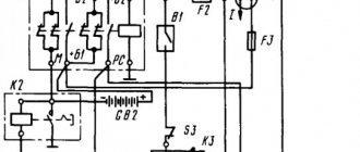
The all-encompassing microprocessor engine control system (CMPSUD) of passenger-and-cargo passenger cars, UAZ-3741 and UAZ-3909 vans, UAZ-3962 ambulances, UAZ-2206 buses and UAZ-3303 freight vehicles contains an electrical control unit, sensors, actuating electric mechanisms, and diagnostic control malfunction lamp, wiring harness and diagnostic connector.
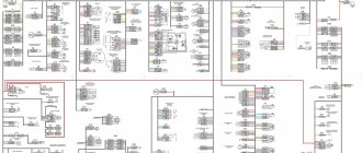
CMPSUD diagrams of cars of the UAZ-3741, 3909, 3962, 2206 and 3303 families with UMZ-4213, ZMZ-4091 and ZMZ-40911 engines.
On cargo-passenger cars of the wagon layout of the UAZ-3741, 3909, 3962, 2206 and 3303 models, depending on the engine and its environmental class, KMPSUD was installed with subsequent electrical control units, controllers:
- On a car with a UMZ-4213.10 Euro-2 engine - MIKAS-7.2 control unit 291.3763000-11 - On a car with a UMZ-4213.10 Euro-3 engine - MIKAS M10.3 control unit 574.3763000-03 - On a car with a ZMZ-4091.10 Euro engine -3 - control unit MIKAS-11 825.3763001-01 or BOSCH M17.9.7 0 261 S04 795 - On cars with a ZMZ-40911.10 Euro-4 engine - control unit BOSCH M17.9.7 0261 S06 585 for configuration with a mass air flow sensor and BOSCH M17.9.7 0261 S07 322 for equipment with absolute pressure sensor.
CMPSUD diagram of cars of the UAZ-3741, 3909, 3962, 2206 and 3303 families with UMZ-4213.10 Euro-3 engines and a control unit MIKAS M10.3 574.3763000-03.
Diagram of the KMPSUD wiring harness for cars of the UAZ-3741, 3909, 3962, 2206 and 3303 families with UMZ-4213.10 Euro-3 engines and the MIKAS M10.3 control unit 574.3763000-03.
The composition of the control system for UMZ-4213.10 Euro-3 engines with the MIKAS M10.3 control unit, its sensors and actuators, are carefully reviewed in a separate material.
CMPSUD diagram of cars of the UAZ-3741, 3909, 3962, 2206 and 3303 families with ZMZ-4091.10 Euro-3 engines and MIKAS-11 control unit 825.3763001-01.
The composition of the control system for ZMZ-4091.10 Euro-3 engines with the MIKAS-11 control unit, its sensors and actuators, are carefully reviewed in a separate material.
CMPSUD diagram of cars of the UAZ-3741, 3909, 3962, 2206 and 3303 families with a ZMZ-4091.10 Euro-3 engine and a Bosch M17.9.7 control unit.
The composition of the control system for ZMZ-4091.10 Euro-3 engines with the Bosch M17.9.7 control unit, its sensors and actuators, are carefully reviewed in a separate material.
Electronic circuit of the KMPSUD of cars of the UAZ-3741, 3909, 3962, 2206 and 3303 families with ZMZ-40911.10 Euro-4 engines and a BOSCH M17.9.7 0261 S07 322 control unit.
The composition, sensors and actuators of the control system of UAZ-3741, 3909, 3962, 2206 and 3303 with ZMZ-40911.10 Euro-4 engines and the BOSCH M17.9.7 control unit are discussed in a separate material.
Designations of components and circuits on diagrams:
A1 — engine control controller (unit); A2 — electric fuel pump module with level sensor; A3 - composition or device panel; A4 - immobilizer (car anti-theft system - APS); A5 — route computer; A6 — gas pedal module (E-gas); A7 — throttle device with electric drive; B1 - throttle position sensor; B2 - mass air flow sensor; B3 - cooling water temperature sensor; B4 - air temperature sensor; B5 - knock sensor; B6 - oxygen sensor No. 1; B7 - oxygen sensor No. 2; B8 - rough road sensor; BP1 — intake air absolute pressure sensor; BP2 - emergency oil pressure alarm sensor; BP3 - air conditioning refrigerant pressure sensor; BR1 — synchronization sensor (crankshaft position); BR2 — phase sensor (camshaft position); BV1 - vehicle speed sensor; F1-F4 - spark plugs for cylinders 1-4; FU1-FU6 - fuse; HL1 - MIL lamp for engine diagnostics; HL2 — IMMO lamp for immobilizer status (ALS unit); GB1 - rechargeable battery; KA1 - main relay; KA2 - electric fuel pump relay; KA3, KA4 - relay for electric fans No. 1 and No. 2 for engine cooling; KA5 — air conditioning compressor clutch relay; L1 – immobilizer transceiver antenna; M1 - electric fuel pump; M2, M3 - electric fans 1 and 2; PF1 - tachometer; PS1 - cooling water thermometer; TV1, TV2 - two-terminal ignition coil; TV3 - ignition module with two-terminal coils; TV4-TV7 - personal ignition coils; TV8 – four-terminal ignition coil; W1-W4 - high-voltage ignition wires; SA1 - ignition switch; SA2—mass switch; SA3 - air conditioner switch; SA4 — two-channel brake pedal switch; SA5 – clutch pedal switch; XS1 - diagnostic connector; XS2 — nozzle connector; Y1-Y4 — gasoline injectors; Y5 — additional air regulator (idle speed); Y6 — adsorber purge valve; Y7 — electric coupling of the air conditioner compressor; * — the component can be installed as an additional kit.
Electronic circuits on the diagrams:
“15” - circuit from the ignition switch; “30” - power supply circuit from the battery; “Um” - power circuit from the system head relay; “Ue” - power circuit from the electric fuel pump relay; GNP - power ground of the controller output stages; GNI - “ground” for power ignition channels; GND - “ground” for the logical and digital circuits of the controller; GNA - “ground” for the signal (analog) circuits of the controller.
Other circuits are named after the terminals of the electrical control unit. It is not allowed to operate the engine with a flaming diagnostic lamp. Constant lighting of the lamp indicates the presence of defects in the engine control system.
If there are defects, the machine control system switches to emergency operation mode. Starting a cold engine becomes worse, the toxicity of exhaust gases and fuel consumption increase. It is imperative to diagnose the CMPSUD and remove any malfunctions that have arisen.
Source: auto.kombat.com.ua
Technical characteristics and design features of the ZMZ 409 engine
We study the electrical diagram of the VAZ 21074
The ZMZ 409 gasoline engine, equipped with a microprocessor-controlled direct injection system, is based on the cast-iron cylinder block of the ZMZ 406 model unit. The power plant was created specifically to equip UAZ vehicles, as well as Volga (experimental and small-scale versions). It differs from the base engine by an increased piston stroke and modernized pistons, which made it possible to retain the same connecting rods. Depending on the software version, the motors meet Euro 2/3 or 4 requirements. The latest modifications of the motor comply with Euro 5 standards and have modified power and torque curves.
The powertrain serial number, which is the vehicle's VIN number, is located on the left side of the engine block above the front mount mount.
Technical characteristics of the power unit:
- block design - 4-cylinder in-line;
- number of valves per cylinder - 4 (2 for intake, 2 for exhaust);
- cylinder diameter - 95.5 mm;
- piston stroke - 94 mm;
- working volume - 2693 cubic meters. cm;
- compression ratio - 9;
- The order of flashes in the cylinders is 1:3:4:2;
- maximum power (version for UAZ “Bukhanka”) - 112 hp. With. at 4250-4400 rpm;
- torque - no less than 198 N/m at 2500 rpm;
- fuel type - unleaded gasoline with an octane rating of 92 or more;
- direction of rotation of the crankshaft (from the pulley side) is right;
- type of cooling system - liquid, forced type;
- crankcase ventilation system - forced, closed type, operates from a vacuum inside the intake manifold;
- engine weight (with attachments) - 190 kg.
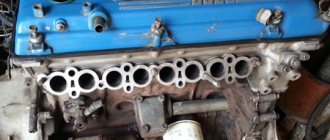
Main features of the engine design:
- the working mirrors of the cylinders are made directly in the material of the cast iron block, without the use of liners;
- main bearing caps are not interchangeable, since the parts are processed together with the block;
- the front cover of the camshaft supports is the same for the intake and exhaust;
- the timing gear bearing caps are machined together with the head, so they cannot be swapped;
- Hydraulic play compensators are installed in the valve drive;
- some engines have intake and exhaust camshafts with identical cam profiles;
- the pistons have recesses on the bottom that prevent contact with the valves in the event of a violation of the valve timing;
- the valves and mounting springs are identical to those used on the engines of the VAZ-2108 car.
To complete the UAZ “Bukhanka” vehicles, several engine modifications were supplied, differing in attachments.
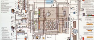
Scheme UAZ-390995, -220695, -396255 Loaf. Injector.
Scheme UAZ-390995, -220695, -396255 Loaf. Injector.
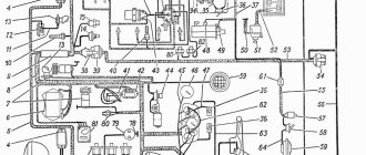
Electrical diagram of the car.
1 , 50 – front lights; 2 – wind window washer electric pump; 3 – windshield wiper; 4 – windshield wiper and washer switch; 5 – rear fog lamp switch; 6 – alarm switch; 7 – electric motor of the additional heater fan (installed on UAZ-220695, UAZ-390995 and UAZ-396255); 8 , 47 – headlights; 9 – additional resistance of the main heater; 10 – main heater fan electric motor; 11 – main heater fan electric motor switch; 12 – additional resistance of the additional heater (installed on UAZ-220695, UAZ-390995 and UAZ-396255); 13 – switch for the additional heater fan electric motor; 14 – fuel module; 15 , 56 – side direction indicator lights; 16 , 46 – rear dimensions; 17 – brake water level sensor; 18 – sound signal; 19 – sound signal switch; 20 – fog lamp relay; 21 – external lighting switch; 22 – signaling unit; 23 – speedometer; 24 – interior heater motor fuse; 25 – generator; 26 – starter; 27 – battery; 28 – ground switch (depending on the configuration); 29 – license plate light; 30 – fog lamp; 31 – direction indicator switch; 32 – thermal fuse; 33 – composition of devices; 34 – switch for fuel level sensors in tanks (not installed on UAZ-330395, UAZ-330365, UAZ-390945 vehicles); 35 – emergency oil pressure sensor; 36 – oil pressure sensor; 37 – starter relay; 38 – reversing lamp; 39 – brake light switch; 40 – connecting panel; 41 – switch of the electric motor of the cooling water circulation pump; 42 – electric motor of the cooling water circulation pump; 43 – emergency cooling water temperature sensor; 44 – fuel level sensor; 45 – speed sensor; 48 – turn signal and hazard warning relay; 49 – reverse light switch; 51 – foot switch for headlights; 52 – fuse block; 53 – socket for connecting additional electrical equipment; 54 – ignition switch; 55 – brake system status indicator switch; 57 , 59 – interior lamps; 58 , 60 – interior lamp switches.
Additional elements of the “Loaf” electrical system
The following elements can be installed in the Loaf cabin:
- Fuse block.
- Turn signal control relay.
- ABS indicator lamp controller.
- Turning on the high beams.
- Low beam control relay.
- Ensuring intermittent wiper movement.
- Rear fog lamp controller.
- Starter circuit control.
Arrangement of elements in the cabin
If ABS is used, an additional fuse box is installed on the machine, which includes:
- protective element of power circuits, designed for a current of 40A (position I);
- 25A wiring protection device (position II).
Location of fusible links of the ABS system
Symbols on the diagram:
- Block.
- Direct fuses.
When installing an anti-lock braking system, the following components are included in the electrical circuit:
- hydraulic unit with controller A1;
- sensors for determining the speed of rotation of the front and rear wheels - B1/B2 and B3/B4, respectively;
- acceleration sensor B5;
- ABS control LED on the instrument panel, indicating a system malfunction;
- EBD indicator of hydraulic module failure;
- Brake pedal position sensor BLS.
Schematic diagram of ABS on the “Loaf”
The main fuse box used on cars is:
| Number on the diagram | Denomination, A | Purpose |
| F1 | 10 |
|
| F2 | 10 |
|
| F3 | 10 |
|
Diagram of the main mounting block
Medical versions of the Loaf are equipped with an extended fuse block to protect additional equipment. There are also cars equipped with heated front seats at the factory. These machines have additional wiring harnesses.
Self-installation of electronic ignition on a UAZ was demonstrated by the author of the video, Alexander Grushevsky.
Wiring diagram for a loaf with a carburetor engine
To connect electrical appliances to the system of a car with a carburetor, an old standard circuit is used - a loaf designed for UAZ cars from 1954 to 1984.
Why might a wiring diagram for such a car be useful? The need for notes on wiring in a frame may seem not only if a certain defect that interferes with the operation of the vehicle is corrected, but also when the wiring is laid again.
It is worth keeping in mind that there are two circuits for a car with a carburetor engine. The first is the usual one, which does not have an electric carburetor control unit (this element appeared after 1984 and does not fit into old circuits).
2nd – slightly more difficult (taking into account the connection of the carburetor control unit). Such a scheme must be used if it is necessary to connect to the operation of all electrical systems of the car, and not just the ignition and the minimum required for driving the vehicle.
To conduct wires according to a simplified scheme, it is enough to stretch a wire from the battery through the ignition switch to create a spark, and the second through the relay and the starter button to ensure the ability to start the engine.
If the car's generator does not have a built-in voltage regulator, then it must be purchased and connected to the system.
Release 1965 - 1984
If we talk about the beginning of production, then that UAZ 452 electrical equipment circuit lasted on the assembly line until 1984. During this period, many details in the circuit were borrowed from other models. Also, quite a large number of details could be called experimental. However, as the future has shown, such simplicity resulted in extreme reliability during operation.
In those years, it was quite a difficult task to find the necessary elements and parts. This problem was especially pressing in ignition and lighting systems. Therefore, the solution was to borrow parts from predecessors. So, a foot light switch was taken from GAZ 69.
She got the Bukhanka's headlights from the GAZ 24. The ignition system was copied with minor changes from the Volga. Therefore, it is not surprising that the GAZ 452 manufacturers also borrowed the engine from the Volga. As for the electrical circuit, everything was very primitive and simple, but at the same time practical and reliable. In addition, the price of the issue clearly justified such simplicity.
Wiring diagram for a loaf with an injection engine.
When repairing wiring in such a car, it is difficult to find a ready-made connection diagram - the manufacturer did not include it in the instruction manual.
It is believed that the connection diagram for electrical appliances in UAZ loaf cars with an injection engine is actually one hundred percent consistent with the diagram that is used in a car with a carburetor, but in reality they differ.
To solve car control problems related to wiring, 2 connection schemes are used - the usual one for a loaf with a carburetor engine and the injection one for the GAZ - 69 “Kozel”.
Combining the information from these two diagrams allows you to repair or reinstall the wiring in the injection unit.
Instead of a circuit diagram for an injection GAZ-69, a circuit diagram for an electrical engine control system can be used, so drivers recommend taking it with them along with a wiring diagram for a carburetor loaf engine.
These sources allow you to manage the wiring of the injection loaf throughout the car, but for some electrical components, if they are not provided for in the usual wiring diagram.
In this case, it is worth turning to special forums - the most experienced owners of loaves can not only give a hint for solving the problem that has arisen, but also share the circuit that is missing for this, if their car is the same model as the faulty one.
Source: buhanka-uaz.ru
UAZ-390945 Farmer
The primitive instrument cluster has sunk into oblivion. Now in the center of the front panel (it is still old-school, metal) there is a speedometer, which contains a liquid crystal display - secondary data is displayed on it. Along the edges of the speedometer there is a 12-volt socket and a slot for a single-din audio system. Below is a push-button lighting control unit, which replaced the antediluvian retractable switch.
Ulyanovsk residents decided not to stop there and just go for a walk! — abandoned the ancient “bone” steering wheel in favor of a plastic one that was more comfortable to grip. And under it they installed a pair of modern steering column switches. Before there was one, a tractor type; it took incredible effort to flip it. Relays and fuses no longer play hide and seek - they are combined in a single block. Trifles? An unpretentious client will be happy with these little things that make the car more convenient.
As before, the lump of the engine compartment rises in the middle of the cabin. But if previously it was covered with a thin layer of leatherette, now the surface is covered with carpet, which insulates much better from noise. For the sake of silence in the cabin, the ceiling was covered with needle-punched material: the sound passes through the holes and dissolves there. But this is in theory - but in reality? I’ll check now, fortunately I have a Farmer with a two-row cab.
Stall if you can
Description of the electrical circuit on the UAZ Bukhanka
One of the most common problems with Russian cars is the breakdown of some electronic devices; an electrical diagram will help you figure this out. The only solution to this problem for us will be to check the condition of the fuses. The topic of this article will be the electrical circuit of the UAZ Bukhanka car on an injector type engine.
So, this article provides answers to these fairly common questions:
- What is the electrical circuit on a UAZ Bukhanka car with an injector type motor?
- How does the electrical circuit of the UAZ Bukhanka car work?
- Where are the fuses located on a UAZ Bukhanka injector type motor?
- Repair of the mounting block.
Maintenance and repair
This is what the UAZ distribution box (“loaf”) is like. Its design and repair are simple, and it is unpretentious in maintenance, as evidenced by reviews from the owners. It is recommended to regularly check the oil level and inspect each fastener. It is also necessary to lubricate the axles of the levers and adjust the front linkages. This box has no other settings.
The transfer case of the UAZ-452 is very popular among fans of off-road vehicles. Reviews about her are only positive. It is extremely easy to repair and maintain, and spare parts can be purchased now.
The UAZ-452 was originally created for the Soviet armed forces as a medical service vehicle, where it was therefore dubbed the “tablet” (the civilian nickname is “loaf”).
Therefore, the design of the mechanisms, including the transfer case, is simplified as much as possible.
During operation, the entire transmission system is unpretentious, which is confirmed by half a century of practice. The only recommendation from the manufacturer is to periodically check the oil level and check the fasteners.
In addition, if necessary, the front linkages should be adjusted and the lever axles should be lubricated on a preventive basis. This mechanical unit, including bearings, does not require any further maintenance or adjustment.
basic information
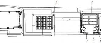
Fuses in a UAZ car The loaf is placed in a special mounting block, and it, in turn, is placed in the air supply box on the left side of the vehicle. The mounting block contains all the important sections of the electrical circuits, while providing them with suitable fuses and relays. The fuse block of the UAZ Bukhanka car consists of two lines with fuses and this entire system is secured with a nut to the vehicle body. If you decide to remove the fuse lines, you will need to disconnect the battery.
The main elements of the electrical circuit include:
- Accumulator battery;
- Electric fuel pump;
- Fuel consistency filter;
- Injectors;
- Engine control unit;
- Electric ignition coil;
- Spark plug;
- Idle speed sensor;
- Crankshaft sensor;
- Air damper sensor;
- Tachometer;
- Fan motor cooling the radiator;
- Electric fan motor control relay;
- An indicator that monitors the performance of the motor;
- Diagnostic connector.
Electrical circuit of the UAZ Bukhanka
If there is any breakdown of the electrical equipment, the current strength will increase in the node that is responsible for this device, as a result of which a short circuit occurs. The wire through which the current passes to the fuse burns out and melts, as a result of which the circuits break and the device turns off, but at the same time its integrity is preserved. In other words, thanks to fuses, the main parts are protected from overheating in the event of a short circuit.
Features of the model and its equipment
The wiring diagram still amazes with its quality. The legal successor of this vehicle was another model 31514, which began production in 1993 and immediately won a circle of its admirers. The new models are significantly different from the previous ones. Not only has the design been improved, but so has the wiring. For example, the electrical circuit of the UAZ 390994, the injector of which could cause inconvenience, did not have a special temperature sensor. New models have contactless ignition. The node includes:
- low voltage ignition coil;
- electronic transistor switch;
- distributor, i.e. sensor-distributor;
- electrical additional resistance;
- special emergency breaker;
- fuses (unit installed).
For example, type 390994, whose injector caused problems at high speeds, did not have such high-quality and sophisticated wiring. And the disadvantage of such a network element does not ensure the closure of the damper for the intake manifold. Servicing such a system is inconvenient; the absence of just one sensor is what makes 390994, whose injector is so “problematic,” not so in demand. The situation was resolved by using a better system and additional cables.
UAZ wiring diagram: individual modifications with multifunctional control
Did you like the article? Look for new thoughts on necessary auto tips in our channel. Subscribe to us in Yandex.Zen. Subscribe.
It would not be an exaggeration to call the legendary model “452” the ancestor of a whole family of multi-purpose cargo-passenger vehicles under the UAZ brand. This is true, and experts are well aware that the wiring diagram of the UAZ 3962, components and boxes of the 3904 model, as well as other modifications, are unified with the “452”.
All world manufacturers of passenger cars and utility vehicles are developing using a similar method:
- A successful system serves as the basis for an entire family of cars;
- Constant refinement and modernization allows us to update the model range;
- The unification of parts and components reduces the costs of creating new cars.
For reference: When, in a conversation among themselves, car owners mention the “civilian” version of one or another UAZ unit, this corresponds to reality. Initially, “452” was created by order of the Ministry of Defense as a vehicle that would guide tank columns on the march. And for implementation on public roads, the car was modernized.
UAZ-390945 Farmer
Compared to the previous Farmer, the new one starts calmly, without convulsions or shudders - it picks up speed happily. The clutch, however, grabs at the very top. But it’s okay, I got used to it. I also got used to the sweeping shifts of the five-speed manual.
The ride quality and energy efficiency of the suspension are impressive. The Farmer passes even the monstrous-looking pit with barely noticeable swaying. That’s why in regions with bad roads Ulyanovsk cars are so valued! They also love UAZs for their excellent cross-country ability. I was running around like crazy through the back streets of the factory territory in order to park the car. In vain. He overcame all the proposed obstacles using only rear-wheel drive. I only had to connect the front axle a couple of times, and it didn’t even come down to downshifting.
For those for whom the all-terrain qualities of the UAZ are not enough (there are some), starting in July they will be offered a version with a rear cross-axle differential lock. A jeeper's dream! It will apparently raise the level of cross-country ability to a very high level. I hope in the summer, when a car with a lock falls into our hands, we will find a worthy obstacle for it.
Platform for conveyor models
The “Loaf”, which became famous, thanks to its all-metal body, the “452” model served as a platform for the creation of an entire line of vehicles:
- UAZ 2206 – a minibus designed for 11 people;
- UAZ 3962 – car for emergency medical services;
- UAZ 396255 – civilian modification of an ambulance for the needs of rural areas;
- UAZ 39099 – promoted under the name “Peasant”. Designed for 6 passengers and 450 kg of cargo;
- UAZ 3741 – a van for transporting 2 passengers and 850 kg of cargo;
- UAZ 3303 – flatbed car with an open body;
- UAZ 3904 is a cargo-passenger version that combines the convenience of an all-metal body for passengers and an open body for cargo.
For reference: in all modifications, the wiring of the UAZ 2206 is taken as the basis, from which, for each model, unused components that perform certain functions in the car interior have been removed.
UAZ-390945 Farmer
Visually distinguishing the car will be helped by modified front bumpers with flexible plastic elements at the edges. It is unlikely that this decision will be approved in rural areas. “Security requirements,” Galkin shrugs.
Cars coming off the assembly line are still not pleased with uniform gaps. However, regular customers always turned a blind eye to this. But they regularly complained about poor corrosion resistance. Now the problem should go away: since last year, cabover bodies have been primed using the cataphoresis method and painted with modern enamels on the Eisenmann line.
The interior was remodeled and new seats were installed. The front ones are trimmed with high-quality fabric, with advanced padding and integrated headrests. And finally, longitudinal adjustment has appeared - how many generations of drivers have dreamed of it! The seat movement range is 150 mm. By paying an additional 5,000 rubles, you will receive electric heating. I wouldn’t be surprised if in a year or two they introduce ventilation. Just kidding. At the top of my list of expectations are decorative covers on numerous transmission levers, as well as getting rid of the handbrake lever that sticks vertically out of the floor. Whether these simple improvements will ever be implemented, I don’t know.
Individual modifications with multifunctional control
Options with the car body did not really influence its techno package. But when the configurations affected the controls, they underwent modernization:
- Interior wiring for UAZ;
- Steering column control unit for turns and external lighting;
- Control unit for the operation of electronic windshield wipers on the device panel.
Reason for modernization
For reference: according to pan-European safety requirements, when activating light and sound devices while driving, the driver of the vehicle must not remove his hands from the steering wheel. Based on this principle, the wiring diagram for the VAZ 2112 and other models of the Tolyatti Automobile Plant is built.
On cars of the UAZ family, the windshield wiper control unit was located on the device panel. And since this did not meet the safety requirements, then on all the following modifications:
- it was changed to the most modern functional block located directly on the control wheel;
- began to install the latest device panel.
Self-upgrade
Cars of the latest releases already have a functional control unit in the database. But owners of earlier editions can re-equip the car with their own hands to meet modern safety requirements.
To do this you will need:
- Unique wiring of the UAZ 2206 - as more suitable for independent modification;
- Factory instruction diagram, which allows you to correctly connect the steering column switches to the standard diagram;
- Desire to create a high quality installation.
Advice: the cost of doing the conversion yourself is low, so you shouldn’t bother with it when operating UAZ vehicles in busy traffic conditions - on city highways or public roads. In fact, independently replacing the UAZ wiring on older models will also eliminate its failures.
The working method will be as follows:
- Disconnect the battery;
- Remove the control unit from the device panel;
- We disconnect the wires, checking their compliance with the factory diagram in Fig. 1;
- We remove the standard switches from the steering wheel column.
To remodel, you will need to purchase several new parts:
- Block of functional steering column switches from the UAZ 390995 model;
- Relay for the windshield wiper circuit (the VAZ model is best suited, as is wiring 2112, connecting the relay and the switch block);
- Contact blocks in the amount of 3 pieces (one 8-pin for the side of the steering column switches and two 6-pin for the relay and standard adapter).
Advice: a good help for any modification of the electrical circuit can be the video on the pages of our website, which is shared by car owners who independently service their cars.
Let's start installation:
- We replace the standard connector with the newest one;
- We cut the 4x4 wire (in Fig. 2 indicated by a reddish cross);
- We connect its ends to 31V and to the S contact of the windshield wiper relay;
- We connect wire 5-2 to pin 15 of the wiper relay;
- Contact J of the relay is connected to the 2nd contact of the steering column switch;
- We connect the 13-pin relay to ground;
- We connect the new terminal block with an adapter cable;
- We connect it to the block that was previously connected to the standard switch on the device panel;
- We close the contacts of the windshield washer electric motor to contacts 6 and 7 of the switch;
- On the relay, connect pin 86 to pin 6 of the steering column switch.
UAZ-452 wiring diagram, do-it-yourself wiring replacement: instructions, photos and
UAZ 452 wiring diagram: features of lighting and ignition system control
The famous “loaf” - the multi-purpose UAZ 452 appeared in the line of the Ulyanovsk Automobile Plant back in 1965 and remains on the assembly line to this day. Of course, over the years of production, the manufacturer has modernized the car in every possible way - the suspension, engine, and wiring diagram of the UAZ 452 have changed, but in general, the entire design has remained the same.
Electrical wiring of UAZ 452: reliable single-wire circuit
Differences between electrical systems
Modernizations affected the service conditions of cars of different years of production.
The car does not cause any particular difficulties when carrying out routine maintenance with your own hands, however, the electrical systems have differences, the reasons for which were:
- Modifications of power units;
- Changes to the instrument panel;
- Installations of lighting and side lights of a new generation.
Original photo of the 1974 model documentation included with the car
Period from 1965 to 1984
During this period, the automaker equipped its products with electrical components available to the domestic industry. Some of them were known for a long time, others were experimental, evidenced by previous years, and which had to prove their suitability.
Connection diagram for headlights on UAZ 452 first editions
Lighting control
In particular, the controls and a number of main units migrated from its predecessor, the GAZ-69. Thanks to this, the price of the car remained the same.
On models of the first years of production, a foot light switch was installed, which had several operating modes:
- The first position activated the circuit for switching the low beam headlights and side lights;
- In the second position, the low and high beam headlight circuit was activated.
For reference: Turning on the headlights (low or high beam) led to the turning off of the front side lights.
Foot switch for headlights and parking lights
The modernized light switch has a different operating algorithm:
- The first position supplies power to the side lights only;
- The second position is side lights and low (high) beam headlights.
Caution: This algorithm with non-switchable dimensions is a mandatory requirement for passing MOT.
The factory instructions give recommendations for reworking the old circuit, in which it is important not to mix up the contacts of the foot switch
The most correct option is to replace the old switch with a modern one, which uses only 3 contact groups.
Also, on older versions of the “452” there was no alarm, so in the electrical diagram:
- An RS-57 breaker relay was installed (mounted in the wiring gap from the “+” terminal of the battery to the direction indicator switch);
- The middle contact of the relay closed the indicator light on the instrument panel.
Ignition system
Ignition of UAZ 452 model 1968
Also on the “452” contact ignition was installed:
- The “+” wire from the battery supplied power to the ignition coil;
- From the coil, the high-voltage wire transmitted the impulse to the breaker (distributor) and further to the spark plugs.
Period from 1985 to 2013
In later modifications, with the advent of injection, some changes were made to the ignition:
- An additional resistance was installed in the “battery-ignition coil” circuit;
- A separate wire from the starter was laid to the coil wire connection terminal (past the additional resistance)
- On later models, an additional starter relay was installed in the circuit.
Control devices UAZ 452
For reference: UAZ vehicles also have different control devices. Some machines had an ammeter installed instead of a voltmeter. The UAZ 452 wiring made it possible to connect a voltmeter into the wire gap between the battery and the ignition system.
Conclusions: along with the car, the electrical circuit also changed. This factor should be taken into account when carrying out scheduled repair work in order to eliminate emergency situations.
What goes into an electrical circuit?
What individual features do auto electricians have on old cars produced by the Ulyanovsk Automobile Plant?
Electrical components
The electrical circuit of the UAZ 452 itself is quite ordinary - single-wire.
According to its own design, the wiring diagram of the UAZ390995 or another model is characterized by the following solutions:
- The body of the vehicle is used as the mass.
- Any electrical equipment of the old standard circuit on the UAZ 409 or another model, as well as actuators, are equipped with a negative terminal, which is connected to the car body. According to professionals, in general this scheme is not ideal.
According to the manual for the operation of electronic equipment, the driver must occasionally diagnose the condition of the integrity of the contacts. We are also talking about their oxidation. If the driver sees the presence of oxidation on the terminals, he must treat them using fine sandpaper.
Engine compartment
In this case, the engine department is located directly in the vehicle interior in accordance with the design of the car.
Access to the electronic circuit and other mechanisms and assemblies is done directly from the interior, as a result of dismantling the cover, which:
- Designed to protect the motorist and passenger from exhaust gases entering the cabin.
- Allows you to protect the car interior from the penetration of dirt and dust.
- Performs the function of an additional heating device, namely, by a passive method, resulting in heating.
Engine department of the AUZ car
Previously, the UAZ 396255 and other models with a carburetor used the engine from the famous Pobeda, which was later replaced with the most improved and modern unit. Namely, the engine is supposed to be from Volga. This decision at one time, back in 1964, was facilitated by the serial launch of the production line at the ZMZ enterprise. Despite the fact that almost all Russian car enthusiasts say that the UAZ 390994 injector in the engine department is located in an awkward place due to the lack of a hood, this is not so. 10 years of operation have proven that the absence of a hood in no way affects the diagnosis and service of the car.
Passive preservation
The Russian Bukhanka system itself with the absence of a hood at first raised a huge number of questions in terms of the safety of the driver and passengers. As a result of several 10 crash tests that were carried out in the early 70s of the last century, it was revealed that the car is no less dangerous if associated with other Russian cars. As the results showed, in the event of a tragedy, both the driver and passengers of the car have a good chance of avoiding injuries in an accident (Road accident (car accident, car accident) is an event that occurred during the movement of a vehicle on the road and with its participation, in which they died or people were injured, vehicles, structures, cargo were damaged, or other material damage was caused)
.
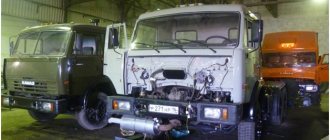
Meet UAZ 452
The car was a cargo-passenger version of an off-road vehicle with a 4x4 wheel arrangement. The Ulyanovsk Automobile Plant mastered production of the model back in 1965.
You can evaluate its capabilities by watching the following video:
The UAZ 452 is capable of transporting cargo weighing up to 700 kg in the back. In addition, it can tow a trailer weighing 850 kg. The vehicle became very popular not only in Russian off-road conditions, but was also successfully used in large cities in various capacities (pictured in the article).
In particular:
- Like a traffic police car;
- As a fire engine;
- Ambulance car;
- Grocery store;
- Utility vehicle, etc.
The famous Barefoot on the basis of UAZ 452 - a road train in the Izmailovo Central Park of Culture and Culture
Electronic components
The electrical wiring of the UAZ 452 was a simple single-wire circuit.
Structurally, it had the following solutions:
- The role of the second wire was played by the metal body and the components and assemblies attached to it;
- All electronic components and actuators had a “-” displayed on the housing. The cost of such a solution justified the imperfection of the scheme.
For reference: The instructions provided for regular checking of contacts. When oxidized, they should have been cleaned with sandpaper.
Power unit
The engine compartment is located directly inside the car, as this is due to its design.
Access to components and assemblies is also provided from the passenger compartment by removing the cover, which:
- Provided protection for the driver and passengers from the penetration of exhaust gases;
- Protected from dust and dirt;
- Served as an additional heating element (passive - from heating).
The high engine layout contributes to the vehicle's cross-country ability in off-road conditions
The previously used engine from Pobeda was replaced with a more modern engine from the 21st Volga. This was facilitated by the launch of a production line at the Zavolzhsky Motor Plant in 1964.
Passive vehicle safety
The design of the "Baton" with a cabover layout also initially raised a number of questions regarding safety. However, a series of crash tests conducted back in 1971 at the Dmitrov test site proved that in most emergency situations the driver and passengers of the UAZ 452 have a chance to avoid injury. A striking example of comprehensive testing of “Tablets”
Individuality of electrical equipment
So, what are the features of the UAZ 452 wiring diagram? At the time of the start of production, the more difficult part for the company’s engineers and designers was finding the highest quality parts and devices.
Namely, we are talking about parts for the vehicle lighting system, as well as ignition, which can be especially clearly seen by how the car’s cabin is filled:
- governing bodies of various transport systems;
- control devices for monitoring the status of components and devices.
Outdoor optics
At that time, designers had to resort to almost all freelance solutions in order to mass-produce cars.
- The UAZ electrical circuit contains an optics switch, which was borrowed from the GAZ 69. By the way, the latter is the predecessor of the Bukhanka.
- In addition, virtually all the optics were borrowed from the GAZ 64 - these are lights, etc.
Ignition system
Improving the electrical circuit of UAZ 452
The first copies of the UAZ 452 saw the world in 1965 and forever entered the history of Soviet automobile production. The electrical circuit of the UAZ 452 and even the body structure of this car are trouble-free.
The car has become a truly multi-purpose means of transportation. It was used for both military and medical purposes.
It is especially worth noting the reliable electrical equipment of the UAZ. Over the years of production, the car has undergone many changes. For example, the UAZ wiring diagram has become much more modern and technologically advanced.
Release 1965 - 1984
If we talk about the beginning of production, then that UAZ 452 electrical equipment circuit lasted on the assembly line until 1984. During this period, many details in the circuit were borrowed from other models. Also, quite a large number of details could be called experimental. However, as the future has shown, such simplicity resulted in extreme reliability during operation.
In those years, it was quite a difficult task to find the necessary elements and parts. This problem was especially pressing in ignition and lighting systems. Therefore, the solution was to borrow parts from predecessors. So, a foot light switch was taken from GAZ 69.
She got the Bukhanka's headlights from the GAZ 24. The ignition system was copied with minor changes from the Volga. Therefore, it is not surprising that the GAZ 452 manufacturers also borrowed the engine from the Volga. As for the electrical circuit, everything was very primitive and simple, but at the same time practical and reliable. In addition, the price of the issue clearly justified such simplicity.
New modifications
Since 1985 the car has undergone changes. They can even be called quite significant. It is also worth considering that in recent years the electrical circuit of the UAZ 452 has been quite seriously modernized.
And the basic equipment itself has become noticeably richer. Now the injector has become a modification for the UAZ Bukhanka. The manufacturer abandoned carburetor systems and released a more economical and modern injector for the UAZ Bukhanka.
The electrical equipment of the UAZ has become more progressive.
The dashboard has also been transformed. The most noticeable changes were: an additional starter relay, additional resistance in the battery ignition circuit. However, most Bukhanka owners upgrade their vehicle themselves. And the dashboard is the first step to modernizing the interior.
This overlay is freely available, and buying it is not particularly difficult. The dashboard in the UAZ 452 is all-metal and does not decorate the interior.
Modern panel trim is mostly made of plastic and serves as a good decoration for this car.
Another drawback in the old Loaf is the lack of electric windows. However, power windows can be easily installed yourself. They will fit perfectly into the electrical circuit of the UAZ 452. But neither the installation of window regulators nor their initial absence in the electrical wiring is the main problem of the poor configuration.
Improvement of electrical equipment
Most car enthusiasts will agree that an equally important thing is the central locking on the UAZ. The lock for the UAZ Bukhanka can be easily purchased at any auto parts store and installed on the vehicle without any problems.
Another “upgrade” for this car is an electric engine fan. An electric fan is a standard part for most modern cars. However, in older models such a device was not installed.
Many car enthusiasts have already become convinced of the usefulness of such a wiring part as an electric fan, so it is often installed on the Bukhanka, especially since it can be easily purchased at any car store.
Injector, dashboard, electric fan, heated mirrors - after so many innovations, the UAZ wiring diagram is undergoing changes. And for the smooth operation of all the above improvements, a good generator will not hurt. The standard UAZ 452 generator cannot be called bad, however, according to statistics, most owners still decide to install another generator.
To do this, you can take a generator from any other brand of car. For example, generators from Volkswagen, Nissan and other cars are often installed on Bukhanka. A generator is an important element of electrical wiring, so if you decide to seriously improve the electrical equipment of the UAZ 452, then a new generator may be needed.
Post tags:
Finding defects
All Russian cars sometimes experience difficulties in the operation of electrical equipment. If you see that the UAZ wiring is not working correctly, you need to diagnose it and check all parts. If there are any defects in the operation of electrical devices, you must first check whether the fuses in the mounting block have blown. If everything is fine with these elements, but the equipment still does not work, for example, if we talk about optics, then you need to check whether the light bulbs are working. If the lamps themselves are working, you need to test the electronic part using a tester (the creator of the video about testing car wiring is Ramil Abdullin).
If the Loaf completely refuses to start, you need to create the following:
- First, check the functionality of the battery.
- With the battery charged, use a tester to test the circuit from the coil to the generator; often the reason for the impossibility of starting the engine is breaks in the wiring. If there are breaks, the wires should be changed. If there is oxidation on the contacts, they should be cleaned.
- Starting the unit will be impossible in the absence of a spark. To diagnose the presence of a spark, remove the high-voltage cable from the spark plug and bring it to the body. When you try to start the engine, a spark must jump between the cable and the body.
- If there is no spark, perhaps the problem lies in the presence of soot and deposits on it. By the way, carbon deposits are often a prerequisite for unstable engine operation and tripping. To get rid of such a malfunction, it is better to clean the spark plugs; step-by-step instructions for this process are presented here.
UAZ-390945 Farmer
We are used to the fact that the UAZ Patriot is regularly improved: the technical components are improved, the design is improved. All these innovations are heard and visible. And around the Ulyanovsk “old guys” - cabovers (more than 60 years on the market!) the information background is not so dense. Many people are not aware that these cars have also changed significantly in recent years: they have acquired power steering, front disc brakes, and a five-speed manual transmission. Passenger “loaves” are required to be equipped with ABS.
And at the beginning of this year, the cabover family was again modernized. To evaluate the updated UAZ-390945, I went to Ulyanovsk.
Evolution of a classic
While I was flying on the plane, I studied the changes made. The list, frankly speaking, is small.
“This is really not a radical modernization,” UAZ chief engineer Evgeniy Galkin anticipated my question. “Our cabovers are the most affordable all-wheel drive commercial vehicles on the market, and they are valued for that. Here are the sales data last year: everyone dipped except us! If the model is radically updated, the price will increase significantly - and we will lose our main competitive advantage. Therefore, we decided to improve the car point by point. The main complaint from buyers was the weak frame: cracks in it were not uncommon, especially in the places where the power steering and body supports were attached. We introduced additional reinforcement in these areas, increased the thickness of the cross member, and the complaints should come to naught. In addition, the frame and body are now separated not by an ephemeral gasket, but by a soft cushion that effectively absorbs vibrations - the easiest way to identify the 2016 “tadpole” is by it.
Video
Overhaul of UAZ wiring from the author Ivan Saichenko.
UAZ 2206 Bukhanka is the popular name for a family of all-wheel drive cargo and passenger off-road vehicles produced in various modifications since 1965 (UAZ 452, 3741, 3909, 39094, 3962, 3303, 3741) mainly with gasoline engines (injector and carburetor). In this article we will show an electrical diagram, a description of the fuses and relays of the UAZ Bukhanka 2206 and their locations.