The GAZ 3307 truck is the workhorse of many entrepreneurs today. It is chosen by those who can’t get enough of a regular Gazelle, and who need a larger and more spacious car. The car is also highly reliable and off-road. The frame design provides a load capacity of up to 4.5 tons. Despite the arrangement of the drive wheels 4x2 and the fact that the car is intended for use on paved roads, it can still move off it.
Moving some very dirty areas somewhere in remote villages can also be carried out quite successfully. In general, the car was created in our country and exclusively for our conditions.
As for the engine, the V-shaped “eight” with a power of 125 horsepower may well be enough for the car and the driver to feel comfortable even with a fully loaded body. In addition, starting from this model, a diesel engine is installed on the car. This was the first departure from the gasoline and in-line V-shaped “six”, which were consistently installed on previous cars. Unlike them, the diesel engine here has been completely redesigned and is a completely economical model. We devoted some time to the external differences of this truck from others, but now let’s move on to our main topic, and today we are interested in the brake system GAZ 3309.
Brake system GAZ-53
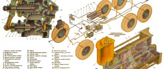
The brake system of the GAZ 53 is hydraulic; it consists of 3 mechanisms: service, spare and parking brakes. In fact, there is only one hydraulic system, but divided into circuits, each of which is conditionally considered a spare one. It is also interesting that the brake system of the GAZ 53 has an indicator on the dashboard. That is, in the event of a drop in pressure inside the hydraulics, a red lamp will inform the driver about this.
Gas 53 brake system diagram
General device
When this truck was being designed, and, by the way, it was created almost from scratch, so as not to depend on previous models, it was decided to make a completely new, unique braking system. It includes the following types:
- Working.
- Parking lot.
- Spare.
All of them have the same purpose to reduce the speed and/or stop the car when the driver of the car wants it. In addition, it is worth considering that for a truck, the brakes must be more powerful, so that in an emergency you can always stop it and avoid a traffic accident. The working system is the main one because it is constantly used when the machine is moving.
Its main control is the foot pedal, which is located between the clutch pedal and the gas pedal of this car. It is worth noting that on previous GAZ 53s the pedal was pressed very tightly, but here it is exactly the opposite, very softly and smoothly, almost like on foreign cars. The parking and spare systems are one and the same in this car. They accordingly have fewer devices required for their operation, and they can be used at any time. The parking brake is necessary to hold the car motionless during long stops or when it is necessary to move away downhill.
Even experienced drivers often use it, since a fully loaded car is difficult to catch and move without rolling back on a sufficient slope.
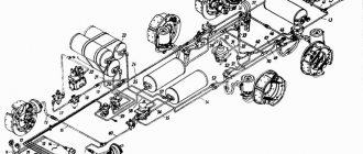
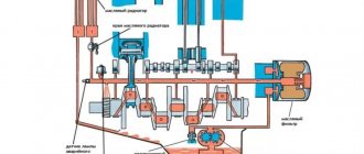
Diagram of the brake system GAZ-3309 (diesel) with an air dryer
The diagram itself is shown in the photo below.
- Compressor installation.
- GC reservoir.
- Emergency sensor.
- Filter.
- Rear wheel braking design.
- Sensor.
- Pneumatic signal switch.
- Muffler.
- Drain tap.
- Braking device for front wheels.
- Critical pressure indicator.
- Air reservoir.
- Check valve.
- Safety single valve.
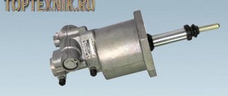
- Pneumatic booster.
- Modulator.
- Control valve.
- Atmospheric balloon.
- Air dryer.
- Piston sensor.
- Brake valve with two sections.
Features of brakes of GAZ 3307 cars
GAZ 3307 trucks are equipped with a brake drive with a system that notifies about breakdowns. Separate axle braking is provided. The circuits are equipped with a hydraulic vacuum type amplifier and a vacuum cylinder with a shut-off valve.
With the help of vacuum cylinders, autonomous power supply of each existing circuit is guaranteed. Special sensors with alarms provide control over the vacuum level. If the warning light starts to light up, this directly indicates a low vacuum level in a particular circuit.
The hydraulic drive of the brake mechanisms on the wheels located at the rear of the truck is equipped with a brake pressure regulator.
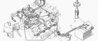
Vacuum pump features
An important design element is a vacuum amplifier, which is capable of creating the necessary pressure in the system. Due to this, it is possible to significantly increase braking efficiency, as well as reduce the required force when pressing the pedal. It should be remembered that incorrect operation of this important unit is a dangerous breakdown, leading to unstable operation of the power unit.
This is due to the entry of air into the intake pipe of the engine, which contributes to the leanness of the fuel mixture in its cylinders. As a result, the car cannot operate for a long time and periodically stalls. The design of the system involves the removal of lubricant and mechanical damage to the cylinders in the event of such a malfunction, which is why it is necessary to eliminate it as soon as possible.
Basic structure of a specific system
Any braking system can be divided into two components:
- Driven.
- Mechanical.
The mechanism ensures the creation of a moment of resistance to movement, and the drive is needed in order to activate the mechanism at the time required by the driver.
Mechanisms
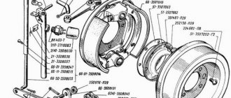
The mechanism includes various friction parts that are installed in direct contact with the wheel. The parking mechanism here does not contact the standard brakes; it has its own separate mechanism. It is installed on the driveshaft and locks it when turned on. Drum-type brake mechanisms are installed here, as they are optimal for such a truck. The rotating part here is the drum itself, and the stationary part is special belts or pads that are pressed against it.
The drum body is tightly connected to the wheel and rotates with it. Inside it, there are brake pads on springs, which, when you press the pedal, are pressed against the drum and slow down its rotation. The drums are fastened to the machine hub using a bolted connection, making the fastening as secure as possible. The pads are made of a special friction material that takes a very long time to wear out.
Drive unit
The drive is necessary in order to control the mechanism and perform certain actions with it. The GAZ 3309 is equipped with mechanical and hydraulic operating drives for the parking and service brake systems, respectively. The hydraulic drive was chosen because it is the most optimal for a simple truck.
In addition to it, there are also pneumatic and electric drives, but they have a very narrow specialization and are not installed on machines of this type.
This vehicle is also equipped with a brake warning system and a hydraulic vacuum booster with a vacuum cylinder and a shut-off valve. Here, separate hydraulic circuits are installed on each axle of the vehicle. That is, if one fails, the second will still perform its functions and will be able to ensure that the machine stops without an accident. The cylinders provide power to each circuit separately, this is also for safety reasons. Along the path of the circuit, they have a built-in brake pressure regulator, which is necessary to provide the required force when one of the circuits fails and to regulate equal force on each wheel. That is, to put it simply, it makes sure that the remaining circuit does not receive twice as much effort due to the fact that the second one does not work. In this case, the working stroke of the pedal increases slightly and braking may occur when the driver of the GAZ 3307 lowers the pedal to the floor.
Under the hood, the main brake cylinder has found its place, which senses pedal pressure and, through small pistons, creates the necessary pressure in the circuit. The brake cylinder is also divided into two chambers for each separate circuit. The main brake pistons are equipped with special floating heads, which are essentially a variation of the bypass valve. When the pedal is released, the valve clearance is in the working position, that is, the main brake is connected to the expansion tank. When the driver presses the pedal, the pistons move and the heads, under the action of springs, are pressed into the pistons and close tightly. Thus, the communication between the cylinder and the tank is interrupted and the first pressure is created in the system. The entire system is powered from the expansion tank. During normal daily operation of the brakes of a GAZ 3307, the brake fluid level should be close to the maximum. With new brake pads and the sensor removed, it should be at the maximum mark.
The sensor signals a sharp drop in the brake fluid level, which in itself indicates a leak in the system and a violation of its tightness. This is unacceptable for a truck, so before leaving it on the line, you should check the functionality of the brakes and the fluid level in the expansion tank.
A brake booster is necessary to create additional pressure in the system circuits. This improves the braking quality of the car, and the driver does not need to press the pedal with all his might. The principle of operation of the special hydraulic vacuum brake booster on the GAZ 3307 car comes down to creating an additional engine in the intake system and thereby creating additional pressure. When it comes out, the quality of braking can sharply deteriorate, since there is a constant leak of air into the intake pipe of the engine. This can deplete the fuel mixture in some of the engine cylinders, as a result of which the car may stall and will not start again until the problem is corrected. In addition, the unburnt mixture can wash away the lubricant in the cylinders and the piston will scratch the cylinder bore, which can even lead to engine failure.
Steering repair
Steering malfunctions also affect traffic safety, as do brake system malfunctions, and operating a vehicle with such defects is prohibited. Problems must be corrected immediately after they are discovered. Malfunctions of the model 3307 include:
- steering wheel play exceeds the permissible norm;
- knocking when turning the steering wheel;
- tight turning of the steering wheel;
- oil leak from the steering mechanism (gearbox).
Steering mechanism diagram
- play in the steering rod joints or steering tips;
- wear of the worm pair in the gearbox;
- play in the crosspieces of the steering driveshaft;
- jamming of steering joints and rods;
- play in the steering gear bearings.
Structural elements of the brake drive
The main brake cylinder builds up pressure in 2 independent hydraulic circuits using pistons. The primary cavity is responsible for the functioning of the rear brake circuit, and the secondary cavity is responsible for the front brake circuit. The pistons of the main brake cylinder are equipped with floating heads, the main task of which is to act as a bypass valve.
In the initial position, under the influence of the return springs, a gap is provided between the piston and the head. The cavities of the circuits (front/rear) are connected to the tank. The seal occurs due to rubber rings located in the piston heads. The valves are responsible for maintaining excess brake fluid pressure.
If one of the circuits breaks down, an increase in pedal travel is observed as a result of idle movement of the piston of the faulty circuit. If the circuit is in working condition, the required level of pressure is provided, which facilitates the braking process.
To replace deformed and worn parts, the vehicle unit is dismantled: the body is disconnected, the thrust bolts are unscrewed, and then the pistons are removed. Before starting assembly, all structural parts should be washed with brake fluid. It is important to prevent dirt, dust, small debris, oil and various particles from entering the assembly. When assembling the unit, the thrust bolts must fit into the grooves of the pistons.
The GAZ brake system is powered by the provided tank. When the sensor is removed and if there are new brake linings, the fluid level should be within the Max mark. If there is a decrease in the amount of fluid and the brake system as a whole is in good technical condition, then the main reason for this is the natural wear of the linings.
Activation of the liquid level drop alarm in most cases occurs due to a decrease in the tightness of the system.
Clutch repair
3307 trucks often operate at maximum loads. A fully loaded car cannot drive in one gear when going uphill, and shifting gears in this mode forces the clutch to work quite hard. In addition, the 3307 gearbox is not synchronized and requires double squeezing when changing from one gear to another. Due to the heavy load on the clutch, it often fails and has to be repaired.
Signs of poor clutch are determined by pedal pressure:
- It fails, the gears cannot be engaged;
- Doesn’t squeeze out completely and sticks up;
- The pedal is too “soft”;
- Large free movement, squeezing occurs at the very end.
Operating principle during braking
Having dealt with every nuance of this truck’s braking system, we just have to figure out how braking happens on it, what generally happens in the car after the driver presses the brake pedal.
So, when the driver presses the brake pedal, the hydraulic vacuum booster perceives this pressure and increases it many times, redirecting it to the main brake cylinder of the truck. Both pistons, if all circuits are working properly, begin to increase the fluid pressure in the circuits in proportion to the pedal press. In this case, the force value increases sharply and the working cylinders on each wheel begin to move the pads in the car drums. As you continue to move the pedal, the pressure increases even more and the operating mechanisms are fully activated. That is, the pads engage with the drums and begin to slow them down. This causes the rotation of the wheels to slow down due to the braking force generated at the point where the wheel contacts the road. The braking force counteracts the rotational force of the wheel and the car slows down.
Accordingly, the harder the driver presses the pedal, the higher the pressure in the circuits will be and the better the braking of the entire car will be.
When there is no need to brake, the driver removes his foot from the pedal and the return spring moves it to the free position. Following the pedal, the pistons in the brake cylinder also assume a free position. Also, the pads are retracted from the surface by special springs. Excess lubricant from the circuits is squeezed out into the main brake and flows through the open heads into the expansion tank. The pressure in the system drops to minimum values.
ZIL 130, ZIL 131, GAZ 3307, GAZ 3102, GAZ 3110, GAZ 53, MAZ 500, T 25, T40, Izh Planet, Izh Jupiter
GAZ 53 » Maintenance of brake systems » Adjusting the gap between the pusher and the piston of the master cylinder
When adjusting the free play of the pedals, disconnect the brake pedal 6 (Fig. 1) from the rod 4 by undoing and removing the pin connecting them. Check the position of the pedal. Under the action of the tension spring 5, the pedal should rest against a rubber buffer fixed under the inclined floor of the car cabin. Unscrew the locknut 3, screw in the rod 4 of the pedal pusher 2 of the piston of the main brake cylinder 1 so that when the piston is in the extreme forward position, the axis of the rod hole is shifted back and does not reach the axis of the pedal hole by 1.5 - 2.5 mm. Without violating this position, securely lock the connecting rod 4 and the pedals in the pusher 2 with a lock nut 3. Align the holes of the pedal and the connecting rod, insert the pin and secure it with a cotter pin.
Filling the hydraulic drive of the service brake system with fluid (bleeding). The brake system is pumped when the fluid is replaced or when air enters the hydraulic system due to the replacement of a worn part or assembly that causes depressurization of the system. The hydraulic brake system has two independent circuits, which are pumped separately when the engine is not running and there is no vacuum in the boosters. During bleeding, maintain the required level of brake fluid in the master cylinder, avoiding a “dry bottom”.
Before bleeding, unscrew the master cylinder reservoir cap and fill in Rosa, Tom or Neva brake fluid. Press the brake pedal several times to fill the cavities of the master cylinder with brake fluid. Remove the protective caps from the bleeding valves.
How to replace the main brake cylinder of GAZ 3307
Useful tips for do-it-yourself car repairs.
Recommendations from car service specialists and experienced car owners.
Useful tips on car repairs for ordinary drivers and professionals. All the necessary information about repairing and maintaining your car is available in e-books
and
regular printed publications
. Electronic manuals are convenient to use on a computer, smartphone or tablet. They will always be at your fingertips.
How to disassemble the piston of the main brake cylinder GAZ 3307.4301
Replacing the main brake with Gas 66 and bleeding the brakes
About the life of my Gas 66 (shishigi) in my hands and its adventures Subscribe ✔️ to the channel, it will be interesting...
gas 3307
Brake system GAZ 3307.
Repair of the main brake cylinder.
Restoration, repair of the brake cylinder. JOIN VSP GROUP PARTNER PROGRAM: https://youpartnerwsp.com/ru/join?92190.
Replacing the vacuum brake booster GAZ 3307, GAZ-53…
We are replacing the vacuum brake booster on a GAZ-3307 (GAZ-53). The brake pedal rose up when pressed...
How to disassemble the hydraulic vacuum booster of the brake cylinder on a GAZ 3307
Disassembly and troubleshooting of the hydraulic vacuum brake cylinder gas 3307
.
repair of the brake system, brake master cylinder and booster gas 4301
urgent repair of the gas 4301 brake system, detailed analysis of the hydropneumatic booster and main brake...
Repair of the main brake cylinder gas 52
Hello, in this video I will show you how to easily and quickly repair a car's brake master cylinder...
How to bleed the brakes and make the clutch go to gas 52?
In this video I will tell and show, together with my grandfather, how to bleed the brakes and clutch on our Gas 52 Project...
master brake cylinder
Watch the video How to replace the main brake cylinder of a GAZ 3307 with your own hands.
In this video, experienced owners share tips on how to replace the main brake cylinder of a GAZ 3307 yourself.
Video advice from experienced drivers How to replace the main brake cylinder of a GAZ 3307 based on personal experience
The video shows how to replace the main brake cylinder of a GAZ 3307 in a garage without the help of specialists.
You will find more detailed information about repairing and maintaining your car in
e-books
and
regular printed publications
.
For those who are accustomed to using regular printed publications, we recommend buying car repair manuals in the online store of the Legion-Avtodata publishing house
Automotive literature stores:
krutilvertel
— Electronic books of printing quality in PDF format
autodata
— Online store of the publishing house Legion-Avtodata