A plow is an integral tool in agriculture, which is used to plow the soil using metal moldboards and ploughshares. Often, purchasing a unit for older model tractors is useless due to the inability of hydraulic attachment systems to interact with attachment mounts. The homemade plow on the T-25 is not complex in terms of its body structure. Each farmer can make such a unit on his own.
DIY attachments for the T-25 tractor
There is a large selection of trailed attachments for the T-25 tractor, so we will not only talk about homemade plows. If the user is not able to purchase factory units, then there are several methods of self-assembly. Detailed instructions for making all types of attachments with your own hands, as well as video tutorials, will help you assemble the device correctly and reliably.
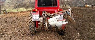
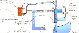
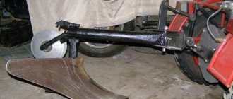
Homemade plow
The manufacture of attachments is carried out in several ways. If you do not have special rollers at hand for bending metal sheets, then use simpler manufacturing methods. The plow must withstand heavy loads, so alloy steel with a thickness of at least 3-5 mm, which is protected from corrosion, is used during assembly.
An important part of the unit is the plowshare, which must be made durable, adjustable and removable in order to be able to vary the depth and avoid damage to the structure.
The first case of assembly involves making a blade from a metal pipe with a diameter of 55-60 cm. The thickness of the steel should be at least 0.4 cm. A template for cutting out structural parts from steel is made according to the drawings from thick cardboard. Rollers for bending steel sheets will speed up the manufacturing process. The blanks are cut from cardboard exactly to size and fed onto rollers at an angle of 20°. After bending, the structural parts are easily brought to the desired shape with a hammer on an anvil.
The second method is labor-intensive and does not involve the use of rollers. The blank for the dump is heated in the forge for subsequent processing. Here it is preferable to use a ready-made blade from old equipment for the T-25. The cut templates are applied to the blade at an angle of 20°, preliminary marking is carried out with chalk on a surface sanded. Otherwise, the process repeats the first method, and a gas welding machine is used to cut out parts.
Welding work is carried out by fastening the plowshares with the blade and the metal sheet under which the shield is placed. The blades of the share must be at the correct angle, as well as the top edge. To connect the parts of the plow structure together, welding is also performed. In order for the plow to hold the furrow, its design includes a wheel unit, the height and angle of which are varied by a bushing with a notch. The diameter of the wheel must be at least 20 cm. This process is discussed in more detail in training videos for homemade plow making.
After assembly and minor adjustments, the plow should work properly if you have maintained the correct angle of the plowshares relative to the location of the blade.
DIY potato digger
Making a potato digger for the T-25 tractor is a less labor-intensive process than assembling a plow, but is carried out strictly according to the diagrams. The mechanism of its operation is simple: the ploughshare opens the soil, the elevator grabs the tubers, passes them along the grate, clearing them of soil, and dumps the peeled fruits.
The frame of the unit is made of metal sheets, which are best connected not by fasteners, but by welding. The elevator casing is installed on the frame and secured through holes that need to be drilled. When attaching to the frame, it is important to use bolts that will allow you to change the angle of inclination of the elevator and the plowshare with which it will be attached. The ploughshare is made of thick alloy steel and is shaped like a bucket, the corners of which must be rounded.
The manufacture of the digger drive is carried out using gears, hubs and shafts. The mechanism is quite simple; at this stage it is important to follow the assembly algorithm described in the diagram. A more complex design is the cleaning drum, consisting of two chains that are strung on steel pins and fastened with metal sheets. This mechanism is driven by a shaft. The connection to the T-25 shaft is carried out using a structure with a shaft, bearing and pin.
Homemade coon
On the T-25 tractor it is possible to install a front factory load of no more than 200 kg with a low load capacity, since the design of the tractor cannot withstand heavy loads. There are few examples of assembling a homemade kun, since experienced users note a high risk when using homemade structures, especially those with a large weight.
DIY cutter
The answer to the question of how to make a cutter yourself is simple. The body of a homemade cutter is made of steel sheets 1 cm thick and a 12 U channel. The main unit is a gearbox and a transmission connection, which can be used as a ready-made unit from a similar old device; there are options, for example, a bridge from a Zhiguli car. The side mechanism is assembled using oiled gears.
Knives for the cutter are made from durable thick metal and are cut according to a template using a gas welding machine. After sharpening on a machine and sanding, the knives are attached to the shaft. The connection to the body and PTO is carried out through a bearing mechanism and bolted fastening.
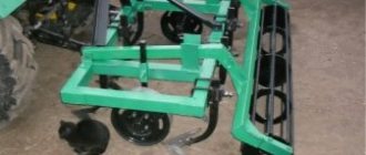
Cultivator
When making a homemade cultivator, it is important to choose materials that do not corrode, so that the moisture present in the soil does not oxidize the frame. To make a three-row frame, thick steel pipes or channels are used. Hinges are attached to the drive beam, which will allow the cultivator blades to move correctly smoothly - this will allow you to vary the depth of immersion of the blades into the ground and will not allow the mounted cultivator to get stuck in the soil.
An important point is the manufacture and fastening of sickle-shaped paws with knives that loosen the soil. They are made of stainless materials, and their elements are fastened together by welding. The floating mechanism of the knives is adjusted by a spring mechanism, for example, from an old seeder: for each knife there must be a separate spring with the required level of tension.
It is better to make the drive wheels made of metal and make them wide. This will allow them not to get stuck in the soil and act as rollers or a press that compacts loosened soil. If necessary, standard harrows are attached to the body on chains behind the cultivator's paws, which will provide additional loosening of the soil.
Shovel
There are many options and drawings for making a shovel for the T-25. Most often, for homemade attachments, cross sections of thick, large-diameter pipes are used, which have the required bend and all that remains to be done is to bring the shape of the shovel to the desired size and assemble a simple attachment mechanism.
To make a shovel, a steel sheet can be given the desired shape by heating or using rollers. Material with an anti-corrosion coating is taken so that the attachments last longer.
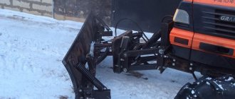
Mounted loader
Unlike the front suspension, homemade rear suspension structures for the T-25 are common. Some design options can be complex, so during manufacturing it is necessary to clearly focus on the rear loader assembly diagrams. The ladle can have various shapes, but must be made of thick steel. This will help avoid premature deformation of the fastening elements and the bucket itself during operation. The main difficulties during assembly arise in the manufacture of the hanging frame.
The most common type of fastening is a V-shaped inverted hydraulic frame with a movable unit at its top. Compared to other types of mounted loader, it is simple to manufacture and provides variable lifting stroke, but when lifting heavy loads, the user may have problems due to the large travel radius of the bucket. For manufacturing, thick steel blanks and channels are used that can withstand sufficient load. The elements are fastened with strong welding.
To control the stroke of a homemade loader bucket, factory retractable hydraulic cylinders of appropriate power are most often used, which are connected to the tractor’s hydraulic linkage system via oil hoses.
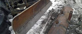
Do-it-yourself blade
The shape of the blade located at the front, as well as the rear shovel, can be different. The principle of making the shovel itself is simple, but the main attention should be paid to the correct fastening and supports that can withstand the load and not break the tractor frame.
Hydraulic control of the blade is provided by a factory extendable cylinder, which can be borrowed from almost any old attachment. It is mounted in the front of the tractor. To do this, metal plates with a through hole are welded to the front frame beam, and a cylinder socket is attached between them. The same plates act as fastenings on the blade itself.
2 support beams are mounted at the bottom of the blade and in the middle of the tractor frame. To do this, thick plates located perpendicularly are welded to the frame. Through through holes, support beams are attached to pulleys and do not allow the blade to move freely, controlling its progress.
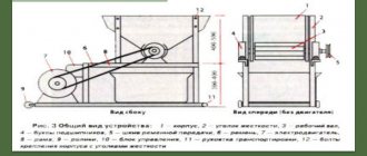
Rotary cutter
The rotary tiller has a complex design, so it is convenient to take the gearbox from the popular PK-1.6 stacker as a basis. The side mechanism is easier to assemble and is made from parts of passenger cars. The gearbox with the transmission mechanism should be mounted on a square frame welded from thick channels, and in the lower part there should be a shaft with knives, for the manufacture of which springs from KAMAZ are suitable. Knives must be sharpened on a machine to achieve a good loosening effect.
Ladle
The bucket is a universal tool that is easy to assemble and fasten. There are several drawings for making buckets of different shapes. For manufacturing it is necessary to use thick steel that is resistant to deformation.
How to make a hiller
For manufacturing you will need a channel and a small supply of thick steel. According to the drawing, a V-shaped structure, shaped like a double plowshare, is attached or welded to the sickle-shaped share. At the point where the hiller blades converge, a baking powder is additionally installed.
Bulldozer
The principle of mounting a bulldozer on the front of a tractor is similar to mounting a blade. Remember that if you are going to make a large working part of a bulldozer, you must increase the strength of the support beams and use a powerful hydraulic cylinder.
Potato planter
A potato planter is the most difficult unit to assemble yourself, but there are many video tutorials and drawing options that will help you understand the complex manufacturing process.
Design of the T-40 tractor - design features of the unit
Even taking into account the presence of many high-tech agricultural machinery on the modern market, it is extremely difficult to imagine a more economical and productive unit than the T-40 tractor. Today, several modifications of this tractor are actively used in the agricultural sector: T-40 and T-40M are equipped with rear-wheel drive, and models T-40A, T-40AN, T-40ANM, T-40AM and T-40AP are equipped with all-wheel drive.
All of the above modifications have almost identical designs. The tractor motor is located on a semi-frame, to which the gearbox is rigidly attached. Elastic gaskets are provided between the engine crankcase and the semi-frame to dampen vibration from the engine.
The design of each T-40 unit includes a modernized fuel system, which is distinguished by the presence of a high-quality fuel supply pump and an enlarged carburetor, the internal walls of which are coated with a special chrome plating. Another advantage of the fuel system of the T-40 tractor is its simple design, which allows you to quickly and efficiently repair the unit.
The gearbox is equipped with shafts placed in a transverse position. Behind the clutch there is a bevel gearbox. The clutch itself has a dual design, with its main part connected to the power take-off clutch. At the rear of the T-40 tractor coupling there is a control unit for the side and rear shafts, as well as a drive mechanism.
The movement of the steering column of the unit is transmitted to the power steering via a cardan shaft. This ensures more precise control and instant response of the unit to driver commands. The generator of the T-40 tractor has the design of a contactless three-phase electric machine with one-way electromagnetic excitation. Its design includes built-in rectifiers, voltage regulation and high-quality aluminum wiring.
T-40 tractor engine
The review of the T-40 tractor should begin with its “heart”, namely the engine. Various versions of factory engines were installed on tractors of the T-40 family. Thus, models equipped with D-37 engines are distinguished by rounded hood shapes, while units equipped with a D-144 engine have rectangular hoods.
All engines used to equip the T-40 tractors belong to the class of diesel 4-cylinder internal combustion engines with a cylinder diameter of 10.5 cm and a piston stroke of 12 cm. For starting, each engine is equipped with a PD8 starting gasoline engine and an electric starter.
Each of the engines presented for configuration is distinguished by modest fuel consumption, endurance and high engine life. Without a doubt, this was one of the reasons why the good old “magpie” is still in high demand among farmers.
Agricultural machine transmission
The T-40 tractor gearbox belongs to the class of 4-way reversible mechanisms equipped with a blocker. The transmission differential consists of two satellites and has a closed design.
Spur gears are responsible for switching the main gear. The central gear is engaged by means of bevel spiral gears.
Hydraulic system of the T-40 tractor
The manufacturer has included in the design a high-quality hydromechanical amplifier and a three-spool 4-position hydraulic distributor, which are located on the rear wall of the battery block.
The height of the main cylinder is 9 cm, and the piston stroke is 20 cm. To pump oil, the hydraulic system design provides a gear pump installed in front of the engine of the T-40 tractor. The oil fill tank is attached to the hydraulic booster bracket.
The mechanism for installing attachments is located at the rear of the transmission unit. Mounting of attachments is carried out using a three-point design. For continuous oil circulation, connecting hoses are installed in the hydraulic system design.
Unit wheels
The rear axle of the T-40 tractor with larger wheels is equipped with a rigid suspension, while the front axle with smaller wheels is equipped with a spring-type suspension. All 4 wheels are equipped with high quality tires with a herringbone tread pattern.
For certain purposes, the tractor can be modernized by replacing wheels. For this purpose, rear wheels with a smaller width can be mounted on the unit. It is also possible to install dual wheels on the T-40 tractor. For safer movement on steep slopes, the tractor can be equipped with “inside out” wheels with an asymmetrical disc plane
Cabin and interior
The T-40 tractors are equipped with single-seat closed cabins made of durable stamped panels. The panels are connected to each other by spot welding, and all joints are treated with a special sealant. Each factory cab for the T-40 tractor has increased safety due to the presence of a special tubular frame in its design.
The advantages of the tractor cabin include a large viewing radius. The walls of the structure are 90% glass. To clean the surface from dirt and water, windshield wipers are provided on the windshield.
Homemade hitch
To make a simple rear hitch, you will need channels 10 cm thick, connecting beams and coupling devices from any small tractor. Holes are cut in the channels to allow them to be attached to the tractor frame. After this, the crossbars are pulled together by coupling devices crosswise and hung on the connecting beam. It is necessary to cut holes at the opposite end of the channels. They will allow you to attach a trailer or hitch for attachments to the hitch.
Advantages and disadvantages of the T-40 tractor
Like any other tractors, the T-40 agricultural unit has its pros and cons.
The main advantages of an agricultural machine include:
- the highest stability and maneuverability, regardless of the type of soil;
- high maneuverability at any speed;
- free access to functionality located in the rear of the tractor;
- ease of operation;
- versatility, which consists in the ability to use any type of attachments to work with the unit;
- durability and high reliability of the tractor;
- spare parts and replacement mechanisms can be found in almost any store or market;
- presence of hydraulic power steering.
The T-40 tractor has an order of magnitude fewer disadvantages. Among them, experts highlight:
- poorly thought out cooling system of the tractor engine - because of this, the engine heats up very quickly in hot weather. Do-it-yourself modernization of the unit will help correct this factory defect;
- poor engine starting in cold weather;
- The driver's cabin does not have heating or air conditioning, which has a negative impact on comfort when working in cold and hot weather.
Despite the presence of a certain number of shortcomings, the T-40 tractor is one of the most popular units in the countries of the post-Soviet space. Reviews from tractor owners indicate its high performance, regardless of the type of work it performs.
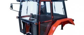
DIY cabin
For the manufacture of the cabin frame, the best material is a profile pipe to which the glass seal is attached. The dimensions of the glass pattern are determined by the size of the cabin and the thickness of the seal. It is best to use chipboard sheets as a template, which will allow you to most accurately select the desired size.
To fix the seals, thin steel strips are used, which are welded to the supporting pillars of the cabin frame. The cabin structure is welded separately, in parts, and then assembled into a single structure. Corner beams must be made of durable material that is not subject to deformation when shaking. After the cabin body is welded, you can begin cutting out the glass and glazing itself. To install the stove, it is necessary to additionally insulate and seal the tractor cabin.
Stove for tractor
Air heating in the T-25 cabin is done by many amateurs. The main heating element will be a cooling fan, from which a tube is passed into the cabin, which will pump warm air. It is important to insulate the tube with sealant at both ends so that the efficiency of the homemade stove increases. This will prevent exhaust gases from entering the cabin. The on and off function can be adjusted by installing the damper from the stove of any passenger car.
Tractor T-40 - technical characteristics
Not the least role in the huge demand for T-40 tractors was played by their excellent technical characteristics.
These include:
- power – 40 l. With.;
- working cylinder volume – 4.15 l;
- fuel consumption at maximum loads – 248 g/kWh;
- number of speeds – 7 forward/7 reverse;
- ground clearance – 50 cm:
- weight including cabin - 2.36 tons.
The dimensions of the tractor are quite modest: the length of the unit is 3.66, the width is 1.62, and the height is 2.17 m. The small dimensions allow the tractor to be actively used in small areas.
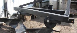
DIY trailer
The single-axle cart design for the T-25 tractor is the most suitable option. The average weight of the standard design is 800 kg, which will allow it to transport loads up to 2 tons. The cart frame is made by welding spars at least 10 cm thick. A complete axle of a small tractor can be used as an axle and wheels for the cart.
To equip the trailer with a blade option, it is necessary to reinforce the frame with a beam in the middle part. A socket is welded to the beam for installing a cylinder, which will be responsible for the dump of the body, and a reinforced support for installation. The hydraulic cylinder most suitable for a small-sized cart blade is PTS-9. The maximum output of the cylinder is 85 centimeters, which will allow the body platform to become at an angle of 50 °.
Not available:
| № | Part code | Name | Part Information |
| 25F-35-001-02 | Trailed device | Quantity 1 926741 Note Included in the assembly kit | Not available |
| 25F-35-013 | Trailed pendulum device | Quantity 1 926716 Note Included in the assembly kit | Not available |
| 25F-35-014 | Frame | Quantity 1 926717 Note Included in the assembly kit | Not available |
| [Bolt-M6-6gх16-88-019-GOST7796-70] | Bolt M6-6gх16.88.019 GOST7796-70 | Quantity 10 926718 Note Included in assembly kit | Not available |
| 25F-35-122 | Pendulum | Quantity 1 926719 Note Included in the assembly kit | Not available |
| 25F-35-123 | Axis | Quantity 2 926720 Note Included in assembly kit | Not available |
| 25F-35-124 | Plate | Quantity 2 926721 Note Included in assembly kit | Not available |
| 25F-35-125 | Stretching | Quantity 2 926722 Note Included in assembly kit | Not available |
| 25F-35-127 | Kingpin | Quantity 2 926723 Note Included in assembly kit | Not available |
| 25F-35-128 | Overlay | Quantity 1 926724 Note Included in assembly kit | Not available |
| 25F-35-130 | bracket | Quantity 1 926725 Note Included in assembly kit | Not available |
| 25F-35-130-01 | bracket | Quantity 1 926726 Note Included in assembly kit | Not available |
| 25F-56-126 | Finger | Quantity 2 926727 Note Included in assembly kit | Not available |
| 54-40-440 | Finger | Quantity 1 926728 Note Included in assembly kit | Not available |
| 150-34-106-1 | Washer | Quantity 4 926729 Note Included in assembly kit | Not available |
| 151-58-121 | Cotter pin | Quantity 4 926730 Note Included in assembly kit | Not available |
| [Bolt-M6-6gх16-88-019-GOST7796-70] | Bolt M6-6gх16.88.019 GOST7796-70 | Quantity 8 926731 Note Included in assembly kit | Not available |
| [Bolt-M6-6gх16-88-019-GOST7796-70] | Bolt M6-6gх16.88.019 GOST7796-70 | Quantity 2 926732 Note Included in assembly kit | Not available |
| [Bolt-М12-6gх45-88-019-GOST7796-70] | Bolt М12-6gх45.88.019 GOST7796-70 | Quantity 8 926733 Note Included in assembly kit | Not available |
| [Bolt-М16-6gх40-88-019-GOST7796-70] | Bolt М16-6gх40.88.019 GOST7796-70 | Quantity 6 926734 Note Included in assembly kit | Not available |
| [Bolt-М16-6gх55-88-019-GOST7796-70] | Bolt М16-6gх55.88.019 GOST7796-70 | Quantity 8 926735 Note Included in assembly kit | Not available |
| [Bolt-М16-6gх60-88-019-GOST7796-70] | Bolt М16-6gх60.88.019 GOST7796-70 | Quantity 2 926736 Note Included in assembly kit | Not available |
| [Washer-6-65G-05-GOST6402-70] | Washer 6.65G.05 GOST6402-70 | Quantity 2 926737 Note Included in the assembly kit | Not available |
| [Washer-12-65G-05-GOST6402-70] | Washer 12.65G.05 GOST6402-70 | Quantity 8 926738 Note Included in assembly kit | Not available |
| [Washer-16-65G-05-GOST6402-70] | Washer 16.65G.05 GOST6402-70 | Quantity 8 926739 Note Included in assembly kit | Not available |
| [Washer-16-65G-05-GOST6402-70] | Washer 16.65G.05 GOST6402-70 | Quantity 2 926740 Note Included in assembly kit | Not available |