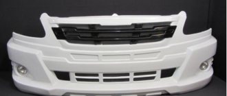
Reliable, comfortable vehicles of the GAZelle family are designed to operate on roads with improved surfaces (all-wheel drive vehicles and buses - on roads of all technical categories) in various climatic conditions. The new gazelle attracts a number of innovations, even in appearance. The bumper and radiator grille have been updated. However, the main changes are inside the car. GAZelle-Business received ten new main components and assemblies - including steering, brakes, shock absorbers, clutch, cardan, engine mounts, synchronizers, bearings. The gearbox, wheel suspensions, rear axle and front axle were modernized. The corrosion resistance of the frame, chassis, body, doors and gas tank has been increased. A high-capacity battery is installed.
The new product differs from the standard version in a large number of foreign components. The German company ZF made the power steering, the shock absorbers and clutch were supplied by Sachs, and the brakes were supplied by Bosch. Engine mounts, cardan shafts, bearings, synchronizers and a number of other parts are supplied to the Nizhny Novgorod conveyor by foreign companies. This made it possible to improve the quality and reliability of GAZelle, increase comfort and reduce the cost of ownership.
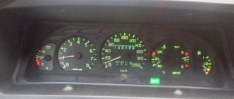
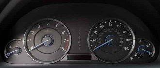
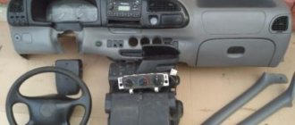
The driver's seat has become significantly more comfortable. The steering wheel is made of a material that is pleasant to the touch, and there are useful audio system control buttons on it. A new instrument panel with markings up to 200 km/h .
Audio system control buttons are installed on the steering wheel. Steering column switches, windshield wipers and a heating system appeared. The heating system is controlled using an electronic unit with a liquid crystal display. The cabin has three glove compartments and three cup holders, and the mirrors are now heated. For ease of control, the effort on the pedals and steering wheel has been reduced. The braking distance of the new gazelle was reduced by 8%. New gazelle cabin with significantly improved ergonomics. The car warranty has been increased to 2 years or 80 thousand km. The service interval has increased to 15 thousand km. Below are the main controls and controls. Many of them are compatible with previous gazelle models.
Controls of the Gazelle car:
1 — central light switch. The switch has three fixed positions: 0 - all external lighting is turned off; 1 — side lights, lighting of the instrument cluster, rear license plate and some electrical equipment controls are on; II — low or high beam are additionally switched on, depending on the position (3 or 4, respectively) of the steering column switch for the turn indicators and headlights.
2 - side ventilation grilles. 3 —device dimmer. When the outdoor lighting is turned on, turn the knob up or down and hold it in this position to select the brightness of the instrument lighting. 4 — handwheel of the headlight range control unit, depending on the vehicle load.
5 — lever for switching direction indicators, headlights and horn1). The direction indicators only work when the ignition is on. To turn on the turn indicators: right - lever up, left - lever down.
Lever positions: 1. Position for short-term activation of the direction indicators. Move the lever up or down by the amount of its own free play (until you feel a slight elastic resistance of the lever). The alarm will work as long as you hold the lever. In this case, the corresponding indicator on the instrument cluster should flash. 2. Fixed positions of direction indicators. Upon completion of the rotation, the lever will automatically return to its original position. Flashing of the indicator on the instrument cluster with double frequency indicates a malfunction of the turn signal lamp. 3. Low beam. The middle fixed position of the lever if the handle of the central light switch is in position II. 4. High beam. Move the lever forward to the fixed position.
5. Short-term signaling with high beam headlights. 11pull the lever towards the steering wheel. When released, the lever will return to the middle position. (i. Turning on the sound signal. When you press the lever button (from any of its positions) along the axis, the sound signal turns on.
6 — horn switch trim 7 — hazard warning switch. The hazard warning switch is located on the steering column housing, at the top. When the position is on, all four turn signal lamps and the indicator light (red) inside the switch button light up simultaneously in flashing mode. The hazard warning lights must be turned on when a car is forced to stop on the roadway in order to notify drivers of other vehicles and inform technical services about the presence of a stationary car on the road. The hazard warning lights work with the ignition on and off.
8 - ignition, starter and anti-theft switch. Switch positions: 0 - everything is turned off, the key cannot be removed, the anti-theft device is not turned on; 1 — ignition is on, the key cannot be removed; II - the ignition and starter are turned on, the key cannot be removed; III — the ignition is turned off, the anti-theft device is turned on when the key is removed.
To turn off the anti-theft device, insert the key into the ignition switch and, slightly rocking the steering wheel left and right, turn the key to position 0.
9 - switch lever, windshield wiper and washer
The windshield wiper and washer operate only when the ignition is on. In frosty weather, before turning on the windshield wipers, make sure that the blades are not frozen to the windshield. Lever positions: 1. Cleaning the windshield with full stroke of the brushes. Move the lever up only by the amount of its free movement (until you feel a slight elastic resistance of the lever). The windshield wiper will operate as long as you hold the lever. It is recommended to use it in light rain or when the windshield is splashed by an oncoming car. 2. Low wiper speed. 3. High speed wiper. 4. Intermittent wiper operation. The windshield wiper blades make one full stroke in the interval from 2s to 12s, depending on the position of the pause control. 5. Turn on the windshield washer. It is activated by moving the lever forward, along the steering column from any position, the position is not fixed.
10 - central ventilation grilles. 11 — handle for regulating the performance of the auxiliary heater fan (for GAZ-2705 and mod. vehicles with two rows of seats and GAE-3221 and mod. vehicles). 12 — passenger compartment lamp switch 13 — document compartment cover lock handle. 14 - CD-MP3 receiver or plug. 15 — control panel for heating and ventilation installation. 16 — handle of the lock of the upper glove box. 17 — handle of the lock of the upper lower drawer. 18 - cup holders or plugs. 19 — socket for connecting external consumers (portable lamp plug, charger, etc.) or plug. 20 - ashtray. 21 — transfer case gear shift lever (for 4×4 vehicles). The diagram for switching on the center differential lock, shifting gears of the transfer case and gearbox is shown in Fig. 5.7. — lever for shifting gears and engaging the locking of the center differential, transfer case (for 4x4 vehicles with one transfer case control lever).
22 — lever for turning on the center differential lock of the transfer case (for 4x4 vehicles - with two transfer case control levers).
And turning on the differential lock of the transfer 1) box (1 - off, 2 - on); B - gear shift of transfer case 0 (1 - low gear, 2 - high gear); C 2) - shifting gears and engaging the differential lock and transfer case (1 - low gear, 2 - high gear, 3 - low gear and differential lock engaged); D - gear changes in the gearbox
23 - parking brake lever. To brake the car, you need to pull the lever up; In this case, if the ignition is turned on, the indicator light on the instrument cluster lights up intermittently. To return the lever to its original position, you must press the button at the end of the lever handle; When the brakes are released, the indicator goes out.
24 - gear lever. The gearbox has a fuse to prevent accidental engagement of reverse gear when disengaging 5th gear. Engage reverse gear after stopping the car. When reverse gear is engaged, the reverse light comes on in the rear lights.
25 — accelerator pedal. 26 — service brake pedal. 27 — handle of the steering column fixation mechanism When you move the handle toward yourself, the fixation of the steering column is loosened, after which the steering wheel can be set to a position convenient for the driver and fixed in this position by setting the handle to its original position.
28 — clutch pedal. 29 — rear fog lamp switch. The rear fog lights are turned on when you press the switch button if the low or high beam headlights are on. The rear fog lights are turned off when: — pressing the switch button again; — switching the key in the ignition switch to position “O”; — turning off the low/high beam headlights. 30 — switch for front fog lights (on some trim levels). The front fog lights turn on when you press the switch button if the side lights are on. The front fog lights are turned off when: pressing the switch button again; — switching the key in the ignition switch to position “O”; — turning off the side lights. 31 — fuse block cover. 32 — hood lock handle. To open the hood, you need to pull the handle towards you until the latch opens the lock and the hood opens slightly, and then move the handle forward again until it stops. To open the hood completely, you must remove the fuse mounted on the lower front edge of the hood by hand.
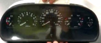
Control devices for the Gazelle car
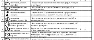
The instrument cluster is equipped with a sound signal to additionally inform the driver about critical and emergency operating modes of the main vehicle systems. 1. Fuel level indicator. 2. Speedometer. 3. Parking brake indicator. Lights up with a flashing light when the ignition is turned on, if the car is slowed down by the parking brake (duplicated by a short-term sound signal when the car is moving). 4. Low battery indicator. 5. Signal indicator for turning on the left direction indicators. 6. Emergency oil pressure indicator. Lights up when the ignition is turned on (duplicated by a short-term sound signal when the engine is running). After starting the engine, the warning light should go off. It is allowed for the indicator to light up briefly at a minimum engine speed in idle mode and during sudden braking. If the warning light comes on under normal driving conditions, you must immediately stop the engine and determine the cause of the low oil pressure. Operating the engine with insufficient oil pressure will lead to engine failure.
7. “STOP” signal indicator. Lights up simultaneously with one of the indicators 3, 6, 13, 15 and 23. When these indicators come on, further operation of the vehicle is not allowed until the malfunction is eliminated. 8. Engine control system warning light. If the control system is working properly, the indicator lights up after turning on the ignition and lights continuously for 5 - 10 seconds, then goes out. This indicates that the system is ready to start the engine. Variable lighting of the indicator while driving indicates a failure of some elements of the engine control system. 9. Right turn signal indicator. 10. Anti-lock brake system (ABS) malfunction indicator - installed on parts of cars.
11. Tachometer. Indicates the crankshaft rotation speed in min. 12. Electronic brake force control (EBD) fault indicator - for vehicles with an ABS system. 13. Door opening alarm - for GAZ-E221 and mod. (duplicated by a short-term sound signal when the car is moving). 14. Interaxle differential lock activation indicator for 4×4 vehicles.
15. Alarm indicator for abnormally high coolant temperature (duplicated by a short-term sound signal when the engine is running). When the warning light comes on, you must immediately stop the engine, determine and eliminate the cause of the drop in coolant level. Running the engine with insufficient coolant levels can lead to engine overheating and failure. 16. Coolant temperature gauge. It is allowed to operate the engine when the pointer moves to the beginning of the red zone of the scale until the alarm for abnormally high coolant temperature comes on. 17. “Mode” button. 18. Signal indicator for turning on the rear anti-human light. 19. Headlight high beam indicator. 20. Signal indicator for turning on the side light (duplicated by a short-term sound signal when the ignition is turned off). 21. Low beam headlight indicator. 22. Signal indicator for turning on the front fog lights.
23. Indicator for emergency drop in brake fluid level (duplicated by a short-term sound signal when the engine is running). Lights up when the fluid level in the master cylinder reservoir drops below the permissible level. The vehicle must be checked immediately by a service facility. 24. Indicator of total and daily mileage. The top row is the total mileage readings. Bottom row - daily mileage readings. 25. Reset button. Setting the daily mileage indicator to zero. 26. Indicator of the minimum fuel reserve in the tank (duplicated by a short-term sound signal when turned on for the first time). Lights up when the fuel level float is in the region of 8 liters. It is not allowed to drive the car for a long time after the warning light comes on, because this will lead to failure of the submersible electric fuel pump module.
| Wheel formula: | 4x2 |
| Number of seats in the cabin, persons: | 3 |
| Permitted maximum weight, kg: | 3500 |
| Weight without load, kg: | 1790 |
| Load capacity, kg: | 1710 |
| Minimum turning radius along the track axis of the front outer wheel, m: | 5,5 |
| Tires: | 175R16, 185/175R16 |
| Clutch: | Single-disc, dry, hydraulically driven. |
| Transmission | Mechanical, five-speed. |
| Main gear: | Conical, hypoid. |
| Suspension | |
| Front wheels | Dependent, leaf spring, with telescopic shock absorbers. |
| Rear wheels | Dependent, leaf spring, with telescopic shock absorbers, with or without anti-roll bar. |
| Power steering | Steering mechanism of the “screw-ball nut” type with built-in hydraulic booster. Steering column with double-joint steering shaft and compensator, with steering wheel adjustment mechanism. |
| Brake system | |
| Working | The front brakes are disc, the rear are drum. The drive is hydraulic, dual-circuit, with a vacuum booster and a pressure regulator in the rear circuit. |
| Spare | Each circuit of the service brake system. |
| Parking | Cable, with drive to the brake mechanisms of the rear wheels. |
The location of the vehicle controls is shown in Fig. ...
Page 22
- Image
- Text
The location of the vehicle controls is shown in Fig. 5.1.
1 – handwheel of the headlight range control unit
depending on the
car loading (see subsection 8.6).
2, 3, 9, 11 and 13 are plugs.
4 - side ventilation grilles. 5 – switch lever for direction indicators, headlights and sound
signal
1)
.
The lever has six fixed positions - I, II, III, IV, V and VI and
four non-fixed positions “A” (Fig. 5.2 and 5.3).
If the switch lever is in position I and the handle 28
central
With the light switch in position II, the low beam headlights are on. When the lever is moved to position II, the main beam of the headlights comes on and the blue indicator light comes on. When you repeatedly move the switch lever from position I towards you along the steering column (non-locking position), the high beam headlights signal. When you press the lever button (from any position) along the axis, a sound signal is activated.
1)
(without fix-
tions) – see fig. 5.2.
Rice. 5.2. Positions of the
turn signal and headlight switch lever (with sound signal)
Fig. 5.3. Positions of the
turn signal and headlight switch lever
(
no sound signal)
When moving the lever from position I or II up to position VI or
IV (right turn) or down at
position V or III (left turn) included
The direction indicators turn on and the green flashing indicator on the instrument cluster lights up.
The switch has an automatic lever return device
to position I or II after the end of the turn. To briefly turn on the direction indicators, the switch lever must be moved to the corresponding non-fixed position “A”. When released, the lever returns to position I or II.
6 – ignition switch, starter and anti-theft device.
With the key position (Fig. 5.4):
0 – everything is turned off, the key cannot be removed, the anti-theft device is not
included;
____________
1)
On some vehicles, the horn is activated by the windshield wiper switch and
windshield washer
To clean the ashtray, open it.
To clean the ashtray, open it (by pulling it towards you), press up on
spring stop and remove the ashtray from its slot. To install the ashtray in place, you need to lift the spring stop.
21 – gear shift lever
of the transfer case
(for car-
lei type 4x4). The diagram for switching on the center differential lock, shifting gears of the transfer case and gearbox is shown in Fig. 5.9.
Rice. 5.9 . Lever position diagram:
A – turning on the differential lock of the transfer case
boxes (1 – off, 2 – on
chena); B – transfer case gear shift
boxes (1 – low gear, 2 – high
broadcast); C – gear changes in the gearbox.
22 – socket
for connecting external consumers (portable plug
lamps, charger, etc.).
23 – lever for turning on the center differential lock
exact box
(for 4x4 vehicles). See Fig. for connection diagram. 5.9.
24 – parking brake lever
. To brake the car you need
You need to pull the lever (Fig. 5.10) up; in this case, if the ignition is turned on, the indicator light on the instrument cluster lights up intermittently. To return the lever to its original position, you must press the button at the end of the lever handle; When the brakes are released, the warning light goes out.
Rice. 5.10. Parking brake lever
The ignition is on, the key cannot be removed...
Page 23
- Image
- Text
I – ignition is on, the key cannot be removed; II – the ignition and starter are turned on, the key cannot be removed; III – ignition is turned off, with the key removed, the anti-theft is on
device.
To turn off the anti-theft device, insert the key into the switch
Turn the ignition switch and, slightly rocking the steering wheel left and right, turn the key to position 0.
Rice. 5.4. Key positions of the ignition switch, starter and
anti-theft device
7 – switch lever, windshield wiper, windshield washer and sound
kovy signal
1)
:
When the lever is in position (Fig. 5.5): 0 – the windshield wiper is off; 1 – low speed windshield wiper is on; II – high speed windshield wiper is on; III – intermittent operation of the windshield wiper is turned on. When the lever is in position (Fig. 5.6): 0 – the windshield wiper is off; I – intermittent operation of the windshield wiper is on; II – low speed windshield wiper is on;
III – high speed windshield wiper is switched on.
Rice. 5.5. Windshield wiper and washer switch positions (without horn)
Rice. 5.6 . Windshield wiper and washer switch positions (with sound signal)
________
1)
On some vehicles, the horn is turned on by the turn signal switch and
headlights
If the switch does not have a horn switch installed...
Page 24
- Image
- Text
If the switch does not have a horn switch (Fig.
5.5), then by moving the lever towards you (in the direction of the arrow) from position 0, the washer and windshield wiper are briefly turned on.
If the switch has a horn switch (see Fig.
5.6), then to briefly turn on the washer and wiper, the switch lever must be moved from position 0 away from you (in the direction of arrow “A”), and to turn on the sound signal, the lever must be moved (from any position) toward you (in the direction of arrow “B”) .
The washer can be turned on from all positions of the lever. Wiper
works only when the ignition is on.
8 –
alarm switch.
When the position is on
In this case, all four direction indicator lamps and the indicator (red) inside the button (Fig. 5.7) of the hazard warning switch light up simultaneously in a flashing mode.
Rice. 5.7 . Hazard switch button
The hazard warning lights must be turned on when forced
stopping a car on the roadway in order to notify drivers of other vehicles and inform technical services about the presence of a stationary car on the road.
10 – switch for passenger compartment lighting
(for av-
vehicles GAZ-3221 and mod.);
– light switch for the rear row of cabin seats
(for car
tickets GAZ-2705 and mod. with two rows of seats).
12 – central ventilation grilles. 14 – heating and ventilation control panel. 15 – document compartment cover lock button
.
16 – document compartment cover
.
17 – installation location for radio equipment (
radio tape recorder
)
.
18 – plug. 19 – glove box lock handle. 20 – ashtray.
Removing the ashtray is shown in Fig. 5.8.
Rice. 5.8. Ashtray
12.1. Rearranging seats on GAZ-3221, 32217 cars
In the interior of GAZ-3221, 32217 cars, it is possible to rearrange the seats 1
and
2
(Fig. 12.1) compartment arrangement and their seat belts in positions A and B.
To rearrange you need:
- remove table 3
by unscrewing the bolts securing it to the side of the cabin and the screws securing the table stand to the floor, close the floor hole with the supplied plug and secure it with the screws securing the stand; - unscrew the bolts securing the seat supports 1
and
2
to the body floor (to access these bolts, you must remove the decorative plastic plugs for the supports of the stands of the stands, having previously moved them horizontally), unscrew the bolts securing the seat support
1
to the cabin side bracket; - remove the seat lap belts;
- unscrew the bolts securing the seats to the stands and disconnect the seats from the stands;
- seat 2
to seat stand
1,
and seat
1
to seat stand 2; - remove the plugs for the new mounting points for the seat supports on the floor and side of the cabin;
- remove the seat support mounting bracket 1
on board the passenger compartment and install it on new mounting points; - remove the decorative trim covering the seat belt post and install the reel, upper guide and lower eyelet of the three-point seat belt (included in the kit) in the corresponding places on the side of the passenger compartment - by analogy with installing seat belt elements 5.
When installing the seat belt reel, you must make sure that the post pin fits into the fixing hole of the reel, and when installing the upper belt guide, make sure that the belt tape easily unwinds from the reel;
Rice. 12.1. Seat rearrangement diagram:
1 and 2 — compartment seats; 3 - table; 4 and 5 — seats installed above the wheel arches; A - seat position 1 (B - seat position 2) after rearranging them
- install seat 2
with stand in position B, secure the stand with bolts to the side bracket and the interior floor; install and secure the seat belt buckle (red button facing out) on the right side at the rear of the seat base; - install the lap belt elements on the seat base 1
so that the belt lock is located on the right side in the rear of the seat, and install the seat
1
in position A, bolting its stand to the floor of the cabin; - install plugs and decorative trims in appropriate places.
Tightening torque of the bolts for fastening the seat belt elements, the bolts for fastening the seat supports and the cabin side bracket
should
be within the range of 2.5–3.0 daN×m (kgf×m).
In addition to the specified rearrangement of seats 1
and
2,
the car interior also provides the possibility of swapping the rear row of seats with seats
4
and
5
(in this case, passengers have access to the rear seats through the rear doors of the car).
gear lever. The gearbox has a fuse…
Page 26
- Image
- Text
25 – gear lever
. There is a fuse in the gearbox
from accidentally engaging reverse gear when disengaging 5th gear. Engage reverse gear after stopping the car. When reverse gear is engaged, the reverse light comes on in the rear lights.
26 – accelerator pedal; 27 – central light switch
. The switch has five
fixed positions (Fig. 5.11):
0 –
all exterior lighting is turned off;
I –
side lights, instrument cluster lighting, rear
license plate and some electrical controls;
II –
additionally, low or high beams are switched on, depending on
position (I or II, respectively) of the steering column switch for direction indicators and headlights;
III –
additionally (from position I or II) front anti-
fog lights (installed on parts of cars);
IV –
additionally (from position III) the rear fog lamp is switched on
light.
Rice. 5.11 . Position of the central light switch
28 – service brake pedal.
29 – handle of the steering column fixation mechanism
(Fig. 5.12). When you move the handle towards yourself, the fixation of the steering column is loosened, after which the steering wheel can be installed in a position convenient for the driver and fixed in this position by setting the handle to its original position.
Rice. 5.12. Steering column locking handle
30 – clutch pedal.
31 – fuse blocks
.
32 – hood lock handle.
To open the hood you need to pull the handle
until the latch opens the lock and the hood opens slightly, and then move the handle forward again until it stops. To fully open the hood, you must remove the fuse mounted on the lower front edge of the hood by hand (Fig.
5.13
)
.
12.2. Radio equipment
The vehicle may be equipped with radio equipment consisting of the following:
- CD-MP3 receiver with AM/FM tuner built into the instrument panel. The instruction manual for the CD-MP3 receiver is included with the vehicle.
- duplicate control buttons for the CD-MP3 receiver: adjusting the volume level and selecting a radio station in the activated frequency range (or selecting a CD track) are located on the steering wheel.
- Loudspeakers: for cabin sound, loudspeakers are located under the instrument panel behind the side trims; To provide sound for the interior, loudspeakers are located in the rear of the cabin on the side trim or on the bulkhead trim.
- Antenna: active, installed on the windshield, or whip, on the lining of the outer front panel.
. Disengaging the hood fuse Position...
Page 27
- Image
- Text
Rice. 5.13. Disengaging the hood fuse
The location of the devices is shown in Fig. 5.14
Rice. 5.14. Instrument cluster
The instrument cluster is equipped with an audible signal for additional
informing the driver about critical and emergency operating modes of the main vehicle systems.
1. Fuel level indicator. 2. Speedometer. 3. Parking brake indicator.
Lights up with a flashing light when the ignition is turned on, if the vehicle
slowed down by the parking brake (duplicated by a short-term sound signal when the vehicle is moving).
4. Low battery indicator. 5. Signal indicator for turning on the left direction indicators. 6. Emergency oil pressure indicator.
Lights up when the ignition is turned on (duplicated by a short sound
signal when the engine is running). After starting the engine, the indicator should go off. It is allowed for the indicator to light up briefly at the minimum engine speed in idle mode and during sudden braking.
If the warning light comes on under normal driving conditions, you must
Please stop the engine immediately and determine the cause of the low oil pressure. Operating the engine with insufficient oil pressure will lead to engine failure.
. Lights up simultaneously with one of the warning lights...
Page 28
- Image
- Text
7. “STOP” signal indicator.
Lights up simultaneously with one of the indicators 3, 6, 13, 15 and 23. When
If these warning lights come on, further operation of the vehicle is not allowed until the fault is eliminated.
8. Engine control system warning light
(see section 8.9). If the control system is working properly, the indicator lights up after switching on
ignition switch and lights continuously for 5-10 seconds, then goes out. This indicates that the system is ready to start the engine. Variable lighting of the indicator while driving indicates a failure of some elements of the engine control system.
9. Right turn signal indicator. 10. Anti-lock braking system fault indicator
call (ABS) –
installed on car parts.
11. Tachometer.
Indicates crankshaft rotation speed in min.
-1
.
12. Malfunction indicator of the electronic brake regulator
forces (EBD) –
for vehicles with ABS system.
13. Door opening alarm
– for cars GAZ-322132, GAZ-
322133 (duplicated by a short-term sound signal when the vehicle is moving).
14. Center differential lock activation indicator
– for 4x4 vehicles.
15. Alarm indicator for abnormally high coolant temperature
bones
(duplicated by a short-term sound signal when the engine is running)
.
When the warning light comes on, you must immediately stop the engine.
tel, determine and eliminate the cause of the drop in coolant level. Running the engine with insufficient coolant levels can lead to engine overheating and failure.
16. Coolant temperature gauge.
It is allowed to operate the engine when the arrow moves to the beginning of the red zone
scale until the alarm for abnormally high coolant temperature comes on.
17. “Mode” button. 18. Rear fog light indicator. 19. Headlight high beam indicator. 20. Side light indicator
(duplicated briefly)
temporary sound signal when the ignition is turned off).
21. Low beam headlight indicator. 22. Signal indicator for turning on the front fog lights. 23. Alarm for emergency drop in brake fluid level
(duplicated by a short-term sound signal when the engine is running).
Lights up when the fluid level in the main cylinder reservoir drops.
ra is below acceptable. The car must be available immediately
tested by a technical service company.
12.7. Cuffs used on the car
| Name | Part no. | Qty |
| Engine | ||
| Front crankshaft cuff | 53–1005034 | 1 |
| Crankshaft seal, rear | 2108–1005160 | 1 |
| Water pump seal | 2101–1307013–01 or 2108–1307013–03 | 1 |
| Oil deflector cap | 417–1007036 | 8 |
| Transmission | ||
| Clutch master cylinder seal: | ||
| external | 21A-1602548-B | 1 |
| internal | 21 A-1602554 | 1 |
| Clutch release cylinder sealing collar | 24–1602516 | 1 |
| Gearbox input shaft bearing cap seal | 0026–056V01–1 | 1 |
| Transmission extension cuff | 24–1701210–07 | 2 |
| Transmission extension cuff | 49073380 | 1 |
| Cuff of the input shaft cover and the front axle drive shaft of the transfer case (for 4x4 vehicles) | 24–10–2402052 | 2 |
| Rear axle drive shaft seal for transfer case (for 4x4 vehicles) | 3105–2402052 | 1 |
| Steering knuckle seal (for 4×4 vehicles) | 2531312195 | 4 |
| Front axle axle collar (for 4×4 vehicles) | 53–3401022 | 2 |
| Front axle drive gear collar (for 4×4 vehicles) | 3105–2402052 | 1 |
| Front axle flange sealing ring (for 4×4 vehicles) | 33027–2304072 | 2 |
| Rear axle drive gear collar | 0041.055V01–1 | 1 |
| Front wheel hub cuff | 3302–3103038 | 2 |
| Front wheel hub collar (for 4×4 vehicles) | 2531311–511 | 2 |
| Steering knuckle bearing seal | 3302–3001017 or 3302–3001017–01 | 2 |
| O-ring for steering knuckle pin (for 4×2 vehicles) | 3302–3001023 | 2 |
| Front axle kingpin sealing ring (for 4×4 vehicles) | 33027–2304109 | 6 |
| Rear wheel hub collar | 2531311–511 | 2 |
| O-ring (for 4×4 vehicles) | 49–3226184 or 49–3226184–01 | 4 |
| Brake control | ||
| Front disc brake cylinder sealing ring | 3105–3501194 | 2 |
| O-ring for rear brake wheel cylinders | 24–10–3501051 | 8 |
. Indicator of total and daily mileage. Top row...
Page 29
- Image
- Text
24. Indicator of total and daily mileage.
The top row is the total mileage readings.
Bottom row – daily mileage readings. 25. Reset button.
Setting the daily mileage indicator to zero.
26. Indicator of the minimum fuel reserve in the tank
(duplicated
short beep when first turned on).
Lights up when the fuel level float is in the region of 8 liters. Not
It is allowed to drive the car for a long time after the indicator lights up, because this will lead to failure of the submersible electric fuel pump module.
ATTENTION!
If any of the red warning lights come on while driving,
instrument cluster, it is necessary to stop the vehicle, identify and eliminate the malfunction.
ATTENTION!
To avoid malfunctions in the operation of the instrument cluster, it is prohibited to disconnect
the battery (disconnect the wires from the “+” and “–” terminals) when the ignition is on.
To eliminate the consequences of malfunctions in the instrument cluster, it is necessary to
we go:
1. Turn off the ignition. 2. Restore the connection between the battery and the vehicle’s on-board network.
car.
3. Press the “Mode” button on the instrument cluster and, holding it,
turn on the ignition. The arrows will return to their original position.
. DOORS, SEATS AND SEAT BELTS Doors. For open...
Page 30
- Image
- Text
6. DOORS, SEATS AND SEAT BELTS
Doors
. To open the cab doors from the outside, you need to pull
handle 2 (Fig. 6.1) towards you. The doors are equipped with locks that can be locked from the outside with a key inserted into the lock switch 3.
From the inside, the doors are locked (locked) by pressing button 1. From the inside, the door is opened using handle 4 only when raised
lock button 1.
Rice. 6.1. Cabin doors:
1 – button; 2 – handle; 3 – lock switch; 4 – handle
The all-metal body also has a side door on the right side
and two rear doors.
The side door is sliding. To open it from the outside you need to pull
pull the rear handle towards you and use the front handle to slide the door. When opening the door from the inside, you need to pull the handle located in the front part of the door towards you, push the back part of the door outward and use the handle on the front part of the window opening to slide the door. Use the same handle when closing the door from the inside.
The rear doors open 180° with locking when opened at 90°. Using the side and right rear door locks is the same as indicated -
nomu for cabin door locks.
To open the left rear door, turn down the handle located
at the end of the door, and pull the door towards you; To close the door, you need to slam it.
Categorically
It is prohibited to operate the vehicle with open or
loosely closed doors.
Seats.
The car cabin has two seats - the driver and
passengers. Double passenger seat
1)
.
___________
1)
On cars GAZ-33023, GAZ-330273, GAZ-330232, a single seat is installed in the cab
new passenger seat.
Comments
Select → I found the instructions for my car here! #manualza
- Click →
I bought a scooter for my granddaughter. According to my assumptions, it is intended for children under 6 years old. I carefully read the instructions. Clause 10 reads: - It is prohibited to use this product while under the influence of alcohol or other intoxication...
Manualza!manualza.ru
Still not with us?
Rolling bearings used on automobiles
| Bearing name | Part no. | Qty |
| Engine | ||
| Ball Roller Water Pump | 6–5НР17124ЭСЗО | 1 |
| Ball roller fan housing | 4НР19088Е | l |
| Ball Tensioner Roller | 60203A | 2 |
| Transmission | ||
| Ball clutch release | 6–986710АЭ2Ш/L19 or В76–360710АУС9Ш or В76–360710АУС30Ш | 1 |
| Ball radial input shaft of gearbox, front | 6303.ZZ.P6Q6/УС9 (6–80303УС9) or 6203.2RS.P63Q6/yC30 (6–180203УС30) | 1 |
| Ball radial input shaft of gearbox, rear | 6307N | 1 |
| Roller needle of the secondary shaft of gears 1st gear and reverse gearbox | ZKK42×47x.30E | 2 |
| Roller needle of the secondary shaft of gears 2,3 and 5 gears of the gearbox | ZKK37×42×31E | |
| Ball gear, gearbox secondary shaft, rear | В6–50706УШ1 or В6–50706АУШ1 | 3 1 |
| Roller bevel intermediate gearbox | 6–7305АШ | 2 |
| Gearbox rod lock ball | B-7,938–40 | 3 |
| 3rd gear and speedometer locking ball | B6.35–60 | 2 |
| Gearbox secondary shaft front support roller | 5.5×15.8 III | 11 |
| Reverse idler roller | Zx23.8AZ | 21 |
| Ball radial single row front support of the transfer case input shaft (for 4x4 vehicles) | 50306KSh | I |
| Radial roller rear support of the transfer case input shaft (for 4×4 vehicles) | 42306K2M | 1 |
| Ball radial single row transfer case intermediate shaft (for 4×4 vehicles) | 6307N | 2 |
| Ball radial single-row differential transfer case (for 4×4 vehicles) | 6–215 | 2 |
| Ball radial single row transfer case output shafts (for 4×4 vehicles) | 50306KSh | 4 |
| Transfer case rod lock ball (for 4×4 vehicles) | B9.525–40 | 2 |
| Ball thrust king pin | 108905 | 2 |
| Needle spider joint (for 4x4 vehicles) | 804704K5 or 804704KZS10 | 8 |
| Roller bevel drive gear of the front axle of 4×4 vehicles | 6–27606АШ2 or VT1–0658 (6–27606АШ2) | 1 |
| Roller bevel drive gear of the front axle of 4×4 vehicles | 6–27607 АШ2 or VT1–0657 (6–27607АШ2) | 1 |
| Roller bevel drive gear of rear axle | 6–27606АШ2 or VT1–0658 (6–27606АШ2) | 1 |
| Roller bevel drive gear of rear axle | 6–27607АШ2 or VT1–0657 (6–27607АШ2) | 1 |
| Roller bevel differential rear axle | 6U-7510ASh or VT1–0666 (6U-7510ASH) | 2 |
| Chassis | ||
| Roller conical front wheel hub, outer (for 4x2 vehicles) | 6–7305АШ | 2 |
| Roller conical front wheel hub, outer (for 4x4 vehicles) | 6–7509 A | 2 |
| Roller conical front wheel hub, internal (for 4x2 vehicles) | 6U-7307A | 2 |
| Roller conical front wheel hub, internal (for 4x4 vehicles) | 6U-7510ASh | 2 |
| Roller conical rear wheel hub, outer | 6–7509 A | 2 |
| Roller conical rear wheel hub, internal | 6U-7510ASh | 2 |
| Steering | ||
| Ball Radial Column | 6–930904AE1S17 | 2 |
| Cabin. Body | ||
| Driver's seat slide balls | B16–40 | 4 |
| Balls of the passenger's front seat slide - for GAZ-33023, GAZ-330273 cars | B16–40 | 4 |
| Ball Top Roller for Side Door of All Metal Cars | 6–1000098 | 1 |
| Ball middle and lower side door mechanisms of all-metal cars | 80029С1 | 2 |