ZIL car suspension
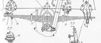
In this article we will look at the front and rear suspension of the ZIL-130, which consists of two longitudinal leaf springs and two telescopic shock absorbers. The rear suspension of the ZIL-130 consists of two main and two additional leaf springs.
The front and rear springs consist of T-shaped sheets and are installed on the ZIL-130 chassis. Maintenance of the ZIL-130 suspension includes lubricating the spring pins and checking the fastening of the springs and shock absorbers.
Tightening of stepladders is carried out in the following order:
1) tighten the front and rear nuts evenly with a tightening torque of 250-320 N*m.
2) check the tightness of the stepladder nuts securing the ears of the front and rear springs.
Tightening must be carried out before the spring washers of the ZIL-130 suspension are compressed. Constriction is not advisable.
3) Filling of shock-absorbing fluid into the shock absorber is carried out according to the lubrication chart. The shock-absorbing fluid is changed on the removed shock absorber.
To fill the shock-absorbing fluid, place the shock absorber vertically and secure it to the lower eye. Raise the shock absorber rod to the highest position, then unscrew the reservoir nut. To fill the working cylinder, it is necessary to remove the piston rod and pour 0.41 liters of shock-absorbing fluid into the cylinder, which should completely cover it. We drain the excess fluid into the shock absorber reservoir. The shock absorber is assembled in the reverse order. When pouring fluid, do not allow dirt and sand to get into the shock absorber, as this can lead to rapid and premature wear.
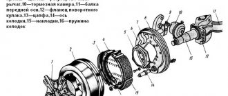
ZIL car suspension: a - front; b - rear; 1 and 25 — front brackets; 2, 12, 27 and 35 - stepladders; 3 — front spring; 4 — lining clamp; 5 and 8 — spring buffers; 6 and 2 (9 - lining; 7 - shock absorber; 9 - clip; 10 and 33 - spacers; 11 and 32 - rear brackets; 13 and 36 - spring ear pads; 14 and 57 - spring ears; 15 and 38 - ear bushings; 16 and 40— spring pins; 17 and 39—oil nipples; 18—rubber bushing; 19—shock absorber pin; 20 and 41—crackers; 21 and 42—cracker pins; 22 and 43—liners; 23 and 44—pinch bolt bushings; 24 and 45 — tie bolts; 26 — additional spring bracket; 29 — additional spring; 30 — intermediate sheet; 31 — rear spring; 34 — stepladder lining.
Source
Design features
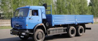
This truck was equipped with an 8-cylinder carburetor four-stroke V-shaped overhead valve ZIL-130 engine with a power of 150 hp. With. at 3200 rpm (with limiter), maximum torque 41 kgm at 1800 rpm, compression ratio 6.5 and displacement 5969 cm³.
The ZIL-130 truck was equipped with power steering, a synchronized 5-speed gearbox, and a three-seater cab with a windshield washer. An engine pre-heater was installed on the part. Then they began to install transistor ignition, an alternating current generator, and a modified instrument panel. Then a modified design of the driveshaft joints and other innovations were applied. The cabs of early cars had two ventilation hatches in the cab roof and an air duct hatch on the left side of the cab above the clutch pedal. Then this hatch was removed and the structure was removed. In the seventies, they stopped installing first the left ventilation hatch, and then the right one. Until 1970, flatbed trucks had a side height of 685 mm, later the side height was reduced to 575 mm.
Specifications
| Vehicle type | Cargo |
| engine's type | carburetor four-stroke |
| Load capacity, kg | 6000 |
| Passenger capacity | 3 |
| Own weight, kg | 4980 |
| Total weight, kg | 10980 |
| Dimensions, mm | |
| length | 6675 |
| width | 2500 |
| height | 2350 |
| base, mm | 3800 |
| Track, mm | |
| front wheels | 1800 |
| rear wheels | 1790 |
| Minimum turning radius, m | 8,0 |
| Maximum speed, km/h | 90 |
| Minimum ground clearance, mm | 270 |
The ZIL-130 car was initially equipped with an eight-cylinder 4-stroke engine with a capacity of 148 horsepower (3000 rpm). The working volume reached 6 liters. The engine lubrication system was combined, with splash and pressure. The engine power supply system is forced, the cooling system is liquid.
The suspension was dependent, the frame consisted of steel spars with five cross members. Starter 1.5 hp turned on via a traction relay. Known to everyone, the ZIL-130 truck became a breakthrough in Soviet mechanical engineering. Along with it, three-seater cabins, a hydraulic power steering wheel, a gearbox that included helical gears and synchronizers, an engine pre-heater, glass washers and more appeared.
In 1974, it was decided to use a more economical engine type for some models. Thanks to this replacement, the truck's efficiency also increased. This unit was a ZIL-157 with 6 cylinders arranged in a row, the power was 110 horsepower. The engine continued to be powered by A-72 gasoline.
Technical characteristics of diesel variations of ZIL
| Model | ZIL-MMZ-554 | ZIL-MMZ-555(A) | ZIL-MMZ-555K |
| Basic chassis | ZIL-130B/ZIL-130B2 | ZIL-130D(ZIL-130D1) | ZIL-130K |
| Engine | ZIL-130 | ZIL-130 | ZIL-157 |
| Engine horsepower | 150 | 150 | 110 |
| Engine power in kilowatts | 110,4 | 110,4 | 80,9 |
| Maximum torque(Newton meters) | 401,8 | 401,8 | 343 |
| Maximum speed | 90 | 90 | 90 |
| Fuel consumption N liters per 100 kilometers | 37 | 37 | 37 |
| Gearbox type | 5-speed manual | ||
| Dimensions | |||
| Wheelbase | 3 800 mm. | 3 300 mm. | 3 300 mm. |
| Car dimensions | |||
| Length | 6,675 mm. | 5 475 mm. | 5 475 mm. |
| Width | 2,500 mm. | 2,420 mm. | 2,420 mm. |
| Height | 2 400 mm. | 2,510 mm. | 2,510 mm. |
| Platform dimensions | |||
| Length | 3,752 mm. | ||
| Width | 2 325 mm. | ||
| Height | 575 mm. | ||
| Square | 8.7 m3 | ||
| Body volume m3 | 5 | 3 | 3 |
| Body lift angle | 50o | 55o | 55o |
| Wheel formula | 4*2 | 4*2 | 4*2 |
| Tire size | 260-508Р | 260-508Р | 260-508Р |
| Technical dimensions of truck cranes ZIL-130 KS-2561D and KS-2561DA | |||
| Base | ZIL-130 | ||
| Switch installation type | Main | Non-retractable boom | |
| Replaceable | With extended boom, with extended boom and jib | ||
| Main boom length | 8 m. | ||
| Departure | 3.3 – 7 m. | ||
| System load capacity | 1,6 | ||
| Ascent/Descent Speed | 02 – 5.3 m/s | ||
| Maximum lift height | 15 meters | ||
| Dimensions with boom lowered | |||
| Length | 10 600 mm. | ||
| Height | 3 650 mm. | ||
| Width | 2,500 mm. | ||
| Weight | 8.8 tons |
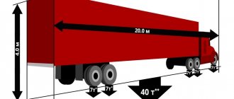
dimensions
Engine
The ZIL-130 truck was equipped with a carburetor eight-cylinder 4-stroke V-shaped overhead valve engine of the same brand - ZIL-130.
| Number of cylinders | 8 |
| Cylinder arrangement | V-shaped |
| Operating procedure | 1-5-4-2-6-3-7-8 |
| Displacement l | 6,0 |
| Compression ratio | 6,5 |
| Power kW (l,s) | 110 (150) |
| RPM at maximum power | 3100 |
- Working volume – 5969 cm³.
- Power – 150 horsepower, at 3200 rpm (with limiter).
- Cylinder diameter – 100 mm; The piston stroke in the cylinder is 95 mm.
- Compression ratio - 6.5.
- Maximum torque at 1800/2000 rpm. – 401.8 Nm (41 kgf-m).
- Fuel consumption is 29 liters per 100 km, with an average vehicle speed of 60 km/h.
- The location of the cylinders in this engine is at an angle of 90 degrees.
The cylinder block has liners, with rubber sealing rings in their lower part. There are two cylinder heads, they are made of aluminum alloy with insert seats and valve guides. The pistons are made from the same aluminum alloy. There are three piston compression rings. 2 upper ones are chrome-plated cast iron, and one oil scraper is steel, composite, chrome-plated. Piston pins are steel, floating, hollow.
The connecting rods are made of steel, I-section, with lubricated piston pin. Connecting rod and main bearings are thin-walled, interchangeable; liners - steel-aluminum (steel tape and aluminum alloy). Crankshaft - steel, forged, five-bearing, with lubrication channels; necks with dirt traps. The flywheel is cast iron, equipped with a steel ring gear for starting the engine from the starter.
The camshaft is steel, five-bearing. The valves of the ZIL-130 engine have the following design.
Intake - located in the cylinder heads. They are driven by a single camshaft. Exhaust outlets are hollow, cooled, with heat-resistant surfacing; have a mechanism for forced rotation of the valve during operation. The pushers are mechanical, made of steel, coated with special cast iron. The valve rocker arms are steel, with bronze bushings.
The gas pipelines of the ZIL-130 engine are as follows: intake - made of aluminum alloy, common to each of the cylinder rows, with a liquid cavity for heating the fuel mixture, located between the block heads; graduations - made of cast iron; one on each side of the cylinder block.
The fuel tank of the ZIL-130 car is installed under the platform on the left side member and has a volume of 170 liters. The power system uses the principle of forced fuel supply; the B-10 fuel pump is a diaphragm pump, with a lever for manual pumping of gasoline. Heating of the fuel mixture - in the intake gas pipeline, which has a special liquid cavity for heating, the fuel mixture is heated.
In 1974, it was decided to use a more economical engine type for some models. Thanks to this replacement, the truck's efficiency also increased. This unit was a ZIL-157 with 6 cylinders arranged in a row, the power was 110 horsepower. The engine continued to be powered by A-72 gasoline.
The cooling system of the ZIL-130 engine is liquid, closed, with forced circulation. A tubular-ribbon radiator, serpentine, three-row, is installed. The thermostat (with solid filler) is installed in the outlet pipe of the liquid cavity. Blinds – folding, vertical, controlled from the driver’s cab. The centrifugal water pump is driven by a belt from the crankshaft pulley, together with a six-bladed engine fan.
Gear box
ZIL-130 vehicles are equipped with a five-speed manual gearbox. The gearbox is equipped with two inertia-type synchronizers for engaging second and third, fourth and fifth gears. The main gear is double, with a pair of bevel gears with spiral teeth and a pair of cylindrical gears with helical teeth, with a gear ratio of 6.32.
The clutch is dry, single-plate, with a spring-loaded torsional vibration damper. The number of pairs of rubbing surfaces is 2. The drive is distributed to the rear axle, the front axle is the steering axle.
There are two cardan shafts, open type, with an intermediate support on the frame. There are three universal joints, on needle bearings, with a constant supply of lubricant. Rear axle housing – steel, stamped, welded. A bevel differential is installed, symmetrical, with four satellites. The axle shafts are completely unloaded. The standard tire size is 260x508.
Brake system
1 - compressor; 2 - pressure gauge; 3 — compressed air cylinders; 4 — brake chambers; 5 - connecting head with disconnecting collapse; 6 - hose; 7 — brake valve (control valve); 8 — brake pedal;
The truck's pneumatic braking system operates on drum mechanisms. The working brake system is a shoe, drum type; acts on all wheels, its drive is pneumatic. The parking brake system is also of the drum type, acting on the transmission; its drive is mechanical. A two-cylinder air compressor is installed, with liquid cooling of the head and block.
Air compressor pistons are made of aluminum alloy, with floating piston pins. The compressor is driven by a belt from the water pump pulley; The compressor is lubricated by the engine lubrication system, under pressure and splash.
Cabin
The cabin of ZIL-433360 vehicles is all-metal, three-seater, with a whole panoramic non-opening glass wind window of the “Triplex” type.
The cabin doors have sliding glass and rotating window windows. Raising the door windows and securely fixing them in the raised position is carried out by single-lever window lifters.
The cabin doors, left and right, have locks that can be opened from the outside with a key and from the inside with a handle. The lock stopper in the down position prevents the doors from opening from the outside.
To open the rotary window of the door, you need to turn the locking handle by first pressing its button. Electric cab windshield wiper. The driver's seat is equipped with a suspension mechanism with adjustable stiffness depending on the weight; before sitting on the seat, the driver must turn knob 2 to set pointer 3 against the number on the scale corresponding to the driver's weight. The suspension can be locked, while the seat is fixed in a single (height) position.
The adjustment provides several fixed positions of the backrest and seat cushion. The cabin heater is designed to supply warm air into the cabin and heat the windshield glass in case it freezes. The tail of the car is of an integral type, folds to the front.
5.2.4. Elastic suspension elements and their calculation. Leaf springs
Leaf springs are the most common among elastic elements. Their positive properties are relatively simple manufacturing technology, ease of repair and the ability to serve as a guide device. The disadvantage of leaf springs is their high metal consumption and insufficient service life. The amount of potential energy during elastic deformation of a spring is 2–3 times less than that of torsion bars and springs. However, both springs and torsion bars require a linkage guide, which increases the weight of the suspension. The most common leaf springs are:
- semi-elliptical (swinging earring) fig. 5.4.;
- cantilever (console);
- quarter (pinched).
The most common of them is a semi-elliptical spring, the earring of which has an inclination of about 5°, and with a maximum deflection of up to 40°. The sheets are stretched under the action of forces S and due to this the stiffness of the spring increases. Currently, springs are used in the eyes of which rubber bushings are installed, which reduces twisting forces when axles are misaligned. Friction between the sheets negatively affects the operation of springs, so they are lubricated with graphite lubricant, and non-metallic gaskets are used for passenger cars. At the ends of the spring leaves
5.2.2.2. Elastic characteristic with two elastic elements
We construct an elastic characteristic with 2 elastic elements (spring and buffer) in the following sequence (Fig. 6.2):
- we find point A using the coordinates fst and G2a, having previously determined fst using formula (2.1), and G2a by finding the total mass of the car per the design spring of the car, and the stiffness in this section will be equal to:
- according to the found value of fst, depending on the type of car and the recommendations given above, we determine fd=fst fd=81mm;
- the suspension stiffness remains constant and equal to Cp1 up to the load G”=1.4G2a, i.e. before the buffer (stroke limiter) comes into operation. Then the suspension deflection in the area from G2a to G” will be:
and deflection during operation of the travel limiter:
- Using coordinates G” and fox we build point B;
- given the value of the dynamic coefficient KD = 2.5¸3, we find Gmax = kD * G2a and the stiffness of the suspension with a travel limiter (buffer) Cp2 using the formulas:
The maximum movement of the wheel from the lower extreme position of the wheel up to the stop will be found using the formula:
- Using the coordinates Gmax and fmax we construct point C.
Elastic characteristics of a suspension with two elastic elements.
rice. 5.2.