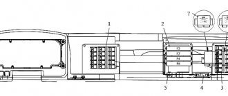
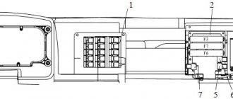
On vehicles with engines of environmental class 5 and 6, an electronic control unit for electrical equipment (ECU) is installed (see Fig. Location of fuses and relays with an electronic control unit).
Location of fuses and relays with electronic control unit
1 - Relay behind the switch panel; 2 - fuse block (F3, F7, F6); 3 — electronic control unit for electrical equipment; 4 - fuse F1, 5 - horn relay; 6 — relay for turning on the coupling headlight; 7 – starter relay; 8 – alarm relay.
Relay behind switch panel
Relay behind the switch panel for vehicles with engines of environmental class 5 1 - ECU relay (for certain configurations); 2 — ECU relay (for individual configurations); 3 — braking relay; 4 — fuel heating relay; 5 — relay for switching on instruments and starter; 6 — battery switch relay; 7 - power control relay after locking the instrument switch and starter; 8 - 12 V socket relay; 9 — windshield wiper stop relay; 10 - radio disconnect relay
Relay behind the switch panel for vehicles with engines of environmental class 6 1 - Clutch relay; 2 — starter blocking relay; 3 — pump power relay; 4 — relay for the heated line to the nozzle; 5 — relay for the heated line from the pump to the tank; 6 — fuel heating relay; 7 — relay for switching on instruments and starter; 8 — battery switch relay; 9 — power control relay after locking the instrument switch and starter; 10 - 12 V socket relay; 11 – relay for the heated line from the tank to the pump; 12 — radio disconnect relay; 13 — windshield wiper stop relay; 14 - heater relay
Where is the starter relay located on KAMAZ?
How to check, connect the signal, ignition, starter relay......
Long-range. We are starting KamAZ after 6 months of inactivity. Relay repair. Bad mass
How to connect a 4- and 5-pin relay. Why?
How to remove the starter on a Kamaz car (Theory)
The starter does not work. The starter does not turn. The starter relay does not retract.
- Power of KAMAZ 740
- Where is the candle at KAMAZ
- Repair of Euro KAMAZ shaft
- Tank capacity KAMAZ 55102
- Control fuel consumption of a KAMAZ 6520 vehicle
- Dismantling the KAMAZ compressor
- Pre-launch device for KAMAZ
- KAMAZ days of downtime
- KAMAZ shock absorbers for UAZ
- A number of KAMAZ models
- How to rebuild a KAMAZ engine video
- KAMAZ trucks from state storage
- Truck crane ks 35714 KAMAZ
- Fuel equipment bosch KAMAZ euro 4
- Semiconductor diode KAMAZ
Home » Clips » Where is the starter relay on KAMAZ
Fuse F5
Fuse F5 is installed on the front panel of the cab.
Fuse F5 1 - to fuse block F4; 2 - fuse F5; 3 - jumper; 4 — “Generator-fuse” wire; 5 — wire “Battery - fuse”; 6 - fuse wire; 7 - to fuse block F1; 8 - fuse wire
1 – Relay behind the switch panel; 2 - fuse block (F2, F3, F4, F6); 3 – relay block; 4 - fuse F1; 5 – starter relay; 6 – alarm relay; 7 – windshield wiper relay; 8 – turn signal interrupter relay.
Relay behind switch panel
1, 2, 3, 4 - See the Table of applied relays; 5- fuel heating relay; 6 - ECU relay; 7 — relay for daytime running lights; 8 — platform stop sensor relay; 9 — rear fog lamp relay; 10 - oil separator relay
Table of relays used
| Pos. | For Cummins engines | For KAMAZ engines |
| 1 | ABS relay | |
| 2 | Starter Interlock Relay | ABS relay |
| 3 | Brake relay | |
| 4 | Clutch relay | Secondary Brake Relay |
Failure options
There are no spare parts that last forever, so it is important to “catch” in time the moment of breakdown of an important starting unit that slows down the operation of the entire truck. Why does the relay break?
- Internal burnout of the nickel plates occurs.
- Often the fragile winding burns out.
- Metal fatigue, subsequent destruction of metal components.
The primary symptom of a breakdown is the lack of engine response to turning the ignition key. When several attempts end in nothing, you should prepare for repairs. The starter itself is designed quite simply; with instructions, even an amateur can disassemble it and fix the problem. The most important thing is to dismantle it correctly and then connect all the components correctly. Initially, the location of the breakdown is determined. The search most often begins at the ignition switch - the initial boundary of the electric current. The surest symptom is the absence of engine starting sounds when you turn the key. Clicks, noise of a rotating shaft, you can try to close the bolts on the back with a metal object, applying voltage directly to the windings. Any damage is clearly visible only after disassembly. You can only check the winding remotely using an ohmmeter. The resistance of the housings at the ends must reach at least 10 kilo Ohms; a lower value means a malfunction of the windings.
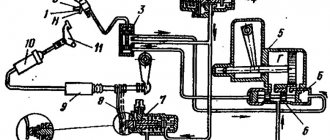
Any movement of a car begins with the start of the internal combustion engine. Starting the engine is the process of rotating the crankshaft until the fuel mixture ignites. This is exactly how the starting system works, taking about a second or two if the engine is fully operational. The launch system is designed in a rather complex manner, consisting of many small, but very significant parts. Among them, the starter retractor relay clearly stands out. A small unsightly detail triggers the entire mechanism, playing the most important role in this process. If other spare parts are only marginally involved in the starting mode, the inoperative state of this component can completely paralyze the vehicle. Kamaz is equipped with a double “portion” of the starting mechanism, like many other trucks. This structure is primarily associated with a more complex injection system for truck engines.
Kamaz has its own power supply system, based on the principle of enhanced torque. Due to the difficult operating conditions of tractors, intense uninterrupted operation, and frequent starting processes, it is necessary that a spark appears regardless of air temperature, humidity, rarefied air, and voltage inside the contacts. Therefore, among the main elements of the Kamaz electric starting system, the following can be distinguished:
- Directly the starter.
- Rechargeable batteries (KAMAZ has two installed - main, backup).
- Instrument shutdown system.
- External trigger socket.
- Blocking relay.
With proper maintenance and proper operation, these units work for a long time. It is very important to ensure proper external maintenance: monitor the processes of oxidation, burnout, and chafing of wires.
Fuse F5
Fuse F5 is installed on the front panel of the cab.
Fuse F5 1 - To fuse block F4; 2 - fuse F5; 3 - jumper; 4 — “Generator-fuse” wire; 5 — wire “Battery - fuse”; 6 - fuse wire; 7 - to fuse block F1; 8 - fuse wire
The Kamaz 65115 dump truck has been produced since 1995 with various engines of Euro 3, Euro 4 class. In this article you will find a description of fuses and relays Kamaz 65115 of Euro 3 and Euro 4 class, as well as for all similar KamAZ 4318, 5320, 65117, 6520 models etc. by emission level, with block diagrams, their locations and photographs.
p, blockquote 1,0,0,0,0 —>
p, blockquote 2,0,0,0,0 —>
The purpose of fuses and relays may differ from those shown. Check the purpose with your documentation or diagrams on the back of the protective cover or inside the unit.
p, blockquote 4,0,0,0,0 —>
General layout of blocks
p, blockquote 5,0,0,0,0 —>
p, blockquote 6,0,0,0,0 —>
Description
Troubleshooting in the KamAZ electric starting system
The engine starting system of a KamAZ vehicle can be in three alternative states: serviceable, operational and faulty (failure).
When in good condition, the starting system ensures the engine starts, and the condition of all devices meets the requirements of the technical specifications.
When in working order, the system ensures reliable engine starting, but the technical condition of some devices does not meet the technical conditions.
In the event of a malfunction (failure), starting the engine is impossible due to a malfunction of one or more system devices.
We will not consider the serviceable state of the system, since we are not tasked with determining the failure-free operation period of the system by the number of starts or by the mileage of the vehicle. To perform most tasks, it is enough to have the system in working order, when the system ensures reliable engine starting. Therefore, first of all, we will consider system failure and possible malfunctions, and indicate ways to quickly identify and eliminate them.
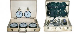
The system consists of seven devices, each of which affects the operation of the entire system. Therefore, in order to optimize the troubleshooting process, it is necessary to time each test and evaluate its impact on the performance of the starting system:
Checking batteries
Remove the cover from the battery socket. By external inspection, check the condition of the terminals of the tips and the tightness of their fastening to the pole terminals (Fig. 1). Based on the density of the electrolyte, the degree of discharge of the battery should be determined. Check time is about 5 minutes;
Checking the presence of voltage on the ammeter
Unscrew the bolts securing the prior shield and tilt the shield towards you or place it on the steering column. In this case, free access to the ammeter leads is available. Connect a test light in series to the input and output of the ammeter. If the light on the “+” of the ammeter is on, then the circuit up to the ammeter is working, and vice versa. Then check the “-” ammeter. If the control lamp is on, it means that current is passing through the ammeter, and faults should be looked for further along the circuit. If the light does not light, then the ammeter is faulty. This test without replacing the ammeter takes up to 2 minutes;
Checking the instrument switch and starter
Before checking this device, it is necessary to carry out preparatory work to ensure access to the terminals. To do this, you need to remove the guard panel for the electric motors of the cabin heating system, unscrew the nut securing the instrument switch and starter and remove the device from the panel, leaving it on the wires (Fig. 2). Remove the red wire from the “AM” terminal and check the presence of voltage with a test lamp. If the lamp is on, it means that the circuit to the instrument switch and starter is working. Then you need to connect the red wire to the “AM” terminal, turn the key in the instrument and starter switch to the second position and check the “ST” terminal (green wire) with a light bulb. If the lamp is on, it means that the instrument and starter switch is working properly.
Relay box behind switch panel
p, blockquote 8,0,0,0,0 —>
Scheme
p, blockquote 9,0,0,0,0 —>
p, blockquote 10,0,0,0,0 —>
Purpose
- ABS relay
- Starter Interlock Relay
- Brake relay
- Clutch relay
- Fuel heating relay
- EFU relay
- Daytime running light relay
- Platform Stop Sensor Relay
- Rear fog lamp relay
- Oil separator relay.
General information about the starting system
The electrical wiring on KAMAZ is a rather complex system, and the starter in it is, in fact, an electric motor equipped with a traction relay. You can also find out on our website who needs a KAMAZ 5320 wiring diagram and why
- It is located on the flywheel housing on the driver's side.
- Fastens with 3 bolts and a stud.
- The series starter electric motor operates on direct current .
Starter design
In addition to the housing itself, it contains the following components:
- anchor,
- excitation winding,
- brush and commutator,
- drive shaft,
- two covers (front and back).
The device body acts as a magnetic circuit with cores attached to it. The front starter cover directly covers the drive mechanism, while the rear cover covers the assembly with brushes and commutators. A rectangular copper wire is used in the excitation winding .
Fuse box
p, blockquote 12,0,0,0,0 —>
p, blockquote 13,0,0,0,0 —>
General designation
p, blockquote 14,0,0,0,0 —>
row F2
p, blockquote 15,1,0,0,0 —>
| 1 | Reserve |
| 2 | Low beam right, corrector |
| 3 | Low beam left |
| 4 | Rear fog light |
| 5 | High beam right, high beam warning lamp |
| 6 | High beam left |
| 7 | Reserve |
| 8 | Right side marker, instrument lighting |
| 9 | Left clearance |
| 10 | Fog lights |
| 11 | Central light switch, spotlight |
| 12 | Lighthouses |
| 13 | Sleeping place, engine compartment lamp, road train lights |
row F3
p, blockquote 16,0,0,0,0 —>
| 1 | Wheel lock, radio |
| 2 | Gas leak alarm (on gas vehicles) |
| 3 | Power take-off, daytime running lights, winch |
| 4 | Electromagnetic engine cooling clutch, reversing lights |
| 5 | Ground switch relay coil |
| 6 | Buzzer (sound signal), brake signal relay coil |
| 7 | Generator excitation winding, tire inflation |
| 8 | Courtesy lamps, glove compartment lighting, instrument cluster power supply |
| 9 | Pendant lamp socket, heater motors |
| 10 | Horns, "+" trailer sockets, brake lights |
| 11 | Driver blower fan |
| 12 | Reserve |
| 13 | Heated mirrors, heated seats |
row F4
p, blockquote 17,0,0,0,0 —>
| 1 | Reserve |
| 2 | Electronic speedometer, electronic tachometer |
| 3 | Tractor ABS |
| 4 | Trailer ABS |
| 5 | Instruments, electronic speedometer, electronic tachometer |
| 6 | Tractor ABS, engine brake relay (valve) |
| 7 | Trailer ABS |
| 8 | Gas level sensor (on gas vehicles) |
| 9 | Wiper power supply |
| 10 | Engine control unit power supply |
| 11 | Electric flare device |
| 12 | Reserve |
| 13 | Reserve |
series F6 (for KAMAZ engines)
p, blockquote 18,0,0,0,0 —>
| 1 | The engine control unit |
| 2 | The engine control unit |
| 3 | Diagnostic connector |
| Brake relay | |
| 4 | Warning lamps |
| 5 | Warning lamps |
| 6 | Air suspension control unit |
| 7 | Urea pump |
| 8 | Urea pump |
| NOx sensor | |
| 9 | Reserve |
| 10 | Reserve |
| 11 | Automatic transmission control unit |
| 12 | Retarder braking signal |
| 13 | Automatic transmission control unit |
row F6 (for CUMMINS engines)
p, blockquote 19,0,0,0,0 —>
| 1 | The engine control unit |
| 2 | The engine control unit |
| 3 | Diagnostic connector |
| 4 | Reserve |
| 5 | Air suspension control unit |
| 6 | Air suspension control unit |
| 7 | Dosing pump |
| 8 | Urea heating line relay |
| Dosing pump | |
| 9 | Reserve |
| 10 | NOx sensor |
| 11 | Automatic transmission control unit |
| 12 | Automatic transmission, retarder brake signal |
| 13 | Automatic transmission control unit |
External and internal lighting system KamAZ-43118
In addition to external lighting, this system is also responsible for lighting inside the vehicle’s cabin. It includes the following devices:
- headlights;
- fog lights;
- front lights;
- rear lights;
- engine compartment lamp;
- lamp for lighting the glove compartment and bed;
- instrument lighting lamp;
- cabin lighting lamp;
- portable lamp.
It has the following scheme:
- right fog lamp
- left fog lamp;
- right headlight
- glove box lamp;
- lamp switch;
- road train lights;
- road train light switch;
- heater motor relay;
- left cockpit light;
- right cockpit light;
- left headlight;
- fog light switch;
- brake signal relay;
- trailer solenoid valve switch;
- rear right lamp
- rear left lamp;
- front right lamp
- front left lamp;
- combination light switch;
- fuse 13.3722 (7.5 A);
- fuse PR 310 (10 A);
- instrument lighting switch;
- engine compartment lamp;
- hazard warning light switch;
- portable lamp socket;
- seven-pin socket;
- oil pressure indicator;
- fuel level indicator;
- speedometer;
- tachometer;
- coolant temperature gauge;
- ammeter;
- pressure gauge;
I. to the instrument and starter switch
All devices, except for the glove compartment light, are connected using a single-wire circuit. As for the glove box lighting lamp, its negative contact is connected to the fuse block.
As for the low and high beams (numbers 3,11), dimensions, fog lights (1,2), they are turned on and off by a combination switch (19) connected through an ammeter.
To protect low beam headlights, as well as fog lights, from short circuits, they are powered through PR310 thermobimetallic fuses. High beams have their own fuses.
The size circuits and instrument lighting lamps are also protected from short circuits by thermobimetallic fuses of type 13.3722.
Second relay block
Scheme
p, blockquote 20,0,0,0,0 —>
p, blockquote 21,0,0,0,0 —>
Decoding
- power control relay after locking the instrument switch and starter
- instrument switch and starter relay
- battery switch relay
- brake signal relay
- reverse relay
- horn relay
- low beam relay
- high beam relay
- rear fog lamp relay
- fog light relay
- side light relay
Warning light circuit diagram
This system controls the rear brakes and turn signals. It serves to notify other road users about the maneuvers the truck is making. The general diagram of this system is shown in the figure below:
The numbers on the diagram indicate:
- left lamp;
- right lamp;
- turn signal and hazard warning relay;
- fuse PR 119 (6 A);
- light switch;
- fuse 13.3722 (7.5 A);
- fuse PR 310 (10 A);
- hazard warning light switch;
- turn signal right
- left turn indicator;
- rear left lamp
- rear right lamp;
- brake light switch;
- trailer solenoid valve switch;
- brake signal relay;
- sound signal (buzzer);
- 18, 19 — switches for pressure drop alarms in the brake air drive receivers;
- parking brake warning switch;
- relay-interrupter for the parking brake system activation indicator;
- reverse light switch;
- reversing light;
- trailer socket 24 V;
- center differential lock warning switch;
- 27, 28 — signaling units;
- oil filter clogged warning switch;
I. to the instrument and starter switch;
II. to the coolant temperature gauge;
Fuse F1
Scheme
p, blockquote 23,0,0,1,0 —>
p, blockquote 24,0,0,0,0 —>
Description
- nutrition
- radio equipment
- ECU circuit wiring harness
- to fuse block F2
- dryer cable
- instrument and starter switch
- starter relay
- to fuse block F3 after the instrument switch and starter
- to fuse block F3 to the instrument switch and starter
- fuse 60 A
- fuse 30 A
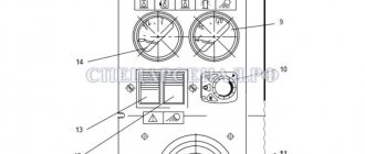
Instrumentation system
As you might guess from the name, this system is designed to service various instrumentation, indicators and sensors. Instruments are located on the dashboard of the car, and sensors are located in its various components and mechanisms.
The electrical diagram of this system is as follows:
The numbers on the diagram indicate:
- fuel level indicator;
- fuel level sensor;
- fuse 13.3722 (7.5 A);
- coolant temperature indicator sensor;
- coolant overheat sensor;
- emergency oil pressure sensor;
- oil pressure indicator sensor;
- oil pressure indicator;
- 11 — blocks of warning lamps;
- coolant temperature gauge;
- generator;
- tachometer;
- speedometer;
- speedometer sensor;
I. to the instrument and starter switch
Fuse under the hood
The power fuse box can be installed on the cab front panel.
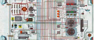
To connect all the electrical systems and devices in the car, an electrical network is used, which allows you to bring all the components together. The KAMAZ-65115 color wiring diagram is a diagram indicating all electrical elements, the use of which is important when repairing wiring. You can learn more about the elements of the circuit, as well as wiring faults, from this material.
Functional
There are two types of relays. The first directly turns on the starter, starting the main mechanism. Located inside the engine. The second, actually the retractor, is located on the starter itself, performing a more comprehensive functionality.
- The electric current between the electromagnet and the starter motor must be properly redistributed. A malfunction of the retractor function leads to an imbalance, disrupting the starting system.
- The starter has several main components responsible for starting the engine. The relay helps to correctly synchronize the work between important compartments of the starting mechanism.
- A simple mechanical moment: the flywheel teeth mesh with the Bendix gears. Bendix is a part that transmits torque and regulates high engine speeds. When initially starting, the engine always starts to run at higher speeds. It is impossible to operate the internal combustion engine in this mode all the time, so the speed gradually drops, becoming idle.
- After starting the motor, the gears must be returned to their original state, since the mechanism has completed its functionality until the next start.
In other words, summarizing the above, we can summarize the operation of the retractor relay as follows: the working process of the gears needs to be synchronized, the bendix is removed from the flywheel after working out. Sometimes it is simply called traction. Traction is the most important force in modern cars, so the parts that work to create traction will play a primary role.
Being an independent vital part, the level of operation of the component will be checked at the next stage of maintenance. Carrying out electrical diagnostics is an important stage in the overall diagnostics of a car. Sometimes, due to a small insignificant unit, an entire large mechanism breaks down, paralyzing the operation of the tractor. In addition, trucks typically work harder than cars, so early detection of possible breakdowns is especially important.
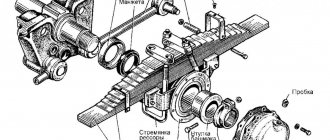
The part has an electromagnetic base, retracting and holding windings, a starter switching circuit, and a return spring core. Externally, the part resembles a sleeve, blank on one side. The second side mates with the fork, which pushes the nose part like a lever. The fork is fixed on the central part of the axis, where the bendix moves, after which the electromagnet is triggered. In view of such an intricate structure, let’s look at the process of the Kamaz plant in a little more detail.
- Turn the ignition key. It is worth noting that in the warm season, the ignition “seizes” better precisely due to the most favorable temperature for creating an electromagnetic field.
- The magnetic field quickly gains momentum, pushing the anchor. The starter armature serves as a conductor between the fastening elements and the coupling, representing an axis made of alloy steel, and has grooves that accommodate the armature windings. The armature gradually compresses the return spring.
- The end of the fork moves towards the flywheel. By pushing out the gear, moving the bendix, it engages the flywheel ring gear. The flywheel and bendix break very rarely, the parts are very durable, and among other things, their interaction occurs quite smoothly, increasing the service life.
- Once the engagement process is complete, the contacts are closed, integrating the operation of the solenoid relay circuit.
- The retracting winding is very powerful, it can overcome the resistance of the return spring, so after starting it turns off, fixing the armature tightly.
- After turning off the ignition, the reverse process occurs: the parts are disconnected from each other, the current is turned off, the starter armature takes its original position, and the bendix leaves the flywheel clutch.
The solenoid relay is a reliable part that lasts a very long time. Often, a truck will go through many cycles before major maintenance before unexpected problems arise with a given starter assembly. The most likely failure is for any other spare parts that have a more severe mechanical interaction. The design of Kamaz's electromagnetic parts is very reliable.
Features of electrical equipment
Now let's move on to the description of the KAMAZ electrical circuit.
All models of KAMAZ 6520, 55102 and other trucks are equipped with the following subsystems:
- Starting the power unit.
- Turning lights and hazard warning lights.
- Heating unit, power supply system, windshield cleaning mechanism.
- Vehicle interior lighting.
- Head lighting. It includes low and high beam headlights, fog lights if they are installed on the car, brake lights, and dimensions.
- Tidy. This node is considered one of the main ones in the on-board network, since it contains the main sensors, devices and instruments, including a tachometer, speedometer, fuel level sensor, etc. In addition, the control panel has light indicators that turn on when the lighting is activated , handbrake, etc. Thanks to the indicators, the driver can indirectly determine the status of some components.
- Vehicle anti-theft system, if installed.
- Fuse block. This component protects the car's electrical circuits from possible voltage surges. It contains fuses responsible for the operation of the main electrical equipment.
- A control unit, thanks to which the normal operation of the main units and equipment of the car is guaranteed.
- Audio system, if the car is equipped with one.
In order for the KAMAZ electrical circuit to operate in normal mode, the condition of the wiring must be at least satisfactory.
In addition, the operation of the electrical circuit is possible if:
Functional
There are two types of relays. The first directly turns on the starter, starting the main mechanism. Located inside the engine. The second, actually the retractor, is located on the starter itself, performing a more comprehensive functionality.
- The electric current between the electromagnet and the starter motor must be properly redistributed. A malfunction of the retractor function leads to an imbalance, disrupting the starting system.
- The starter has several main components responsible for starting the engine. The relay helps to correctly synchronize the work between important compartments of the starting mechanism.
- A simple mechanical moment: the flywheel teeth mesh with the Bendix gears. Bendix is a part that transmits torque and regulates high engine speeds. When initially starting, the engine always starts to run at higher speeds. It is impossible to operate the internal combustion engine in this mode all the time, so the speed gradually drops, becoming idle.
- After starting the motor, the gears must be returned to their original state, since the mechanism has completed its functionality until the next start.
How to determine the malfunction?
There are several options for diagnosing the health of a car's electrical circuit, which can be done at home. For example, you can check the presence of voltage in a certain area; for this you can use a multimeter or a test light.
So, if the circuit is faulty, the procedure is as follows:
- First, you need to connect one of the probes of the tester or warning lamp to the “-” terminal of the battery; it can also be connected to the truck body.
- The second probe must be connected to the connection of the area being diagnosed, and it is desirable that it be installed as close as possible to either the battery or the fuse.
- If, as a result of the connection, the control light starts to light up or voltage appears on the multimeter display, this means that this section of the circuit is working normally. That is, all elements are connected as needed, and no wiring repairs are required. But it must be taken into account that in some circuits voltage may be present if the ignition key is turned to a certain position.
- Next, the remaining sections of the circuit are diagnosed, the procedure is carried out in a similar way.
- If you find a point where there is no voltage, then most likely the cause of the problem lies between this point and the last area where there is voltage.
- It should be noted that in most cases, problems with wiring are caused by poor contact.
You can also try to find a short circuit in the system at home:
Installation process
Kamaz has a completely dismountable starting system, so repairs, installation, and dismantling can be done independently, taking into account the technological features of the process.
- Initially, it is necessary to cover the contact planes with a special sealant that “eats” excess electromagnetic radiation.
- The relay is connected to the drive lever and secured with nuts.
- Then the main electrical power wire is connected.
- Afterwards, you need to check whether the relay is installed correctly, then it will be impossible to refasten the mechanism without a complete disassembly.
- After the checks are completed, the starter takes its place.
To replace the starter relay, you need to stock up on a set of the following tools: wrenches of appropriate sizes, socket extension, socket, screwdriver. Before starting work, it is necessary to completely eliminate the presence of scale, oxidation of the terminals, discharge of the battery, damaged wiring, and poor contact fastening. Next, we will write out a small checklist for completing the work.
- The negative wire is disconnected from the battery.
- The clamp nuts must be unscrewed slightly so that the threads are slightly loosened.
- We remove the air intake hose, which is first disconnected from the air filter, then from the air intake itself.
- We unscrew the nuts securing the heat-insulating shield, using the socket extension, unscrew the bolt securing the shield and support bracket.
- The thermal insulation shield can be removed by unscrewing the bolts of the lower and upper fastenings.
- The starter output connector is removed, the nut is unscrewed, and the existing wire is removed thanks to the already removed upper bolt. The starter is pulled out carefully vertically.
- The relay is pulled out with a socket wrench, and the fastening nut is carefully unscrewed. Now the fixing bolts can also be removed.
This is what dismantling the old starter looks like. Accordingly, the installation of the new one will be completely mirrored.
A completely different point is the installation of an additional relay, which is already mounted in any convenient place. The most popular location is the washer barrel. You can conveniently route the necessary wires, the main thing is to securely fasten them, avoiding damage.
Video “The process of repairing the lighting and electrical circuit of a KAMAZ vehicle”
Attention: The electronic auto parts catalog is intended for reference purposes! Our company only sells those products that have prices listed.
| Number | 1/38358/71 |
| Name | Bolt M6-6gx10 |
| Quantity per "6520" | 12 |
| Fastener | Yes |
| Material | other metal materials, i.e. not steel, not brass, not light alloy, not copper |
| Coating | galvanizing |
Part number on drawing:
Bolt M6-6gx10
Serial number: 1/38358/71 Quantity per model: 12
In warehouses: 19 pcs.
A story from repair practice
KamAZ injector malfunction
Further from practice, one of these cases of diagnosis and repair. The conclusion of today was a KAMAZ with a CUMMINS engine. The car wouldn't start at all. We are going to Solaryevo, where the transport itself was located. The electrical equipment of the car turned out to be in order, with one exception. A mechanical malfunction of the 4th injector prevented the KAMAZ from starting. With this conclusion and advice on replacing the injector, we turned to the owner of this Pepelatsa. On Saturday evening there are quite a lot of applications and requests for help, so the day again flew by instantly for us, however, just like on the previous days of the week. Good luck to all!
ROSTAR
- V-shaped rods
- Jet rods
- Jet rod repair kits
- Suspension shock absorbers
- Silent blocks
- Steering rods
- Stabilizer links
- Steering rod ends
- Drum brake pads
- Disc brake pads
- Ladder springs
- Towbar pins
- Transmission control drive parts
- Brake chambers, energy accumulators
- Pneumatic hydraulic boosters (PGU)
- Caliper repair kits
- Parts made of polymer composite materials
- Suspension brackets
- Pneumatic springs
- Brake levers
In warehouses: 107 pcs.
In warehouses: 398 pcs.
| Number | 738.3747-20 |
| Name | Relay |
| Quantity per "6520" | 2 |
Part number on drawing:
Relay
Serial number: 738.3747-20 Quantity per model: 2
In warehouses: 370 pcs.
RELCOM
In warehouses: 213 pcs.
In warehouses: 235 pcs.
In warehouses: 27 pcs.
| Number | 733.3747-10 |
| Name | Alarm relay |
| Quantity per "6520" | 1 |
Part number on drawing:
Alarm relay
Serial number: 733.3747-10 Quantity per model: 1
In warehouses: 69 pcs.
In warehouses: 155 pcs.
In warehouses: 7 pcs.
| Number | 901.3747 |
| Name | Relay assembly |
| Quantity per "6520" | 11 |
Part number on drawing:
Relay assembly
Serial number: 901.3747 Quantity per model: 11
Anti-freeze fuse 100-3536010 KamAZ 55102
supplies Anti-freeze fuse 100-3536010 from warehouses in Moscow, Chelyabinsk, Miass, St. Petersburg, Khabarovsk. Check availability with multi-channel phone managers.
Kamaz 55102Wick assembly for KamAZ 55102 / Anti-freeze fuse 100-3536010100-3536030 specify
Kamaz 55102 Nut M8-6N for KamAZ 55102 / Anti-freeze fuse 100-35360101/61008/11 please specify
Kamaz 55102 Spring washer 8 for KamAZ 55102 / Anti-freeze fuse 100-35360101/05166/77 please specify
Kamaz 55102 Bracket for KamAZ 55102 / Anti-freeze fuse 100-35360105320-3536019 specify
Kamaz 55102Bolt M8-6qx70 for KamAZ 55102 / Anti-freeze fuse 100-35360101/60446/21 specify
Kamaz 55102Bolt M8-6qx30 for KamAZ 55102 / Anti-freeze fuse 100-35360101/60438/21 specify
Kamaz 55102 Flat washer 8.45x17x2 for KamAZ 55102 / Anti-freeze fuse 100-35360101/05196/01 please specify
Kamaz 55102 Anti-freeze fuse for KamAZ 55102 / Anti-freeze fuse 100-3536010100-3536010 specify
Kamaz 55102 Measuring rail for KamAZ 55102 / Anti-freeze fuse 100-3536010100-3536046 please specify
Kamaz 55102 O-ring for KamAZ 55102 / Anti-freeze fuse 100-3536010100-3536047 specify
Kamaz 55102 Pin for KamAZ 55102 / Anti-freeze fuse 100-3536010484105 specify
Kamaz 55102Hollow rivet for KamAZ 55102 / Anti-freeze fuse 100-3536010304183 specify
Kamaz 55102Plate for KamAZ 55102 / Anti-freeze fuse 100-3536010100-3512099 specify
Kamaz 55102 Upper housing for KamAZ 55102 / Anti-freeze fuse 100-3536010100-3536020 please specify
Kamaz 55102Ring for KamAZ 55102 / Anti-freeze fuse 100-3536010100-3536025 specify
Kamaz 55102 Traction for KamAZ 55102 / Anti-freeze fuse 100-3536010100-3536024 specify
Kamaz 55102Ring for KamAZ 55102 / Anti-freeze fuse 100-3536010100-3522069 specify
Kamaz 55102Ring for KamAZ 55102 / Anti-freeze fuse 100-3536010100-3536029 specify
Kamaz 55102Clip for KamAZ 55102 / Anti-freeze fuse 100-3536010100-3536028 specify
Kamaz 55102 Thrust ring for KamAZ 55102 / Anti-freeze fuse 100-3536010489305 specify
Kamaz 55102 Plug for KamAZ 55102 / Anti-freeze fuse 100-3536010305062 specify
Kamaz 55102Ring for KamAZ 55102 / Anti-freeze fuse 100-3536010100-3536045 specify
KamAZ 55102 Lower housing for KamAZ 55102 / Anti-freeze fuse 100-3536010100-3536040 please specify
Kamaz 55102 Spring washer 8 for KamAZ 55102 / Anti-freeze fuse 100-3536010305890 specify
Kamaz 55102Bolt M8-6qx20 for KamAZ 55102 / Anti-freeze fuse 100-3536010201456 specify
Kamaz 55102Spring for KamAZ 55102 / Anti-freeze fuse 100-3536010100-3536032 specify
Kamaz 55102Wick for KamAZ 55102 / Anti-freeze fuse 100-3536010100-3536033 specify
Kamaz 55102 Plug for KamAZ 55102 / Anti-freeze fuse 100-3536010100-3536034 please specify
Kamaz 55102 Washer for KamAZ 55102 / Anti-freeze fuse 100-3536010305768 specify