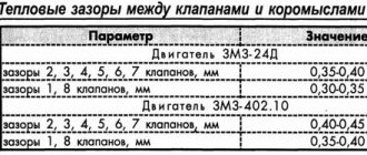
Adjusting the valve clearances with your own hands on the MTZ-80 and MTZ-82 tractors, on which the D-240 engine and its modifications D-243, D-245, D-245L, D-245.2 and D-245.4 are installed, will not be difficult. By following the step-by-step instructions presented in this article, you can easily set the gaps. The clearances should be checked and adjusted every 480 hours of engine operation. Of course, each removal (disassembly) of the cylinders subsequently involves the same actions. It goes without saying that valve knocking is no exception here either. The valve clearance of MTZ-80 and 82 on a cold engine should be no more than 0.25 mm.
Installing the piston of the first cylinder
It is necessary to set the piston of the first cylinder to top dead center. But not at the moment of fuel compression. Because it is very easier to determine when the piston approaches TDC, the exhaust valve will begin to close and the intake valve will begin to open immediately after passing TDC. It is necessary to catch an intermediate position in which both valves are closed. For greater confidence, you can install a stopper located on the adapter plate.
Installing the position stopper of the first cylinder
It turns inside out and turns back in. In this case, it should fall into the groove of the flywheel. But it is not necessary to do this in this position; there is no need for great precision in the position of the piston at TDC.
The piston of the fourth cylinder will be at TDC. At the moment of compression. In this position, both valves of cylinder 4 will be closed and ready for adjustment.
The piston of the second cylinder will be at bottom dead center. At the beginning of the compression stroke, so the intake valve closes and the exhaust valve closes. You can adjust the exhaust valve of the 2nd cylinder
The piston of the third cylinder is at the end of the fuel expansion stroke, therefore the intake valve will be closed and with further movement of the piston towards top dead center the exhaust valve will begin to open, therefore the intake valve of the third cylinder can be adjusted.
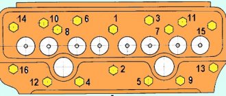
Adjusting the valves in the first position of the crankshaft
Therefore, in this position of the crankshaft, they are adjusted according to the valve count
4 – 6 – 7 – 8
The order of the valves is taken from the front of the engine, that is, from the radiator side.
After adjusting these valves, turn the crankshaft one revolution, that is, 360 degrees.
Second crankshaft position
In this position, the piston of the first cylinder will move to the TDC position at the moment of fuel compression. That is, the intake and exhaust valves will be closed
The piston of cylinder 3 is at bottom dead center. At the beginning of the compression stroke, the exhaust valve is closed
The piston of the second cylinder is at the end of the fuel expansion stroke, so the intake valve is closed
Based on this, we adjust the valves in order
1 – 2 – 3 – 5
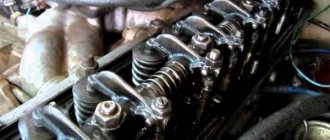
Valve clearances are set using a feeler gauge
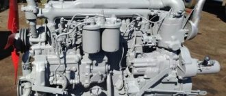
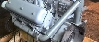
Engine models for MTZ tractors
Most of the cars of the Belarus family are equipped with diesel engines with the names D-240, D-242, D-243, D-244 and D-245.
D-240
MTZ-80 and MTZ-82 are equipped with a D-240 engine with a common combustion chamber, water cooling and an installed mixture formation system with direct fuel injection. The power of the unit reaches 59.25 kW at a rotation speed of 2200 rpm. The first tractors had a thrust of 55.16 kW. Weight is 410 kg.
Technical characteristics of in-line cylinders:
- Working capacity - 4.75 l.
- Diameter - 110 mm.
- The amplitude of piston movement is 125 mm.
MTZ-80 is equipped with a D-240 engine with a common combustion chamber and water cooling.
The motor is heated using an electric torch EFP-8101500 or a pre-heater PZHB-200B. Diesel fuel consumption during operation is 238 g/kWh.
D-242
MTZ and YuMZ tractors are equipped with D-242 engines. They are among the first devices to use a fan mechanism with a diameter of 450 mm and a lightweight crankshaft with a pulley size of 170 mm.
Technical and operational parameters of the D-242 tractor engine:
- Cylinder capacity - 4.75 liters.
- Diameter - 110 mm.
- Piston stroke - 125 mm.
- Fuel consumption - 226 g/kWh.
- Power - 46 kW.
- Rotational speed - 1800 rpm.
- The highest torque is 278 N*m.
- Weight - 430 kg.
D-243
The D-243 engine is intended for tractor equipment designed for 14-20 kN, used with unlimited exchange of air mass without a turbocharger and operated at temperatures of -45...+40°C. The diesel engine is available in 2 modifications: D-243L and D-243.1. On a motor with a P-10UD starting device, the PS is controlled remotely. Modifications 243 and 243.1 are started using a starter 24.3708 and differ in power parameters. Thus, the power of D-243 is 59.6 kW, D-243.1 - 61 kW.
The D-243 engine is used for unlimited exchange of air mass.
Basic indicators:
- Working capacity - 4.75 liters.
- Rotational speed - 2200 rpm.
- The highest power moment is 298 N*m.
- Fuel consumption - 226 g/kW*h.
- Weight - 430 kg.
D-244
The D-244 engine with a crankshaft that does not contain counterweights is equipped with MTZ tractors, mini-tractors and other agricultural machinery. The main differences between the engine and its analogues are:
- Power - 41.9 kW.
- Rotation speed - 1700 rpm.
- Torque - 271 N*m.
Model D-245
The diesel unit D-245 is the latest model in the family. It is produced in the following versions:
- D-245 and 245L - with turbocharging. Options:
- thrust - 77 kW;
- frequency - 2200 rpm;
- highest torque - 384 N*m;
- fuel consumption - 220 g/kWh;
- device weight - 450 kg.
- D-245.2 - with turbocharging and charge air cooling, with a power of 88 kW and a torque of 439 N*m. The weight of the model is 470 kg. Starter 20.37-8 is used as a PS. Turbocharger - TKR-6 or S1470V/8.12 M.
- D-245.4 and 245.5 - with turbocharging. Traction characteristics - 60 and 65 kW at a frequency of 1800 rpm. The calculated maximum moment is 366 and 397 N*m. Turbocharger - TRK-6-01 or S1470V/6.12M.
The D-245 engine is produced with turbocharging and supercharged air cooling.
Design features include:
- Availability of a turbocharger.
- Changes to the supply and return manifold pipes, crankshaft pulley, generator set and water pump.
- Auxiliary V-belt.
- Special nozzles in block supports.
- Cast iron insert under the first ring of the compressor.
- Anti-smoke corrector.
- Improved push-in valve seats and oil pump.
- Lengthening the flywheel pins.
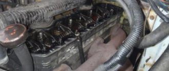
Adjustment of valves
Before starting the adjustment, it is necessary to tighten the rocker shaft mounting bolts. He is released. Therefore, it will not be possible to adjust the valves. It is better to immediately make sure that the connection is reliable. The feeler gauge is inserted between the rocker arm and the end of the valve stem; the adjusting screw is tightened in this way. So that the probe passes between the rod and the rocker with little effort. He should not be pinched and should not walk freely. Once the gap is set. The adjusting screw is locked when the lock nut is removed. In this case, the screw must be held with a screwdriver.
This adjustment procedure is of course simple and convenient. But it is not always possible to remember the order in which the valves are adjusted. And you don’t always have a book or the Internet at hand to remind you. Therefore, you can use a different adjustment procedure.
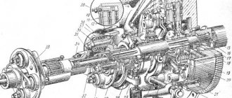
Characteristics of fuel injection pump
The MTZ fuel pump belongs to the category of four-plunger units and is designed to ensure the necessary fuel circulation. In the design of the tractor, it is located in one block with a pumping analogue and a centrifugal regulator. The block is located on the left side of the D-240 engine, secured with bolts to the distribution cover.
Before you figure out how to add fuel to the MTZ injection pump, you need to become more familiar with its characteristics and features. Correct operation of the unit is ensured by the action of the crankshaft, which drives it through a gear mechanism.
Among the most significant characteristics of this important element it is advisable to include:
- manufacturer - Noginsk;
- spare parts catalog number - 4UTNI-1111005-20;
- scope of application - power units of the D series (from 240 to 248.1 modification) for various MTZ models;
- drive type - splined bushing.
The MTZ 82 fuel equipment is not a completely unique development, since it has foreign analogues. An example is the Czech-made PP4M9P1g-4201, which is almost identical in its technical design and characteristics.
Adjusting valves separately on each cylinder
It consists of bringing each piston to TDC at the moment of compression. It is enough just to remember the order of operation of the engine cylinders.
The order of operation of the D240 cylinders.
1 – 3 – 4 – 2
Piston position of the first cylinder
It is necessary to correctly determine the position of the piston of the first cylinder at TDC at the moment of compression. You need to navigate by the valves. When the piston reaches TDC, the intake valve will close and the exhaust valve will be closed. And the moment when the piston approaches TDC, both valves are closed and the rocker arms do not move. For a more precise position, you can set the stopper. It will indicate the exact position of the piston. During one cycle of engine operation, the piston in this case of the first cylinder approaches TDC twice. Therefore, it is very important to establish exactly the position at the moment of compression. When the valves are closed and motionless. The second position is described above. With it, one valve closes and another opens. In this case, we are interested in the first position.
The procedure for adjusting the valves of each cylinder
The valves of the first cylinder are adjusted.
Then the crankshaft is turned half a turn and the valves of cylinder 3 are adjusted.
Another half turn or 180 degrees. The valves of 4 cylinders are adjusted.
half a revolution of the shaft and adjust the valves of cylinder 2.
You can rotate the shaft using the bolt securing the front hub of the crankshaft pulley using a socket and ratchet.
Before cranking the engine, you must pull out the engine stop cable. To avoid the possibility of it starting. And of course put the gearbox in a neutral position. If the engine is equipped with a common rail injection system. Turn off the ignition.
Additional Instructions
Do not tighten the nuts quickly, tightly or with sudden movements. This is done calmly and evenly, in several passes. It is important to provide opportunity and freedom to move the screwed elements. This makes it easier to set their position correctly. The MTZ-82 valve clearance on a cold engine should How to adjust MTZ-82 valves. It is important to tighten the fasteners on a warm engine. How to adjust the carburetor with your own How to set the idle speed on a VAZ 2107. There is a sequence diagram for tightening the cylinder . It can be found in the manual for adjusting the gas distribution mechanism . This scheme allows for high-quality tightening, ensuring ideal tightness of the engine.
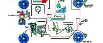
Recommendations for use
The reason for poor braking is oil getting on the working discs, causing the friction linings to slip. Lubricant leakage into the brake drum housings occurs as a result of wear of the oil seals that isolate the transmission oil sump and the oil housing of the differential lock clutch connected to the left brake housing of the tractor. Self-clamping rubber seals are installed in the cup lid; the lid itself is sealed with a rubber ring in the groove of the rear axle housing. If oiling of the mechanism is detected, the unit is disassembled and the cause is eliminated. The parts are washed with gasoline and, after drying, assembled.
Loss of brake performance occurs as a result of wear on the disc linings, as well as the appearance of grooves as a result of wear on the working surfaces. If the total wear of the lining thickness exceeds 8 mm, the friction discs are replaced with new ones. It is recommended to change parts on both sides to ensure simultaneous braking of the left and right sides.