The principle of operation of the brake mechanisms of a MAZ car
The brakes are drum type with two internal pads and an easily removable brake drum.
On vehicles equipped with ABS, special holes are made in the rear axle brake pads (opposite the tension spring hooks) to allow removal or replacement of brake pads without disassembling the wheel drive.
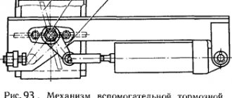
At the end of the expansion cam shaft there is a worm-type adjusting lever (Fig. 1) connected to the brake chamber rod.
By turning worm 3 by the hexagonal head of the axle with a wrench, you can turn the expansion fist and, consequently, spread the brake pads, thereby reducing the gap between them and the drum.
To rotate the axis, plate 7 must be released and moved upward.
On vehicles, an adjustment lever with a built-in automatic regulator can be installed (Fig. 2).
To prevent lubricant from entering the brake mechanisms, rubber O-rings are installed in the brackets of the front and rear brake expansion knuckles.
The brake chambers are diaphragm, designed to activate the brake mechanisms of the front wheels of the car when the service brake system is turned on.
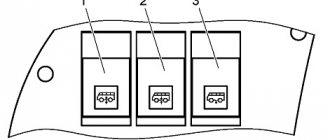
Brake chambers with spring energy accumulators (Fig. 3) are designed to activate the brake mechanisms of the wheels of the rear and middle axles when the service, parking and spare brake systems are engaged.
When the service brake system is turned on, the brake mechanisms are actuated by the rods of 10 diaphragm brake chambers, the design and principle of operation of which is practically no different from the front brake chambers (inlet 11).
When the parking brake system is turned on, compressed air is released from the cavity under the piston 6, which, under the action of the power spring 7, moves down and moves the pusher 4, the latter, through the thrust bearing 9, acts on the diaphragm 3 and the rod 10 of the brake chamber, resulting in the car braking.
When the parking brake system is turned off, compressed air is supplied under the piston 6 through the inlet 12, which, together with the pusher, moves upward, compressing the spring and allowing the brake chamber rod to return to its original position under the action of the return spring 1.
When braking by the reserve system, air from the cylinders of the energy accumulators is partially released to the extent of the required braking efficiency of the vehicle, which corresponds to the intermediate positions of the control valve handle. Thus, the braking efficiency depends on the angle of rotation of the crane handle.
Gearbox MAZ 4370
The truck was produced with three different transmissions:
- ZIL-695D (Saransk, Russia) - the gearbox was installed in tandem with the D-245 engine on MAZ 437040;
- SAAZ-3206 - gearboxes were paired with improved D-245 engines (Euro-2 and Euro-2) on modifications MAZ 43704 and MAZ 437043, respectively;
- ZF S5-42 (Spain) - gearboxes were installed on modifications of the MAZ 437030, equipped with Deuts.
All available transmissions are five-speed manual. By design they are dry, single-disc friction. The clutch disc size can be 340 or 360 mm in diameter. A bevel gearbox and a cross-axle differential with locking are installed on the driving rear axle.
In addition to native gearboxes, which are not particularly reliable, Chinese-assembled gearboxes are offered for the MAZ 4370, for example 6J60T and 6J70T. They are designed by the American company Eaton and manufactured in China under contract. Unlike native gearboxes, Chinese ones have six speeds.
Clutch release drive
MAZ 4370 gear shift diagram
The gearbox is controlled using a lever according to the following scheme:
Gear shift diagram for MAZ-4370
MAZ 4370 gearbox control drive (diagram)
Diagram of the gearbox control drive on the MAZ-4370
- Lever arm
- Sealing case
- Plate
- Bolt
- Traction
- Bolt
- Traction
- Lever arm
- Fork
- Sleeve
- Spring
- Earring
- screw
- Shank
- Tip
- Traction
- Switching mechanism
- Ball
How to spread the pads on grease
Maintenance and adjustment of brakes of MAZ-64227, MA3-54322 vehicles
Adjusting the brake mechanisms. The free play of the brake pedal is determined by the design of the brake valve and is 25–40 mm. The pedal free play cannot be adjusted during operation. In adjusted brakes, the gap between the linings and the drum is 0.4 mm, which corresponds to the stroke of the brake chamber rods within the range of 25-40 mm. When the rod stroke increases to 45 mm, the brakes must be adjusted. In this case, the difference in the stroke of the brake chamber rods on each axle should not exceed 8 mm.
Adjustment of the brake mechanisms must be done in the following order:
jack up the wheel; turn the worm 3 (see Fig. 92) of the adjusting lever of the expansion knuckle until the drum catches when the wheel rotates, having first loosened the bolt 6 and moved the locking plate 5 upward from the worm;
turn the worm in the opposite direction by 1/2-1/3 of a turn, which corresponds to the stroke of the rod within 25-40 mm and lock the worm axis by sliding the plate to its original position and securing it with a bolt.
Maintenance of pneumatic brake drive
During TO-1, the tension of the compressor drive belt is checked. The belt should be tensioned so that when pressed in the middle of a short branch of the belt with a force of 3 kgf, its deflection is equal to 5-8 mm. If the belt bends more or less than the specified amount, its tension is adjusted, since reduced or increased tension can lead to premature wear of the belt. The adjustment procedure is as follows; loosen the nut securing the tensioner pulley axis and the nut of the tensioner bolt;
by rotating the tensioner bolt clockwise, adjust the belt tension;
tighten the nuts securing the tensioner bolt axle.
The overall oil consumption of the compressor depends on the reliability of the seal of the oil supply channel in the rear cover of the compressor, so you need to periodically remove the back cover and check the reliability of the seal. If necessary, the parts of the sealing device are washed in kerosene and thoroughly cleaned of coked oil.
After 40-50 thousand kilometers, the compressor head is removed, the pistons, valves, seats, springs and air channels are cleaned of carbon deposits, the suction hose is removed and blown out, while simultaneously checking the tightness of the valves. Worn valves that do not provide tightness are ground to the seats, and if this fails, they are replaced with new ones. New valves should also be ground in. If knocking noises appear in the compressor as a result of an increase in the gap between the connecting rod bearings and the crankshaft journals, the compressor connecting rod bearings are replaced.
If the compressor does not provide the required pressure in the system, first of all check the condition of the pipelines and their connections, as well as the tightness of the valves and pressure regulator. Check the tightness by ear or, if the air leak is small, using soapy water. Leaking parts are replaced.
How the brakes work
At the moment of forward movement of the T-25 tractor, the pulley rotates clockwise. At the moment of braking, the tape begins to touch it, and the rear brake lever is thrown back by friction until it rests against the adjusting bolt.
The brakes are tightened by moving the end of the band and the front lever. In this case, a friction force arises (between the lining and the pulley) which moves the belt towards the puffs, with minimal force on the brake pedal.
In reverse: the pulley rotates counterclockwise. Then the lever is pressed against the stop and the front end of the belt becomes the forward end and braking occurs using the rear brake lever.
At the end of braking, the springs return the band and pedal to their original position.
Important! In this case, the pedal should return to its original position without jamming.
If this happens, then you need to loosen the fastening bolts and turn the covers within the permissible gap.
If oil gets on the brake band linings, the effectiveness of the brakes is greatly reduced; for this, the ends of the shaft are sealed with self-moving oil seals.
How to spread the pads on grease
MAZ-152. Brake System Maintenance
4.8.7.1 care and adjustment of brake mechanisms
When carrying out maintenance, lubricate the bearings of the expansion knuckles, the axes of the brake pads and the adjusting levers with CV joint grease-4 in accordance with the instructions given in the Chemical Card.
ADJUSTING THE STROKE OF BRAKE CHAMBERS
In adjusted brakes, the full stroke of the brake chamber rods should be within 38.44 mm. When increasing the stroke of the rods, as well as when replacing the adjusting lever, it is necessary to adjust the stroke of the brake chamber rods. The difference in the stroke of the brake chamber rods on one axis should not exceed 5 mm. The adjustment is made as follows:
— install the adjusting lever (Fig. 4.8.5) on the expansion cam shaft so that the distance from the brake chamber fork to the hole in the lever body is 20-80 mm. The lever should be positioned with the plug 13 forward along the brake chamber rod during braking, and with the hexagonal end of the worm shaft 14 facing the brake chamber;
— by rotating the hexagonal end of the worm shaft 14 counterclockwise (you should feel the clicks of the reverse clutch), align the holes of the chamber rod fork and the lever body, connect the lever to the fork with your finger and secure it with a cotter pin. The expansion cam shaft must remain in its original position under the action of the tension spring of the pads;
— turn the leash together with the ear of the control drive 5 until it stops (in the direction of rotation of the lever when braking) and secure it in this position;
— press the brake pedal all the way, supplying compressed air into the brake chamber at a pressure of 0.6 MPa (6 kgf/cm2), no less. In this case, the stroke of the rod should be within 25.35 mm. If the stroke of the brake chamber rod exceeds 35 mm, it is necessary to make an adjustment by turning the hex head of the worm 14 counterclockwise.
To remove the lever (to increase the stroke of the brake chamber rod or to facilitate removal of the brake drum), it is necessary to unscrew plug 6, use a screwdriver to remove the movable coupling half 11 from engagement with the teeth of the fixed coupling half, and, rotating the worm shaft 14 by the adjusting hexagon clockwise, remove the lever to the required distance.
MAZ-152. CONDITION CONTROL AND REPLACEMENT OF BRAKE LININGS
The design of the brake mechanisms provides for an easily removable brake drum and the ability to visually determine the condition of the brake linings through inspection holes in the brake panels 25 (see Fig. 4.3.1). If the lining is worn down to the limiting shoulder of the lining (shoulder height 5 mm), or if the residual thickness of the lining material is less than 1 mm to the rivet heads, they must be replaced.
To replace worn linings you must:
— remove the wheel, unscrew the brake drum mounting bolts;
— screw two dismantling bolts (M16 thread) into the dismantling threaded holes of the brake drum
and dismantle the drum by uniformly screwing in the bolts;
Figure 4.8.5 — Adjustment lever: 1 — pusher; 2 - gear; 3, 7 - sealing ring; 4 - screw; 5 - control drive; 6 - plug; 8 - control valve; 9 — body; 10 — oiler; 11 - movable coupling half; 12 - spring; 13 - plug; 14 - worm shaft
— remove tension springs 12;
— Unscrew the bolt and remove the locking plate of the pad axles;
— knock out the axles of the pads towards the brake shield and remove the pads;
— replace worn linings with new ones, and install the pads in the reverse order of removal.
After riveting the linings, they are grooved to speed up running-in.
After installing the brake pads, lubricate axle 27 with CV joint-4 grease until grease appears from valve 24.
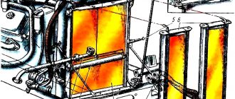
EVERYTHING about the energy accumulator
If you mix up the tubes on the energy generator during installation, it will always be in a inhibited state, i.e. the rod will be extended and will not “go” inward, regardless of whether you removed the handbrake (pressed the brake pedal) or not
How does a brake chamber with an energy accumulator work?
in this video
How to check the energy accumulator
Recently, it seems, I wrote to someone about this. I will write again, for the last time.
1) If you check the energy accumulator on a single vehicle or tractor:
— put the car on the handbrake;
— unscrew the brake pipe from the power supply (under No. 1 in the figure)
*** Note! A couple of times, I don’t remember on which cars, I saw that the exits were located the other way around!
— remove from the handbrake;
— if the energy accumulator is working properly, then no air should come out of the thread from which the tube is unscrewed;
— then we disconnect tube No. 2 (left figure) and check the air leak on the removed handbrake from the energy accumulator side // or check the leak on the removed handbrake through hole No. 2 (right figure) for installing the brake release bolt;
— if the energy accumulator is working properly, then there should be no air leakage.
2) If you are checking energy accumulators on a trailer (semi-trailer)
— fully inflate the trailer;
— remove the road train from the handbrake;
— unscrew the brake pipe from the power supply (under No. 1 in the figure)
— if the energy accumulator is working properly, then no air should come out of the thread from which the tube is unscrewed;
— then we disconnect tube No. 2 (left figure) and check the air leak on the removed handbrake from the energy accumulator side // or check the leak on the removed handbrake through hole No. 2 (right figure) for installing the brake release bolt;
— if the energy accumulator is working properly, then there should be no air leakage.
The design of the MAZ brake system and how to troubleshoot it
The MAZ (TS) brake system serves to ensure safety when the truck is moving and secure it in the parking lot. Structurally, it is made in the form of four independent systems: working, parking, spare and auxiliary. In normal driving mode, a working vehicle is used, but if it fails or emergency braking is applied, all brakes are activated.
Maintenance
The brake drum for MAZ 4370 is included in the device:
- Parking system;
- Working system;
- Spare system;
- Assistive system.
As a rule, the part is very durable. Special production technologies can increase the service life of truck suspension parts.
However, no matter how strong the unit is, remember that the condition of the MAZ brake drum directly affects the safety of movement.
The spare part requires regular maintenance and care. It is necessary to monitor the condition of the part and carry out timely repairs.
Device
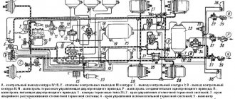
The brake system circuit is designed on the principle of independent influence on the drive mechanisms of the wheels of the front and rear axles. The pneumatic vehicle used on MAZ vehicles consists of the following elements:
- compressor;
- compressed air tanks (receivers);
- pneumatic pipelines and control devices;
- brake mechanisms.
The vehicle can be equipped with a single or double cylinder compressor. The latter is used on tractors (road trains).
Compressed air is supplied through a pneumatic line to the receivers. Depending on the model, the vehicle can use 3 or 4 air cylinders of different capacities. Each pair of wheels (axle) has its own receiver: front and middle - 40 liters each, rear - 20 liters. The parking system is equipped with a separate 20-liter cylinder.
Malfunctions
When operating a vehicle, the following breakdowns may occur:
- low braking efficiency;
- uneven braking of the wheels of the right and left sides;
- jamming of service or parking brakes (brake jam);
- increased travel of the parking brake handle.
An increase in braking distance can occur due to a large gap between the pads and the brake drum (TB), due to wear of the pads or insufficient output of the rod at low pressure in the pneumatic system. If such a malfunction appears after repairs associated with replacing the pads, then there is a high probability of oiling of the friction material or the inner surface of the brake pad.
In most cases, a car skidding during braking occurs due to a large difference in the strokes of the brake rods installed on one axis or the shaft getting stuck in the expansion cam bushings in the brake pad block.
Slow release most often occurs due to a broken or stuck return spring in the brake cylinder. The cause of such a defect may also be incorrect adjustment of the brake pedal. Therefore, the brake valve lever does not reach the stop. Due to the breakdown of the brake pad tension springs, spontaneous braking may occur, and a characteristic knocking sound in the wheel will be heard when driving.
When driving a truck with a trailer, there may be a delay in the latter's braking. This is due to incorrect installation of the adjusting ring in the brake valve. The same failure is typical for a stuck piston in the trailer air distributor.
It must be remembered that a breakdown in the steering will only lead to a loss of control of the car, and a vehicle failure will lead to the impossibility of stopping it, which will inevitably end in an accident.
How to solve a problem
Naturally, motorists are interested in what to do if the handbrake is jammed, and how this could turn out.
There are 2 main situations when there are problems with the parking brake:
- the car does not want to be released from the handbrake;
- The car cannot be put on the handbrake.
It would be fair to call the first situation jamming. We’ll tell you more about it.
Since the handbrake does not release and continues to block the wheels, it is important to first exclude the option of freezing. If it is a warm season and there were no frosts at night or while the machine was idle, the jamming occurred precisely for mechanical reasons. Some kind of breakdown occurred.
There are several potential culprits and solutions to the problem here.
- Handbrake cable jammed or broken. It needs to be inspected and adjusted. If the defect is serious, it will have to be replaced.
- Jamming due to rust formation. Relevant for machines that have been idle for a long time and have not been used. At the same time, the car was stored in a humid environment. Rust has stuck to the pads, caliper or brake disc (drum). This will require dismantling, cleaning or replacing elements.
- The pad linings became soggy, which caused them to stick to the drums. You will probably have to solve the problem by replacing the elements.
Some motorists advise trying to move forward and backward, tap the problem unit with a hammer, insert a pry bar into the gap between the jammed block, and manually try to loosen it.
In reality, such actions can lead to serious consequences. It is better to carefully examine the condition of the handbrake, determine the cause of the jamming, and carefully eliminate it by sequential dismantling, or by contacting a car service.
If the problem is related to the fact that the block is frozen, which can be determined by the presence of an ice crust and indirect signs such as driving through puddles and freezing temperatures, it is much easier to solve.
How to remove a brake drum
During vehicle operation, both the brake pad linings and the inner surface of the drum wear out. As a result, braking efficiency is lost. In this case, it is necessary to dismantle the drum and replace the pads. The dismantling work is not difficult, but it will require some physical effort, because... the parts are heavy.
To remove the brake drum, do the following:
- install the machine on a flat surface and secure it against possible movement;
- jack up the wheel;
- unscrew the nuts and remove it;
- screw 3 M10 bolts into the holes on the drum cover and press it out;
- remove the part from the hub.
It must be remembered that the TB is made of cast iron, so you need to use a hammer to remove it with great care.
Replacing linings
Brake pads consist of two parts: a metal body and a friction lining. Previously, about 40 years ago, the linings were made of asbestos-containing material, which was installed on a metal part using rivets. The service life of such parts was small and amounted to 40-50 thousand km. Today, new friction materials are used that can last 180-200 thousand km without replacement. Therefore, there is no point in replacing brake linings, and the pads are replaced as a set.
After removing the drum to dismantle the elements, you must perform the following steps:
- remove the spring that tightens the pads;
- dismantle the cups with springs that press the parts to the protective casing;
- remove the pads from their seats.
If you decide to replace only the friction linings, then in addition to the listed actions you must perform the following:
- dismantling the remaining friction material;
- cleaning the surface of the part;
- installation of new linings;
- processing on a lathe to the required size.
The installed material must have a thickness of at least 7 mm, with a margin of 3.5 mm to the rivet head. The gap between the friction material and the pad body is allowed no more than 0.1 mm. Such work can be performed without special devices using a bench vice in compliance with the required dimensions and tolerances.
Chassis and suspension
The chassis and suspension of the MAZ 4370 deserve praise. It is largely due to the excellent quality of Zubrenok’s design and suspension assembly that it has become so widely used. With careful operation without major repairs, the chassis will last 250 thousand km, but even then, after replacing worn out elements, it will work for hundreds of thousands of kilometers without any problems.
The front spring of the MAZ 4370 consists of several sheets. The front suspension is equipped with hydraulic shock absorbers with stabilizers. The rear spring is semi-elliptical.
In general, this design gives a rough ride, but is easy and simple to repair and does not require special maintenance.
Wheel sizes range from 17 to 20”. The suitable tire size is 235/75R17.5.
History of creation
The Minsk Automobile Plant developed the concept of the future MAZ 4370 in cooperation with the Gorky Automobile Plant. The first conceptual low-frame, medium-tonnage trucks were designed by enterprise engineers in the 90s. But after the collapse of the USSR, MAZ decided to refuse cooperation with the Russian automobile plant, since for a number of reasons it became difficult to interact with representatives of another state. In this regard, Minsk decided to stop supplies for other trucks, in particular for MAZ 5336, cabs produced by GAZ.
Without abandoning the idea of creating a medium-tonnage truck, Mazov engineers decided to take the MAN L 2000, assembled in Germany, as a prototype. Having adjusted a number of functions and increased the carrying capacity, the Minsk Automobile Plant created the MAZ 4370 Zubrenok exactly in the form in which it rolled off the assembly line in 1999.
Entering the Russian market
At the time the new product appeared on the Russian truck market, there were two main competitors in this class - GAZ 3310 and ZIL 5301. The Belarusian medium-duty truck outperformed them in several ways. Firstly, the cabin was more spacious and comfortable. Secondly, the carrying capacity of the new product was higher, which was perhaps the most powerful argument in its favor, all other things being equal. For a long time, the MAZ 4370 truck simply had no competitors in the domestic car market. Zubrenok is in high demand to this day.
In 2007, the Kama Automobile Plant launched onto the market a direct competitor to the Zubrenok MAZ 4370 - KamAZ 4308, which was popularly nicknamed “Kamazenok”. Not wanting to give up their position, the automaker worked on modernizing their truck. In 2010, the manufacturer introduced the second generation of Zubrenok. The updated truck received the MAZ 4371 index. It has a redesigned cabin, which has become even more comfortable to meet the requirements of the time. Also, the MAZ 4371 Zubrenok-2 was equipped with more environmentally friendly diesel engines.
Previously, we wrote about the technical characteristics of the KS-5473 Dnepr truck crane and the features of its operation.
Source
Adjustment
In serviceable and adjusted brakes, the gap between the lining and the inner surface of the drum should not exceed 0.4 mm. This corresponds to the movement of the TC rod by 25-40 mm. If this value increases to 45 mm or more, then adjustment of the brakes is necessary. Most drivers prefer to do this work with their own hands.
Adjustment work involves sequentially performing the following actions:
- placing the axle on a jack;
- releasing the worm screw of the adjusting lever from the locking plate;
- turning it until the rotating wheel begins to brake;
- rotation of the worm in the opposite direction by 1/3 of a turn, which will correspond to a rod stroke of 25-40 mm.
- return the stopper to its original position.
It must be remembered that the difference in stroke of the TC rod on one axis should not be more than 8 mm. Serviceable brake systems will ensure safe movement and parking of the car.