Manual MAZ 203 203065-0000020 RE (2016) - page 7
2.2.5
MAZ-203. Buttons and switches
On the left switch panel
(Fig. 2.5) switches and switches for operating modes of electrical equipment are located:
2 - switch for the body tilt control system and return of the suspension to the working position. When you press the lower arm of the key, the right side of the body is lowered; during the lowering process, the symbol C of the body tilt system operation flashes on the LCD display. After reaching the bottom position, the symbol lights up without blinking.
The mode is used for the convenience of boarding and disembarking passengers. Returning to the normal position is carried out by pressing the upper arm of the key once.
ATTENTION! MODE IS INTENDED ONLY FOR THE CONVENIENCE OF BOARDING AND DISCHARGING PASSENGERS. DO NOT DRIVE WITH THE TILTING SYSTEM ENABLED!
3 - PZD switch. Three-position switch (in position I, only the heater circulation pump is turned on, in position II, the liquid heater is turned on).
ATTENTION! TURN ON THE HEATING WATER ONLY WHEN AT LEAST ONE OF THE HEATING SYSTEM CAP OR ENGINE WARMING CAP IS OPEN.
- When the coolant reaches operating temperature (about 78 °C), the heating is automatically turned off, but the heater circulation pump continues to operate. If the coolant temperature drops to +65 °C, the heating is turned on again;
- – air circulation switch. When the upper arm of the key is pressed, air entering the front heater is taken from the driver's cabin (recirculation mode). Turn on the air intake from the passenger compartment only when necessary (driving through areas with high dust levels or an unpleasant odor). When the lower arm of the button is pressed, the front heater flap provides air intake from outside and the warning lamp lights up.
- – side window heating switch. When you press the button, the heated side window is turned on. Heating can only be turned on when the engine is running; 6
– mirror heating switch. When you press the button, the heated exterior mirrors are turned on. Heating can only be turned on when the engine is running.
Gatele;
7 – switch for cabin heater fans. Turn on fans if necessary to increase the efficiency of interior heating;
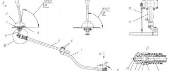
Figure 2.5 - Left switch panel: 2 - body tilt control system switch; 3 — switch PZD; 4 — air circulation switch; 5 — side window heating switch; 6 — mirror heating switch; 7 — switch for cabin heater fans; 8 — switch for roof fans of the passenger compartment; 9 — interior lighting switch; 10 — switch-switch for the operation of the roof fan of the driver’s cabin; 11 — driver’s workplace lighting switch; 12* — driver’s workplace heater switch; 13* — passenger compartment heating switch; 14 — retarder switch; 15 — control lamp for air intake from outside the bus; 16 - switch-switch for operating modes of the heater fan of the driver's workplace * - for buses with electric valves of the heating system
8 — switch for roof fans of the passenger compartment. When the lower arm of the switch is pressed, the fans operate in fresh air supply mode, and when the upper arm of the key is pressed, in exhaust mode. The lower covers of the roof fans open automatically after 20…30 seconds. after turning on the fans;
9 — interior lighting switch. Dim lighting (middle position of the switch key) can be turned on both when the engine is running and when the engine is stopped. Bright lighting (key pressed from below) can only be turned on when the engine is running;
10 - switch-switch for the operation of the roof fan of the driver's cabin. When you press the lower arm of the key, the fan switches on to the external air supply mode; when you press the upper arm, it switches to the air exhaust mode from the workplace. To turn off the fan, set the switch to the middle position;
11 — driver’s workplace lighting switch. Turns on the light above the driver's seat;
12 — driver’s workplace heater switch. Turns on the heating of the driver's workplace;
13 — passenger compartment heating switch. Turns on the heating of the passenger compartment.
14 — GMT retarder switch. When you press the lower arm of the key, the GMF function in retarder mode is disabled. When the upper arm is pressed, the GMF function is activated in the retarder mode.
Disable the retarder function when driving on slippery roads.
15 - control lamp for air intake from outside the bus. Lights up when air is taken in by the front heater from outside the bus;
16 — switch-switch of operating modes of the heater fan of the driver’s workplace. In the extreme left position, the heater fan is turned off. When turning the knob clockwise, the blowing intensity increases in steps.
On the side surface of the left switch panel there is the main light switch 11 (Fig. 2.1). When you turn the switch knob to the right to the first position, the side lights turn on. When turning to position II, the low or high beam is turned on depending on the position of the left steering column switch. The fog lights can be turned on by pulling the knob to the first position only when the knob is turned (with the side lights or headlights on). When the handle is pulled to position II, the rear fog lights are additionally turned on.
When the high beam switch is turned on, the fog lights are automatically turned off;
Body position control keys (for buses with electronically controlled suspension ELS5)
The body position control on buses with electronically controlled suspension is carried out using keys installed on the left panel of switches (Fig. 2.5.1).
1
– key for raising/lowering the bus body. When you press the lower arm of the key, the bus body is smoothly lowered. When the upper arm of the key is pressed, the body is raised smoothly, and when the lower arm is pressed, the body is lowered. In the process of changing the body position, the symbol for deviation of the body position from normal and the symbol for raising or lowering the body light up. When the desired level is reached, release the key. Sim-
the ox goes out. If the body has reached the maximum upper or lower level, the symbol goes out even if the key is held down. The symbol always lights up when the body position deviates from normal.
To return the body to its normal position, you must press the lower arm of key 2 once. When the normal position of the body is reached, the symbol goes out. When the body is in a raised or lowered position, you can move at a speed of no more than 15 km/h; when a speed reaches 15 km/h, the suspension automatically returns to its normal position. If the electronic suspension system malfunctions, the symbol lights up
and indicator 3 lights up constantly (Fig. 2.4);
Attention! BODY LIFT MODE IS INTENDED ONLY FOR SHORT-TERM USE WHEN OVERCOMING OBSTACLES at a speed of no more than 10 km/h.
- –
body return key to normal position. To return the body to its normal position, you must press the lower arm of the button once. When the body reaches its normal position, the symbol goes out.
- –
body tilt activation key. When you press the lower arm of the key, the right side of the body is lowered; during the lowering process, the symbol for the operation of the body tilt system lights up on the LCD display. When the desired inclination is achieved, release the key.
Return to the normal position is carried out by pressing key 2 once.
203065-0000020 RE
Attention! MODE IS INTENDED ONLY FOR THE CONVENIENCE OF BOARDING AND DISCHARGING PASSENGERS. MOVEMENT IS NOT ALLOWED WITH THE BODY Tilting System ENABLED!
If you start driving while the body tilt system is on, then when a speed of 7 km/h is reached, the body automatically returns to its normal position.
On the right switch panel
(Fig. 2.6) there are switches and mode switches for electrical equipment, which are often used by the driver when operating the bus: 1 – button for turning on the hazard warning lights with a warning lamp. The hazard warning lights are turned on by pressing the button (the button is pressed), and the indicator lamp built into the button flashes. Switching off is done by pressing the button again
(the button is recessed);
2
– button for turning on the stopping brake. By pressing the button to a fixed recessed position, the stopping brake is activated. At the same time, the parking brake symbol lights up. Switching off is done by pressing the button again. Apply the stopping brake only after the bus has come to a complete stop.
3, 5, 8, 13 – door opening buttons. When you press the button, the corresponding door opens, at the same time turning on
The stopping brake is released and the indicator lamp built into the button lights up;
4, 6, 9, 10 – door closing buttons. When you press the button, the corresponding door closes. After the door is completely closed, the indicator lamp built into the button goes out. After all doors are completely closed, the stopping brake is released;
7 – GMP control panel:
“D” – forward movement;
“N” – neutral;
“R” – reverse;
“1” – first gear (gear shift limitation – no higher than first gear);
“2” – second gear (gear shift limitation – no higher than second gear);
“3” – third gear (gear shift limit – no higher than third gear).
- – button for general closing of all doors of the passenger compartment;
- – button for general opening of all passenger compartment doors;
Attention! DO NOT HOLD THE DOOR CONTROL BUTTONS PUSHED
14 – button for automatic announcement of stops. When you press the button, the voice informant announces the current and next stop.
Figure 2.5.1 — ELS5 electronic suspension control keys: 1 — body lift/lower switch; 2 — key to return the body to its normal position; 3 — body tilt switch
Figure 2.6 - Right panel of switches: 1 - button for turning on the hazard warning lights; 2 — stop brake button; 3 — button for opening the driver’s cab door; 4 — button for closing the driver’s cab door; 5, 8, 13 — door opening buttons; 6, 9, 10 — door closing buttons; 7 — GMP control panel; 11 — button for closing all interior doors; 12 — button for opening all interior doors; 14 — automatic stop announcement button
MAZ-203.
Buttons and switches of the additional panel
Figure 2.7 - Additional panel: 1 - button for turning on the additional ACSS lubrication cycle; 2 - emergency switch; 3 — diagnostic connector of the on-board control system; 4 — parking brake handle; 5 - 12 V socket; 6 — air heater switch-regulator; 7 — body lift control switch (optional) 8 — emergency parking brake release toggle switch
An additional panel (Fig. 2.7) is installed to the left of the driver. The following controls are located on it:
1 — button for turning on the additional lubrication cycle of the automatic centralized lubrication system (ACLS) with a warning lamp. To activate an additional lubrication cycle, hold the button pressed for 2 s; when the lubrication pump is turned on, the indicator lamp built into the button lights up. The warning lamp also lights up when the lubrication process is automatically started. The button indicator lamp also performs diagnostic functions: flashing or continuous lighting of the lamp indicates a system malfunction. Since the system operates in automatic mode, use the button only in exceptional cases. To prevent damage to the ACSS when the lamp flashes or is constantly lit, it is advisable to disconnect the power connector of the central lubrication pump before eliminating the malfunction;
2 - emergency switch. When you press the switch button, the engine stops and the circuit that is switched off by the contactor opens. Along with this, the emergency light alarm and emergency lighting of the passenger compartment are turned on.
WARNING! WHEN PRESSING THE BUTTON ALSO DISCONNECTS THE DOOR CONTROL DRIVE. DOORS CAN ONLY BE OPENED USING EMERGENCY CRANES.
3 — diagnostic connector for the on-board control system “OBD” (installed on buses that meet Euro-4, Euro-5 environmental standards). The connector is intended for connecting environmental control devices or diagnostic devices.
operating ticks of systems included in the bus CAN network;
4 — parking brake handle;
5 - 12 V socket. Designed to connect any consumers with a voltage of 12 V and a power of no more than 100 W;
6 — air heater switch-regulator. When turning the knob clockwise, the air heater of the driver's workplace is turned on. Using the regulator, the temperature of the heated space is smoothly controlled;
7 — body lift control switch (bus equipped with a pneumatically controlled body lift system). When turning the switch knob clockwise, the body rises until the shock absorbers are fully stretched (about 100 mm), at the same time the body lift activation symbol lights up.
ATTENTION! THE MODE IS INTENDED ONLY FOR SHORT-TERM USE WHEN CROSSING OVER RAILS, OBSTACLES, OR WHEN INSTALLING THE BUS ON AN OVERSTAND OR INSPECTION PIT!
8 — toggle switch for emergency release of the stopping brake. The toggle switch is located behind a sealed cover. Provides unlocking of the stopping brake for bus movement in case of emergency condition of the door drives.
Warning buzzer
An intermittent buzzer sounds in the following cases:
- if the oil pressure in the engine lubrication system is less than 0.06 MPa (0.6 kgf/cm2), the emergency oil pressure symbol lights up at the same time. Stop the engine immediately, start the engine only after eliminating the malfunction;
- If the engine oil level is below the permissible level, the emergency oil level symbol lights up at the same time. Immediately stop the engine and add oil to the normal level;
- If the coolant level is below the permissible level, the emergency coolant level symbol lights up at the same time. Immediately stop the engine and add coolant to the normal level;
- if the coolant temperature
above the maximum permissible (about 105 °C),
Attention! mode Intended
ONLY FOR SHORT TEMPORARY USE WHEN CROSSING RAILS, OBSTACLES, WHEN INSTALLING THE BUS ON AN OVERSTATE OR INSPECTION PIT!
8 – toggle switch for emergency release of the stopping brake. The toggle switch is located behind a sealed cover. Provides unlocking of the stopping brake for bus movement in case of emergency condition of the door drives.
At the same time, the coolant temperature alarm symbol lights up. Reduce the load on the engine, check and, if necessary, clean the surface of the radiator of the cooling system;
- If the oil level in the power steering tank is below the permissible level, the emergency oil level symbol in the power steering tank lights up at the same time. Check the tightness of the power steering system, add oil to the required level (driving with precautions is allowed to a service station);
- When the air filter is clogged, the air filter clogged symbol lights up at the same time. Carry out maintenance of the air filter (driving to the service station is allowed at engine speeds at which the symbol goes out and the buzzer goes off).
A constant signal is given:
- If the “Stop Request” button is pressed in the passenger compartment, the symbol lights up at the same time;
- If the gangway supply button is pressed outside or inside the bus, the gangway demand symbol lights up at the same time.
Parking brake
The parking brake valve handle 4 (Fig. 2.7) is located to the left of the driver on the additional panel. When the handle is in the forward position, the parking brake is released. To turn it on, you need to move the handle to the rear fixed position, while the parking brake indicator light on the instrument panel flashes. To use the parking brake as a backup, the handle should be moved to any intermediate position (the closer the handle is to the rear position, the higher the braking efficiency). When released, the handle automatically returns to its most forward (uninhibited) position.
When the air pressure in the pneumatic system is below 0.55 MPa (5.5 kgf/cm2), as evidenced by the lighting of the warning lamp, the springs of the energy accumulators hold the parking brake in a locked state. To achieve complete release of the brakes and allow the bus to move, it is necessary to bring the air pressure in the pneumatic system to a value above 0.55 MPa (5.5 kgf/cm2), at which the warning lamp should go out.
In an emergency, brake chambers with energy accumulators can be unlocked mechanically (by unscrewing the bolts on the energy accumulators) or pneumatically (by supplying air from an external source through a fitting located behind the central front panel).
Warning! It is prohibited to leave the Driver's workplace unless the parking brake is on!
Attention! Turn off the parking brake only before starting to move when the pressure in the pneumatic system reaches above 0.55 mPa (5.5 kgf/cm2).
Stop Brake
The stopping brake is activated by pressing button 2 (Fig. 2.6) and released by pressing the same button again. When the parking brake is applied, the parking brake symbol lights up. It is recommended to use the stopping brake during short stops, as it consumes significantly less air than service brakes. In addition, using a parking brake (rather than a parking brake) at stops extends the service life of spring energy accumulators.
If the hand brake control button is in the brake release position, the parking brake operates automatically according to the following principle:
- the brake is activated if the body tilt system is turned on or for any reason any of the doors begins to open, provided that the bus speed does not exceed 5 km/h;
- The parking brake is released when the tilt system is turned off after all passenger compartment doors are closed.
In an emergency (if doors break, etc.), the stopping brake can be turned off using toggle switch 8 (Fig. 2.7), which is located on the additional instrument panel behind the sealed locking cover.
For the safety of passenger transportation, we strongly recommend that you do not operate buses with a disabled or faulty automatic parking brake system when the passenger compartment doors are open.
Attention! It is prohibited to use the stopping brake when parking the bus in a parking lot, since it is electrically controlled and is disabled when the ignition key is turned to Position “0” or “III”. The stopping brake does not hold the bus on a road with a significant slope of more than 10%, so at stops with a significant slope it is necessary to use the parking brake.
MAZ 642205, 6422A5, 642208, 6422A8, 630303, 6303A3, 630305. Manual - part 1
3
Three-axle tractor with drive to the middle and rear axles and
two-axle with rear axle drive, equipped with a fifth-wheel coupling device and designed for transportation of various cargoes as part of a road train on public roads that allow axial masses specified in the technical specifications.
A three-axle tractor can be equipped with hydraulic equipment
It is suitable for working with specialized and dump semi-trailers.
A three-axle truck and a two-axle truck have
They have a metal platform with folding side and rear sides and are designed for transportation of various cargoes on public roads that allow axial weights specified in the technical specifications.
At the buyer's request, trucks can be supplied
equipped with an awning and in the form of a chassis without a loading platform.
The vehicle is equipped for transporting timber
rials in assortments with lengths from 2.0 to 6.0 m, laid on a special platform installed on the vehicle chassis.
Three-axle dump truck with a metal body, rollover
created using a hydraulic mechanism, designed for transportation of non-metallic construction bulk cargo: sand, gravel, soil, crushed stone, sand-gravel mixture on non-public roads, allowing a maximum weight per trolley of 26 tons. The vehicle is equipped with - dump truck MAZ-551608, MAZ-5516A8 with increased body volume for transporting grain, wood chips and other lightweight bulk cargo.
Cars can be produced with a large or small cabin, body
with a tailgate or bucket type.
Cars can be supplied without a body and tipping mechanisms -
tions for complete set with various equipment.
Tractor vehicles are designed for operation with a semi-trailer,
having connecting dimensions in accordance with GOST 12105-74, a coupling pin of class H50 in accordance with the requirements of UNECE Rules No. 55, pneumatic outlets in accordance with GOST R 50023-92, detachable electrical circuit connections in accordance with GOST 9200-76, the pneumatic drive of the brake system must comply requirements of UNECE Regulation No. 13.
Trucks are designed to be used with a trailer,
having a coupling loop of class D50, providing backlash-free coupling in accordance with the requirements of UNECE Rules No. 55, pneumatic outlets in accordance with GOST R 50023-92, detachable electrical circuit connections in accordance with GOST 9200-76, the pneumatic drive of the brake system must comply with the requirements of the EE Rules KOOH No. 13.