- No dealer extra charges
- Honest price without markups
- Spare parts in stock
- Work guarantee
FIND OUT THE TIME AND COST OF REPAIRS
Call the technician directly and get detailed advice
order a call Do not delay repairs, the equipment must work and generate income for you
Repair of MAZ trucks is one of the main areas of car service. Our specialists have many years of experience and can easily cope with any malfunction. We offer a full range of repair and maintenance services for MAZ trucks.
Our auto service center can offer the following MAZ truck repair services:
- Repair of gearbox, clutch, gearbox;
- Engine repair and diagnostics;
- Brake system repair and other repair work.
Our service center specialists will familiarize you with the full list of work, and will also help you quickly and efficiently fix the breakdown of your truck at any stage. Just call our managers by phone
Prices for repairs of MAZ trucks:
| Name | Price |
| Engine (except Cummins engine) | |
| Engine diagnostics (fault determination) | 1200 |
| Check the compression ratio in the internal combustion engine cylinders (with the removal of injectors) | 3000 |
| Remove and install engine (tractor, dump truck) | 13000 |
| Remove the engine (tractor, dump truck) | 6500 |
| Install the engine (tractor, dump truck) | 6600 |
| Remove and install engine (flatbed, van) | 15000 |
| Remove the engine (onboard, van) | 7400 |
| Install engine (flatbed, van) | 7600 |
| Remove and install engine (hooded vehicle) | 18000 |
| Remove the engine (hooded vehicle) | 8700 |
| Install the engine (hooded car) | 8900 |
| Remove and install attachments | 4700 |
| Remove attachments | 2100 |
| Install attachments | 2600 |
| Disassemble and reassemble the engine | 44000 |
| Disassemble the engine | 21800 |
| Assemble the engine | 21800 |
| Remove and install the right cylinder head (with the expansion tank and intake manifold removed) 1 piece | 2800 |
| Remove and install the left cylinder head (with the expansion tank and intake manifold removed) 1 pc. | 2200 |
| Remove and install cylinder heads - 8 pcs. | 11800 |
| Remove and install cylinder heads - 4 pieces (on one side) | 7100 |
| Replace valve cover gasket 1 pc. | 130 |
| Remove and install valve rocker arms with axles and rods from one head | 170 |
| Tighten the cylinder heads, adjust the thermal clearances in the valves | 1400 |
| Adjust thermal clearances in internal combustion engine valves | 1100 |
| Replace valve stem seals with the cylinder head removed (1 piece) | 650 |
| Remove and install oil sump | 1300 |
| Remove and install the oil pump with oil receiver | 950 |
| Remove and install the liner, piston, pin, connecting rod with liners, piston rings and sealing rings (with the oil sump and cylinder head removed) on one cylinder | 3500 |
| Remove and install the piston, pin, connecting rod with liners, piston rings (with the oil sump and cylinder head removed) for one cylinder | 2400 |
| Replace engine crankshaft | 25600 |
| Replace the connecting rod bearings (with the oil sump and oil pump removed) | 3300 |
| Replace the main bearings (with the oil sump and oil pump removed) | 3700 |
| Remove and install the thrust half-rings (with the starter, oil sump and oil pump removed) | 2200 |
| Replace the rear crankshaft cuff (with the flywheel removed) | 400 |
| Replace the fluid coupling seal (with the fluid coupling removed) | 400 |
| Remove and install the front cylinder block cover (with the radiator removed) | 900 |
| Remove and install the flywheel housing on the removed engine (with the clutch, flywheel, compressor, power steering pump, starter removed) | 2400 |
| Remove and install the flywheel housing directly on the vehicle (with the clutch, flywheel, compressor, power steering pump, starter removed) | 4700 |
| Remove and install the flywheel (with the gearbox and clutch removed) | 1500 |
| Remove and install fluid coupling (with free access) | 3400 |
| Remove and install the water cavity plug | 600 |
| Remove and install fluid coupling switch | 600 |
| Replace crankshaft support bearing | 600 |
| Remove, install intake manifold (side) | 800 |
| Remove and install viscous coupling (with free access) | 1200 |
| Remove and install the solenoid valve for turning on the fan drive fluid coupling | 750 |
| Remove and install oil cooler (liquid-oil heat exchanger) with free access | 2400 |
| Remove and install front power take-off drive | 1200 |
| Disassemble and assemble the front power take-off drive | 1200 |
| Tighten the engine mounts | 350 |
| Remove and install the front engine mounting mount (with the radiator removed) | 1800 |
| Remove and install rear engine mount | 2200 |
| Remove and install the rear engine mounting mount (with the gearbox removed) | 940 |
| Supply system | |
| Diagnosis of fuel system faults | 600 |
| Check the tightness of the fuel system on the vehicle | 800 |
| Adjust the fuel injection advance angle | 470 |
| Remove and install fuel injection pump | 1500 |
| Remove and install the injection pump drive (with free access) | 2500 |
| Replace the cuff of the fuel injection pump drive | 400 |
| Remove and install fuel priming pump | 800 |
| Disassemble and assemble the fuel priming pump | 1000 |
| Remove and install nozzle (1 piece) | 300 |
| Adjust the nozzle operation | 250 |
| Remove and install high pressure pipe | 300 |
| Remove and install the fuel line pipe | 350 |
| Remove and install fuel tank | 1 200 |
| Remove and install fuel tank bracket (1 piece) | 600 |
| Remove and install BOSH injection pump | 3300 |
| Exhaust system | |
| Remove and install muffler | 1200 |
| Remove and install muffler exhaust pipe | 700 |
| Remove and install metal hose | 1300 |
| Remove and install muffler mounting bracket | 700 |
| Remove and install exhaust pipe | 600 |
| Remove and install exhaust manifold (one side) | 1500 |
| Remove and install the exhaust muffler pipe from the turbocharger | 800 |
| Remove and install exhaust pipe clamp | 350 |
| Remove and install metal hose with tee | 1200 |
| Remove and install turbocharger | 2300 |
| Rebuild the turbocharger | 650 |
| Remove and install the oil supply pipe to the turbocharger | 300 |
| Remove and install the oil drain pipe from the turbocharger | 300 |
| Cooling system | |
| Remove and install radiator | 2200 |
| Remove and install radiator with charge air cooler | 3500 |
| Remove and install charge air cooler | 2000 |
| Remove and install the fan casing (with free access) | 250 |
| Remove and install radiator shutters (with free access) | 350 |
| Remove and install the fan impeller (with free access) | 700 |
| Remove and install thermostat | 500 |
| Remove and install water pump | 1800 |
| Disassemble and assemble the water pump | 1300 |
| Remove and install the engine belt roller | 1100 |
| Remove and install the water pipe (hose) | 300 |
| Remove and install water pipes (kit) | 1500 |
| Remove and install belt | 550 |
| Remove and install expansion tank | 600 |
| Remove and install heater radiator | 1200 |
| Remove and install water pump (Euro-2) | 1200 |
| Replace the O-ring of the thermostat box | 1100 |
| Remove, install bypass pipe, replace 2 o-rings | 1100 |
| Remove and install water pipe | 300 |
| Adjust belt tension | 200 |
| Drain and refill coolant | 500 |
| Add coolant | 200 |
| Clutch | |
| Diagnosis of clutch faults | 350 |
| Remove and install clutch (with gearbox removed) | 1200 |
| Adjust clutch | 900 |
| Disassemble and assemble the clutch basket (2-disc clutch) | 2100 |
| Disassemble and assemble the clutch basket (1st disc clutch) | 1000 |
| Remove and install PSU | 700 |
| Disassemble and assemble the PGU | 1700 |
| Remove and install the PSU tube (hose) | 500 |
| Pump up the PGU | 350 |
| Adjust the clutch free play | 350 |
| Adjust the free play of the clutch pedal | 350 |
| Remove and install clutch master cylinder | 800 |
| Disassemble and assemble the clutch master cylinder | 590 |
| Replace release bearing lubrication hose | 250 |
| Replace the release spring of the pedal or clutch fork | 170 |
| Remove and install the clutch release fork (with the gearbox removed) | 350 |
| Replace the clutch fork shaft bushings | 700 |
| Adjustment to the working size of the intermediate clutch disc | 350 |
| Adjustment to the working size of the clutch pressure plate | 350 |
| Remove and install clutch with release bearing (1st disc clutch) | 470 |
| Remove and install clutch with release bearing (2-disc clutch) | 230 |
| Remove, install automatic clutch regulator (ACC) | 170 |
| Re-rivet the driven disk linings | 590 |
| Remove and install the clutch housing (with the gearbox removed) | 1300 |
| Transmission | |
| Diagnosis of gearbox faults on vehicles | 350 |
| Remove and install gearbox (tractor, dump truck) | 8800 |
| Remove gearbox (tractor, dump truck) | 4400 |
| Install gearbox (tractor, dump truck) | 4400 |
| Remove and install gearbox (flatbed, van) | 11500 |
| Remove gearbox (flatbed, van) | 5700 |
| Install gearbox (flatbed, van) | 5700 |
| Remove and install gearbox (on removed engine) | 1600 |
| Remove and install the ZF gearbox range multiplier (on the removed gearbox) | 2700 |
| Remove and install PTO | 1800 |
| Remove and install ZF gearbox | 15000 |
| Remove and install the divider (on the removed gearbox) | 950 |
| Disassemble and assemble gearbox | 9500 |
| Disassemble gearbox | 4800 |
| Assemble CP | 4800 |
| Disassemble, assemble divider | 4200 |
| Disassemble the divider | 2100 |
| Assemble the divider | 2100 |
| Replace the gear shift fork (with the cover removed) | 500 |
| Remove and install the upper gearbox cover | 1100 |
| Remove and install gearshift control mechanism | 650 |
| Replace the cuff of the gearbox input shaft | 950 |
| Replace the cuff of the gearbox secondary shaft | 1200 |
| Remove and install the gearbox input shaft assembly | 1800 |
| Repress the shaft gear (1 piece) | 450 |
| Replace the ball joint of the gearshift mechanism | 1200 |
| Adjust the gear shift mechanism | 950 |
| Replace the release bearing | 350 |
| Adjust the PTO drive | 600 |
| Replace the divider cable | 700 |
| Cardan shafts | |
| Remove and install propeller shaft | 1300 |
| Remove and install the propeller shaft with intermediate support assembly | 1700 |
| Replace the crosspiece on the removed propeller shaft | 800 |
| Remove and install the suspension bearing (with the propeller shaft removed) | 600 |
| Remove and install rear axle | 4800 |
| Remove rear axle | 2400 |
| Install rear axle | 2400 |
| Remove and install rear axle gearbox | 4600 |
| Remove the rear axle gearbox | 2300 |
| Install the rear axle gearbox | 2300 |
| Remove and install the rear axle gearbox (rear axle removed) | 3700 |
| Remove the rear axle gearbox (rear axle removed) | 1800 |
| Install the rear axle gearbox (rear axle removed) | 1800 |
| Disassemble and assemble the rear axle gearbox | 6200 |
| Disassemble the rear axle gearbox | 3100 |
| Assemble the rear axle gearbox | 3100 |
| Gearbox adjustment | 3600 |
| Replace the shank oil seal by removing the propeller shaft | 1100 |
| Stretch the gearbox shank, gearbox | 800 |
| Remove and install the gearbox shank cover | 300 |
| Replace the shank oil seal (with the propeller shaft and shank cover removed) | 300 |
| Remove and install axle shaft | 550 |
| Remove and install rear axle | 7400 |
| Remove rear axle | 3700 |
| Install rear axle | 3700 |
| Remove and install the axle shaft (drive axle with wheel reduction gear) | 700 |
| Bridge average | |
| Remove and install middle bridge | 5400 |
| Remove middle bridge 2700 | |
| Install the middle bridge | 2700 |
| Remove and install the middle axle gearbox | 5100 |
| Remove the middle axle gearbox | 2600 |
| Install the middle axle gearbox | 2600 |
| Remove and install the middle axle gearbox (the middle axle has been removed) | 3700 |
| Remove the middle axle gearbox (the middle axle has been removed) | 1900 |
| Install the middle axle gearbox (the middle axle has been removed) | 1900 |
| Disassemble and assemble the middle axle gearbox (without center differential) | 6200 |
| Disassemble the middle axle gearbox (without center differential) | 3100 |
| Assemble the middle axle gearbox (without center differential) | 3100 |
| Remove and install center differential | 1700 |
| Remove and install the center differential (with the gearbox removed) | 1200 |
| Disassemble and assemble the center differential | 2600 |
| Disassemble the center differential | 1300 |
| Assemble the center differential | 1300 |
| Remove and install middle bridge | 8000 |
| Remove the middle bridge | 4000 |
| Install the middle bridge | 4000 |
| Wheel reducer | |
| Remove and install wheel reducer | 2300 |
| Remove the wheel reducer | 1000 |
| Install the wheel reducer | 1300 |
| Suspension | |
| Rear suspension diagnostics | 350 |
| Front suspension diagnostics | 350 |
| Adjust the axial play in the balancer suspension shoe | 600 |
| Secure the balancer axis | 700 |
| Secure the balancer axle bracket | 600 |
| Remove and install front spring | 2400 |
| Remove and install rear spring 2-axle vehicle | 2700 |
| Remove and install the rear spring of a 3-axle vehicle with the removal of wheels | 4200 |
| Remove and install the rear spring of a 3-axle vehicle (with the wheels removed) | 3500 |
| Repair the spring | 1000 |
| Replace the spring ladder | 900 |
| Replace the spring eye stepladder | 200 |
| Replace the spring eye bolt | 260 |
| Remove and install spring eye and pin | 1400 |
| Repress the spring ear bushing | 120 |
| Remove and install lower reaction rod | 600 |
| Remove and install the upper reaction rod | 1000 |
| Replace the reaction rod joint | 450 |
| Remove and install the reaction rod bracket | 1200 |
| Remove and install shock absorber | 900 |
| Remove and install the balancer shoe with the wheels removed | 4800 |
| Remove and install the balancer shoe (with the wheels removed) | 4000 |
| Remove and install the balancer axis (with the drive axles removed) | 4500 |
| Remove the balancer axle (with the drive axles removed) | 2000 |
| Install the balancer axis (with the drive axles removed) | 2500 |
| Remove and install the balancer suspension bracket | 1200 |
| Repress the balancer shoe bushings | 350 |
| Replace the balancer shoe protective cup | 120 |
| Replace the O-ring of the balancer shoe | 120 |
| Replace the thrust ring of the balancer shoe | 250 |
| Replace the balancer cuff | 300 |
| Grind the balancer shoe bushings | 1200 |
| Front axle | |
| Remove and install front axle | 5200 |
| Remove and install steering rod | 550 |
| Replace the tie rod pin | 300 |
| Eliminate longitudinal thrust play | 120 |
| Remove and install the steering knuckle (with the hub, caliper and pads removed) | 1900 |
| Remove and install the steering knuckle (front axle drive) | 2400 |
| Remove and install the steering knuckle with the brake caliper removed | 2200 |
| Repress the kingpin bushings | 400 |
| Repress the king pin bearing (1 piece) | 120 |
| Unfold the king pin bushings | 650 |
| Replace the tie rod end | 400 |
| Unscrew the tie rod ends | 700 |
| Remove and install steering knuckle arm | 600 |
| Hubs, wheels, tires | 800 |
| Remove and install the front wheel and hub | 1300 |
| Remove and install the wheel with the drive axle hub (without wheel gear) | 2600 |
| Remove and install the wheel with the drive axle hub (with a wheel reducer) | 350 |
| Replace the wheel bearing | 300 |
| Replace the hub cuff | 270 |
| Adjust the hub bearings (with the cover, axle shaft, and gearbox removed) | 600 |
| Remove and install single-slope hub wheel | 700 |
| Remove and install double hub wheel | 150 |
| Replace the wheel stud (with the hub removed) | 800 |
| Steering | |
| Diagnosis of power steering faults | 350 |
| Remove and install the steering mechanism (without preparatory work) | 3800 |
| Disassemble and assemble the steering mechanism | 3600 |
| Remove and install the power cylinder of the hydraulic booster (without preparatory work) | 2300 |
| Disassemble and assemble the power cylinder | 750 |
| Remove and install power steering pump | 750 |
| Disassemble and assemble the power steering pump | 650 |
| Replace the power steering pump hose | 520 |
| Remove and install steering driveshaft | 800 |
| Replace the steering driveshaft crosspiece | 500 |
| Replace the power cylinder bearing | 350 |
| Remove and install steering column | 800 |
| Bleed the steering hydraulic system | 650 |
| Remove and install the steering gear bipod | 700 |
| Wheel alignment | |
| Diagnostics of the steering axle (play in pivot joints, hub bearings, steering rods) | 600 |
| Checking wheel alignment of the 1st steering axle | 1800 |
| Adjusting the wheel toe of the 1st steering axle | 2500 |
| Adjusting the toe-in of wheels of 2 axles | 5000 |
| Wheel toe adjustment (steering axle) | 3500 |
| Adjusting the alignment of the vehicle's steered axles | 1400 |
| Set the steering wheel mark | 1200 |
| Brakes | |
| Diagnosis of brake system faults | 600 |
| Diagnostics of faults in the pneumatic brake system | 600 |
| Remove and install compressor | 2400 |
| Disassemble and assemble the compressor | 3500 |
| Replace the compressor crankshaft oil seal (with the compressor removed) | 300 |
| Remove and install energy accumulator | 650 |
| Remove and install brake chamber | 500 |
| Remove and install main brake valve | 1200 |
| Replace the air tube, brake hose | 350 |
| Remove and install pressure regulator, pneumatic valve or tap, gearbox air distributor, modulator (1 piece) | 900 |
| Disassemble and assemble the brake chamber | 350 |
| Disassemble and assemble the pressure regulator, pneumatic valve or tap, gearbox air distributor | 600 |
| Pneumatic system repair (according to actual time spent) | 0 |
| Remove and install brake pads (with the brake drum removed) | 360 |
| Remove and install the brake drum (with the wheel removed) | 300 |
| Remove and install the expansion knuckle (with the brake pads removed) | 450 |
| Remove and install the adjustment lever | 300 |
| Remove and install brake caliper | 850 |
| Replace the expansion knuckle bushings (with the expansion knuckle removed) | 600 |
| Re-rivet brake pad linings (1 pair) | 600 |
| Adjust the brakes on the vehicle | 700 |
| Adjust the brakes on the 1st wheel | 200 |
| Grind the brake disc | 1200 |
* Prices on the website are for informational purposes only, please contact our managers by phone
We work with MAZ trucks of the following models:
- Tractor units: 643019-1420-020, 643019-1420-010, 447131,6430 A5, 6430 A8,6430 A9, 6430, 5440, 5440 A3, 5440 A5, 5440 A8, 5440 A9, 5433
- Onboard: 6312 A5, 6312 A8, 6312 A9, 6310, 5340 A8, 5340 A5, 5340 19, 5340 A3, 4371, 4370
- All-wheel drive: 6517, 6425, 6317 (05), 6317 (08), 6317 (09), 6425 (05), 6425 (08), 5309
- Dump trucks: 4581Р2-420-020, 6501В9-420-031, 6501В9-420-000, 6501 А3, 6516, 6501, 5551 А5, 5551 (45), 5551, 5516 А8, 5516, 4570
- Special equipment: Concrete pump (693269), garbage truck (6902B5), dump truck (650108)
- Chassis: 6516, 6312, 6310, 6303, 5516, 5340, 5337, 5336, 4570, 4380, 4371, 4370
Downloading a file
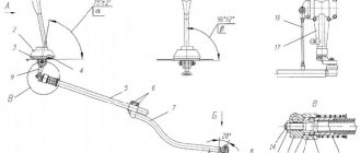
“MAZ car series 5336, 6303 and others.
Maintenance and repair manual" The file has been uploaded to the cloud service and is ready for downloading
Download speed up to 72 Mbit/s Torrent version No registration No metadata No Demo version No SMS confirmation
Cars: MAZ-533602, -533603, -533605, -533608, -533702, -54322, -543203, -543205, -543302, -544003, -54329, -54330, -555100, -555102, -551603, -551605 , -630303, -630305, -631705, -642205, -64227, -642290, -642505, -6430, -651705.
The 11.0 and 15.0 liter diesel engines used are examined in detail.
The components and assemblies of MAZ are described, a detailed description of the maintenance and repair of vehicles on the basis of ready-made spare parts is given, instructions are given for disassembling and assembling, adjusting and repairing vehicle components.
There are lists of possible faults and recommendations for their diagnosis and elimination.
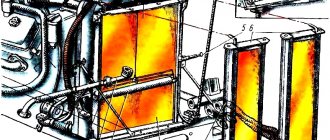
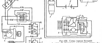
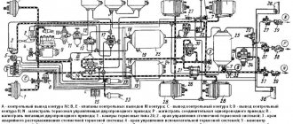
Separate sections of the manual include operating instructions for the MAZ vehicle and color diagrams of electrical equipment.
The manual is intended for engineering and technical workers of auto centers and repairmen from service stations, drivers and owners of MAZ vehicles.
Year: 2001 Language: Russian Format: DJVU Pages: 219 Size: 149 MB
Download repair instructions for MAZ vehicles:
History of creation
The history of the MAZ-6303 model began back in 1965. It was then that Belarusian designers began to take the first steps towards creating full-fledged three-axle trucks with increased payload capacity. The need to create such cars was determined by the rapidly increasing volumes of cargo transportation, as well as the poor quality and insufficient ramifications of roads of that time.
The engineers implemented their first developments in the segment of three-axle heavy-duty trucks in the MAZ-516 onboard truck with a suspended rear axle, the MAZ-520 and 515 truck tractors, as well as in the MAZ-514 onboard mainline tractor with a middle axle.
As tests showed, these experimental models were still very far from perfect, despite their promise. In particular, an increase in the carrying capacity of vehicles required the use of more powerful engines, improvements to the rear suspension, rearrangement of the chassis, etc.
Over the following years, these models underwent many changes, but the fate of each of them was different. For example, the first batch of improved MAZ-516s rolled off the assembly line in 1969. From 1970 to 1981, production of the modernized MAZ-516A and 516B continued. MAZ-515 and 520 never entered mass production, but the steering concept of the latter was later used by designers when creating the MZKT-6515. The MAZ-514 was tested in 1969, but the power of the six-cylinder YaMZ-236 engine for the model that was supposed to work as part of a road train was not enough, so the first industrial batch with a 270-horsepower YaMZ-238E engine was released only in 1974.
Over the next 10 years, MAZ designers worked fruitfully to create powerful and multifunctional trucks, and by the beginning of the 90s, the company already had in stock several quite successful models of the new generation of heavy-duty vehicles. It was this fact that helped the automobile plant not only to more or less calmly endure the economic crisis caused by the collapse of the USSR, but also to continue the development and production of new cars, which were so needed at that time to maintain the competitiveness of MAZ.
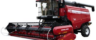
Onboard MAZ-630305
One of these bright and fresh models was the powerful onboard three-axle MAZ-6303, which stood out for its original technical solution in the form of a 6x4 wheel arrangement. This car was originally created to meet European requirements, so it was, as they say, doomed to success. The new product turned out to be so successful that almost all subsequent three-axle heavy-duty trucks of the Minsk Automobile Plant had a certain “family connection” with the MAZ-6303.
On the basis of this model, such special vehicles as the MAZ-630168 (6x2), MAZ-6317 (6x6), the powerful MAZ-630326 timber carrier, a large tractor for working as part of a road train with a carrying capacity of up to 67 thousand kg and other versions were created.
Downloading a file
“MAZ car series 5336, 6303 and others. Maintenance and repair manual"
The file has been uploaded to the cloud service and is ready for download.
We will be grateful if, after downloading this autofile, you leave your comment and give us a rating.